EP0745316B1 - Lawn mower - Google Patents
Lawn mower Download PDFInfo
- Publication number
- EP0745316B1 EP0745316B1 EP96108021A EP96108021A EP0745316B1 EP 0745316 B1 EP0745316 B1 EP 0745316B1 EP 96108021 A EP96108021 A EP 96108021A EP 96108021 A EP96108021 A EP 96108021A EP 0745316 B1 EP0745316 B1 EP 0745316B1
- Authority
- EP
- European Patent Office
- Prior art keywords
- outlet
- outlets
- gate member
- coupled
- further characterized
- Prior art date
- Legal status (The legal status is an assumption and is not a legal conclusion. Google has not performed a legal analysis and makes no representation as to the accuracy of the status listed.)
- Expired - Lifetime
Links
- 244000025254 Cannabis sativa Species 0.000 claims description 8
- 230000002093 peripheral effect Effects 0.000 description 3
- 238000006243 chemical reaction Methods 0.000 description 2
- 238000007599 discharging Methods 0.000 description 2
- 230000005540 biological transmission Effects 0.000 description 1
- 230000000903 blocking effect Effects 0.000 description 1
- 238000002485 combustion reaction Methods 0.000 description 1
- 230000000295 complement effect Effects 0.000 description 1
- 238000004904 shortening Methods 0.000 description 1
Images


Classifications
-
- A—HUMAN NECESSITIES
- A01—AGRICULTURE; FORESTRY; ANIMAL HUSBANDRY; HUNTING; TRAPPING; FISHING
- A01D—HARVESTING; MOWING
- A01D34/00—Mowers; Mowing apparatus of harvesters
- A01D34/01—Mowers; Mowing apparatus of harvesters characterised by features relating to the type of cutting apparatus
- A01D34/412—Mowers; Mowing apparatus of harvesters characterised by features relating to the type of cutting apparatus having rotating cutters
- A01D34/63—Mowers; Mowing apparatus of harvesters characterised by features relating to the type of cutting apparatus having rotating cutters having cutters rotating about a vertical axis
- A01D34/71—Mowers; Mowing apparatus of harvesters characterised by features relating to the type of cutting apparatus having rotating cutters having cutters rotating about a vertical axis with means for discharging mown material
-
- A—HUMAN NECESSITIES
- A01—AGRICULTURE; FORESTRY; ANIMAL HUSBANDRY; HUNTING; TRAPPING; FISHING
- A01D—HARVESTING; MOWING
- A01D43/00—Mowers combined with apparatus performing additional operations while mowing
- A01D43/06—Mowers combined with apparatus performing additional operations while mowing with means for collecting, gathering or loading mown material
- A01D43/077—Mowers combined with apparatus performing additional operations while mowing with means for collecting, gathering or loading mown material with auxiliary means, e.g. fans, for transporting the mown crop
-
- A—HUMAN NECESSITIES
- A01—AGRICULTURE; FORESTRY; ANIMAL HUSBANDRY; HUNTING; TRAPPING; FISHING
- A01D—HARVESTING; MOWING
- A01D2101/00—Lawn-mowers
-
- A—HUMAN NECESSITIES
- A01—AGRICULTURE; FORESTRY; ANIMAL HUSBANDRY; HUNTING; TRAPPING; FISHING
- A01D—HARVESTING; MOWING
- A01D34/00—Mowers; Mowing apparatus of harvesters
- A01D34/01—Mowers; Mowing apparatus of harvesters characterised by features relating to the type of cutting apparatus
- A01D34/412—Mowers; Mowing apparatus of harvesters characterised by features relating to the type of cutting apparatus having rotating cutters
- A01D34/63—Mowers; Mowing apparatus of harvesters characterised by features relating to the type of cutting apparatus having rotating cutters having cutters rotating about a vertical axis
Definitions
- the present invention relates to a lawn mower of the type as defined in the preamble of claim 1.
- a lawn mower of this type is described in US-A-5,107,506.
- the lawn mower has a pair of discharge chutes directed toward the opposite sides of the mower.
- a gate is moveable between first and second positions for directing the clippings through one of the discharge chutes and for blocking the flow of clippings through the other chute. This allows the clippings to be discharged toward one side of the area being mowed, as the mower is moved back and forth across the area.
- this patent does not disclose or suggest the idea of providing a mower with a discharge chute and grass collector and a gate for directing the clippings either to the discharge chute or into the grass collector without the time consuming requirement of adding or removing of components.
- Self-propelled riding lawn mowers are also often provided with a hopper for collecting clippings and a conduit system for conveying the clippings from the cutter assembly to the hopper.
- the hopper on such mowers is commonly mounted on a collection deck or hood which includes conduits for communicating the hopper with the cutter assembly.
- It is an object of the invention is to provide a new and improved lawn mower.
- Another object of the invention is to provide a new and improved lawn mower, which is capable of both collecting or discharging clippings.
- a further object of the invention is to provide a lawn mower which may be rapidly converted from collection to discharge.
- Yet another object of the invention is to provide a lawn mower which can be changed from collection to discharge without equipment changeover.
- the invention comprises a lawn mower having a cutter assembly, an engine coupled to the cutter assembly for driving the same, a discharge assembly coupled to the cutter assembly and having first and second outlets, a grass clippings collector coupled to the first outlet for collecting clippings, a discharge chute coupled to the second outlet for discharging clippings, and means mounted on the discharge assembly and movable between a first position for covering the first outlet whereby the discharge chute is coupled to the cutter assembly and the second position for covering the second outlet whereby the clippings are directly conducted to the grass clippings collector.
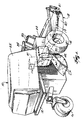
- FIG. 1 shows a mower 10 which incorporates a clipping discharge or collection system according to the invention.
- the mower 10 is otherwise conventional and accordingly, wilt be described only in general terms.
- the mower 10 includes a frame 12 which is supported at its front by a pair of drive wheels 14 at its rear by caster wheels 16.
- a cutter assembly 18 is mounted on the frame forwardly of the drive wheels 14 and includes at least one cutter blade 19 and a housing 20 supported at its front end by casters 21.
- a deck or hood 22 is mounted on the frame 12 and encloses an internal combustion engine and transmission (not shown) which power the drive wheels 14 and the cutter blade 19 in a conventional manner.
- An operator seat 24 is mounted on the deck 22 and behind the operator seat there is a grass clippings collector formed as a hopper 25 for collecting clippings from the cutter assembly 18 as will be discussed more fully below.
- the drive wheels 14 may be driven from the engine (not shown) in any conventional manner, such as by a hydraulic system which independently drives each wheel 14. Steering may be accomplished by varying the rotational speed of each drive wheel 14 through the operation of levers 26 in a manner well known in the art.
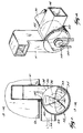
- FIGS 2-4 schematically illustrate the clipping collection system according to the invention to include a conduit 30 which connects the cutter assembly 18 to a blower assembly 32 mounted below the hopper 25.
- the blower assembly 32 includes a fan 33 disposed within a fan housing 34 having an inlet 36 which communicates with the conduit 30 and a pair of outlets 38 and 40.
- Outlet 38 communicates with one end of the first duct 41 whose other end opens into the hopper 25 and the second outlet 40 is connected to one end of a discharged duct 42.
- Housing 34 includes an arcuate outer wall 44 and a pair of circular side walls 46 and 48.
- the inlet 36 comprises a central opening in the side wall 46.
- the outlets 38 and 40 comprise peripheral openings in the outer wall 44 which are respectively connected to ducts 41 and 42.
- one wall of each conduit is tangent with the outer wall 44.
- the fan 33 includes a shaft 50 rotatably supported by a bearing 52 mounted on the side wall 48, and may be driven in any suitable manner such as by means of a pulley 53 mounted on shaft 50 and suitably coupled to the engine (not shown) by a belt 54.
- a gate 55 is mounted to selectively close one of the outlets 38 or 40 while the other remains open.
- the gate 55 is shown in Figure 5 and includes a circular plate 58 having a coaxial annular pivot sleeve 60.
- a shell 62 is fixed to the periphery of plate 58 and extends for about 270° or three quadrants.
- the pivot sleeve 60 is received on a complementary pivot bushing 64 extending coaxially inwardly from the side wall 48.
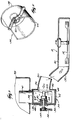
- the gate 55 is pivoted between its alternate positions by a linkage 66 mounted on the side of housing 34.
- the linkage 66 includes a hand lever 68 which is pivotally mounted about a fixed pivot axis by a pin 70 extending outwardly from housing 34.
- Lever 68 includes a first arm 72 positioned to be gripped by the operator and a second arm 74 which extends obliquely relative to the first arm 72.
- a link 76 is pivotally coupled by a pin 78 to the free end of the second arm 74.
- the opposite end of link 76 is pivotally coupled to a pin 80 which extends laterally from the plate 58 and through an arcuate slot 82 formed in the housing wall 48. Slot 82 subtends an arc of about 90° around the axis of the pivot bushing 64.
- a helical spring 84 extends from pin 78 to an anchor 86 on the housing 34 generally below the hand lever 68.
- Figure 6 shows the linkage 66 in a position where the gate covers the opening 38, the opening 40 being uncovered.
- the spring 84 acting on pin 78 urges the pin downwardly thereby tending to hold the link 76 and hence the gate 55 in this position.
- Pivotal movement of the hand lever 68 in a clockwise direction moves the pin 78 in a clockwise arc about the axis of pin 70 and against the biasing force of spring 84.
- the link 76 moves toward the right as viewed in Figure 6 which thereby moving the pin 80 clockwise in slot 82 which pivots the gate 55 about pivot bushing 64.
- a mechanical latching device may be provided for holding the gate 55 in each of its positions in addition to the biasing force of the spring 84.
- Rotation of the fan 33 creates a suction drawing clippings from the cutter assembly 18 through duct 30 to the inlet 36 of blower assembly 32. If it is desired to collect the clippings, the gate 55 is placed in the position shown in Figure 2. This closes the outlet 40 and opens the outlet 38. On the other hand, if it is desired to discharge the clippings gate 55 is moved from its position shown in Figure 2 to its alternate position. This opens outlet 40 and closes outlet 38 so that the clippings are directed to discharge as through conduit 42. It can be seen that the mower according to the invention can be converted from discharge to collection relatively rapidly without the need for tools, a separate deck or a time consuming conversion operation.
- FIG. 8 shows an alternate embodiment of the invention in which parts corresponding to those in FIGURES 1-7 are given the same reference numeral, except the gate and the components thereof which are distinguished by a prime (').
- the peripheral extent of the gate member 55' is approximately equal to that required to close the outlets 38 and 40.
- the gate 55' is positioned on an extension 90 of the peripheral rim of plate so that it will engage the end of duct 42 to limit rotation in a counter-clockwise direction and a stop 92 formed on the lower end of duct 41 to limit rotation in the clockwise direction. Shortening the gate 55' in this manner eliminates the possibility that clippings can collect between the gate and the housing 34.
- the linkage 66' is shown in Figure 9.
- the pin 70' is mounted on plate 58' and extends outwardly through an arcuate slot 82' in the side wall 48'.
- the linkage 66' is similar to the linkage 66 shown in Figures 6 and 7 except that there is an additional link 98 slidably received in a collar 100 pivotally mounted on link 74'.
- One end of link 98 is pivotally coupled to link 76' and intermediate its ends. The link 98 can be pushed or pulled during movement of the gate 55' to assist movement of the linkage 66' off of its top dead center position.
Landscapes
- Life Sciences & Earth Sciences (AREA)
- Environmental Sciences (AREA)
- Harvester Elements (AREA)
Description
Claims (9)
- A lawn mower (10) including a cutter assembly (18), an engine for driving the cutter assembly, a discharge assembly (32) coupled to the cutter assembly, the discharge assembly including first and second outlets (38,40), gate means (55,55') mounted on the discharge assembly and moveable between a first position for closing the first outlet and opening the second outlet and a second position for opening the first outlet and closing the second outlet,
characterised in that
a grass clippings collector (25) is coupled to the first outlet (38) and a discharge chute (42) is coupled to the second outlet (40) whereby clippings are permitted to flow to the discharge chute and are prevented from flowing to the clipping collector when the gate means is in its first position and clippings are permitted to flow to the clipping collector and are prevented from flowing to the discharge chute when the gate means is in its second position. - The lawn mower set forth in claim 1 wherein said discharge assembly includes a blower (32), said blower having an inlet (30) connected to the cutter assembly further characterized in that the blower includes a pair of outlets (38, 40) coupled respectively to the clippings collector (25) and the discharge chute (42), the means (55, 55') for closing the first or second outlets comprising a gate member movable between a first position closing said first outlet and a second position closing the second outlet.
- The mower set forth in claim 2 wherein said blower includes a fan (33) and an annular housing (34) surrounding said fan and having a pair of circular side walls (46, 48) and an annular outer wall (44), said inlet (36) comprising an opening in one of said side walls, further characterized in that said first and second openings (38, 40) comprising spaced openings in said outer wall, said gate member (55, 55') comprising an arcuate member sized to cover each of said outlets individually and pivotably movable between said first an second positions.
- The mower set forth in claims 2 or 3 further characterized in that each of said outlets (38, 40) is substantially equal in size, said gate member (55') being arcuate in a plane generally normal to the axis of said annular housing and having a size about equal to that of said outlets.
- The mower bet forth in any of claims 1-4 and further characterized in that linkage means (66) external of said blower is provided for moving said gate member (55, 55') between its first and second positions.
- The mower set forth in any of claims 3-5 further characterized in that the blower assembly (32) includes a cylindrical housing (44) portion having an axis, said outlets (38, 40) lying in an arc concentric with said axis, the gate member (55, 55') including mounting means (58, 58') coupled to the gate member and pivotally mounted on the housing for moving the gate member in an arcuate path adjacent the arc formed by the outlets.
- The lawn mower set forth in claims 5 or 6 further characterized in that the linkage means (66, 66') includes a hand lever (68, 68') pivotally mounted on the housing, an operating link (76, 76') pivotally coupled at one end to the hand lever and at its other end to the gate member (55, 55'), said linkage means having first and second positions, pivotal movement of the hand lever being operative to move said linkage means between its first and second positions, said linkage means being coupled to said gate member and operative to move the gate member between its first and second positions as said linkage means moves between its first and second positions.
- The mower set forth in any of claims 5-7 further characterized in that biasing means is provided for biasing said linkage means into each of its first and second positions.
- The mower set forth in any of claims 5-8 further characterized in that said linkage means (66') includes a second link (98) pivotally coupled to the operating link intermediate its end, and slidably mounted on the hand lever to permit the linkage means to be pulled or pushed through a dead center position.
Applications Claiming Priority (4)
| Application Number | Priority Date | Filing Date | Title |
|---|---|---|---|
| US45844095A | 1995-06-02 | 1995-06-02 | |
| US458440 | 1995-06-02 | ||
| US08/610,585 US5826416A (en) | 1995-06-02 | 1996-03-07 | Lawn mower having a dual discharge system |
| US610585 | 1996-03-07 |
Publications (2)
| Publication Number | Publication Date |
|---|---|
| EP0745316A1 EP0745316A1 (en) | 1996-12-04 |
| EP0745316B1 true EP0745316B1 (en) | 1999-01-13 |
Family
ID=27039008
Family Applications (1)
| Application Number | Title | Priority Date | Filing Date |
|---|---|---|---|
| EP96108021A Expired - Lifetime EP0745316B1 (en) | 1995-06-02 | 1996-05-20 | Lawn mower |
Country Status (3)
| Country | Link |
|---|---|
| US (1) | US5826416A (en) |
| EP (1) | EP0745316B1 (en) |
| DE (1) | DE69601325T2 (en) |
Families Citing this family (28)
| Publication number | Priority date | Publication date | Assignee | Title |
|---|---|---|---|---|
| FR2763784B1 (en) * | 1997-05-28 | 2000-03-17 | Etesia | LAWN MOWER WITH DOOR CONDUCTOR INCLUDING IN PARTICULAR A COLLECTOR FOR CUT GRASS |
| US6073305A (en) * | 1998-03-02 | 2000-06-13 | Hesskamp; Scott | Debris blower |
| US6192666B1 (en) | 1999-03-10 | 2001-02-27 | Scag Power Equipment, Inc. | Lawn mower |
| US6370855B1 (en) * | 2000-08-21 | 2002-04-16 | Magic Circle Corporation | Grass blower for lawn mower |
| US6449933B1 (en) | 2000-09-29 | 2002-09-17 | Kuboto Corporation | Lawn mower |
| US6681443B1 (en) | 2001-10-19 | 2004-01-27 | Michel J. Bourgeois | Blower |
| DE20204896U1 (en) | 2002-01-30 | 2002-08-14 | Cramer GmbH & Co. KG, 26789 Leer | Ride-on mower |
| US6910324B2 (en) | 2002-02-01 | 2005-06-28 | The Toro Company | Multi-bladed rotary cutting deck with mulching and discharge/collection modes |
| US20040128970A1 (en) * | 2003-01-03 | 2004-07-08 | Gazlay Richard E. | Direction changing feature for lawnmower discharge |
| US7069712B2 (en) * | 2004-06-21 | 2006-07-04 | Deere & Company | Mower deck with blower |
| US7062898B2 (en) * | 2004-06-22 | 2006-06-20 | Wec Company | Mower attachment mechanism |
| US20060272309A1 (en) * | 2005-06-03 | 2006-12-07 | Electrolux Professional Outdoor Products, Inc. | Collection system |
| US7240474B2 (en) | 2005-10-13 | 2007-07-10 | Deere & Company | Power assist rear discharge mower deck |
| US20070101692A1 (en) * | 2005-11-09 | 2007-05-10 | Barlow Dale V | Lawn mower |
| US7841044B1 (en) * | 2006-09-26 | 2010-11-30 | Rick A. Weihl | Dual-deflector riding blower |
| CA2585274C (en) * | 2007-04-10 | 2011-07-19 | Stanley J. Boyko | Rotary mower over-center self-locking wing lift |
| US7849665B2 (en) * | 2009-03-23 | 2010-12-14 | Honda Motor Co., Ltd. | Recirculating grass bagging apparatuses and methods |
| JP5576104B2 (en) * | 2009-12-07 | 2014-08-20 | 株式会社クボタ | Riding mower |
| US8171709B1 (en) | 2010-10-27 | 2012-05-08 | Schiller Grounds Care, Inc. | Mower baffle system |
| FR2980666B1 (en) | 2011-09-29 | 2014-08-22 | Const Metalliques De L Ouest Secmo Soc Et | DRIVE ASSEMBLY FOR A MACHINE COMPRISING A CUTTING TRAY AND A STORAGE BASKET |
| USD685822S1 (en) | 2013-01-04 | 2013-07-09 | Mtd Products Inc | Blower attachment for a walk-behind lawn mower |
| US10045481B2 (en) | 2014-11-05 | 2018-08-14 | Rick Chase | Lawnmower discharge device |
| US11234365B2 (en) | 2017-10-31 | 2022-02-01 | Clark Equipment Company | Baffles for mower deck |
| US11957079B2 (en) | 2018-10-17 | 2024-04-16 | Metalcraft Of Mayville, Inc. | Stand-on blower |
| US11503762B2 (en) | 2018-11-29 | 2022-11-22 | Honda Motor Co., Ltd. | Shutter assembly for a lawnmower, lawnmower having same, and convertible lawnmower |
| US10945366B2 (en) * | 2019-03-12 | 2021-03-16 | Honda Motor Co., Ltd. | Cutter housing assembly for a lawnmower, lawnmower having same, and convertible lawnmower |
| US11044846B2 (en) * | 2019-04-01 | 2021-06-29 | Honda Motor Co., Ltd. | Cutter housing assembly for a lawnmower, lawnmower having same, and convertible lawnmower |
| US11122738B2 (en) * | 2019-04-23 | 2021-09-21 | Honda Motor Co., Ltd. | Cutter housing assembly for a lawnmower, lawnmower having same, and convertible lawnmower |
Family Cites Families (25)
| Publication number | Priority date | Publication date | Assignee | Title |
|---|---|---|---|---|
| US2947571A (en) * | 1954-09-30 | 1960-08-02 | Int Harvester Co | Dump-body assembly and attaching means for complementary tractor |
| US2926477A (en) * | 1958-11-17 | 1960-03-01 | Harvey H Bebow | Self-propelled forage harvester with common conveying means for loading and unloading thereof |
| US3357749A (en) * | 1966-05-25 | 1967-12-12 | Sperry Rand Corp | Silage distributor |
| DE1930318A1 (en) * | 1969-06-14 | 1970-12-17 | Ernst Weichel | Device for evenly distributing the conveyed material emerging from the blower pipes |
| CH517865A (en) * | 1970-06-20 | 1972-01-15 | Schmidt Alfred Ing Fa | Attachment for work vehicle for picking up mown grass, leaves or the like from road verges |
| US3702051A (en) * | 1970-09-08 | 1972-11-07 | John Deines | Independently operable dual drive wheel riding power mower |
| US3862539A (en) * | 1973-07-27 | 1975-01-28 | J L Stevens | Ground clearing attachment for tractors |
| US3986463A (en) * | 1973-08-07 | 1976-10-19 | Agrecology, Inc. | Agricultural implement |
| US3863428A (en) * | 1973-11-14 | 1975-02-04 | Robert L Baxter | Blockage monitor for a cotton picking machine |
| US4047365A (en) * | 1975-08-25 | 1977-09-13 | Suggs Charles W | Automatic leaf spreader for a tobacco harvester |
| US4078365A (en) * | 1976-09-13 | 1978-03-14 | Gould Paper Corporation | Tree nut windrowing blower with automatic oscillating blower discharge |
| US4156337A (en) * | 1978-03-13 | 1979-05-29 | Allis-Chalmers Corporation | Pivotally mounted grass catcher for riding mower |
| JPS54146747A (en) * | 1978-04-28 | 1979-11-16 | Fuso Light Alloys Co Ltd | Treating method and device of cut lawn |
| US4226074A (en) * | 1979-01-08 | 1980-10-07 | Excel Industries, Inc. | Lawnmower deck |
| CA1090588A (en) * | 1979-04-23 | 1980-12-02 | Balthes Farm Equipment Manufacturing Limited | Leaf distributor for mechanical harvester |
| CA1110854A (en) * | 1979-05-16 | 1981-10-20 | Earl H. Kidd | Grass discharge assembly for chuteless mower housing |
| US4258539A (en) * | 1979-08-29 | 1981-03-31 | Outboard Marine Corporation | Grass discharge chute deflector for rotary lawn mower |
| US4835951A (en) * | 1984-05-03 | 1989-06-06 | Walker Manufacturing Company | Mower apparatus |
| US4635047A (en) * | 1984-08-27 | 1987-01-06 | Deere & Company | Air system monitor for a cotton harvester |
| US4660359A (en) * | 1984-10-23 | 1987-04-28 | Deere & Company | Air system for a cotton harvester |
| US4881362A (en) * | 1985-02-06 | 1989-11-21 | Parker Sweeper Company | Mobile vacuum system for use with a riding tractor mower |
| CA2026682A1 (en) * | 1989-10-10 | 1991-04-11 | Alfred Eggenmueller | Method and apparatus for mulching of grass, leafage, or similar material |
| US5033260A (en) * | 1989-11-06 | 1991-07-23 | Jerry Frederick L | Lawn mower deflector |
| US5107566A (en) * | 1991-06-26 | 1992-04-28 | Schmid Roy J | Directed discharge blower chute and method |
| US5189868A (en) * | 1992-03-23 | 1993-03-02 | Jerry Hill | Leaf mulcher |
-
1996
- 1996-03-07 US US08/610,585 patent/US5826416A/en not_active Expired - Fee Related
- 1996-05-20 DE DE69601325T patent/DE69601325T2/en not_active Expired - Fee Related
- 1996-05-20 EP EP96108021A patent/EP0745316B1/en not_active Expired - Lifetime
Also Published As
| Publication number | Publication date |
|---|---|
| DE69601325D1 (en) | 1999-02-25 |
| EP0745316A1 (en) | 1996-12-04 |
| DE69601325T2 (en) | 1999-05-27 |
| US5826416A (en) | 1998-10-27 |
Similar Documents
| Publication | Publication Date | Title |
|---|---|---|
| US5826416A (en) | Lawn mower having a dual discharge system | |
| US5438770A (en) | Snowblower | |
| US6192666B1 (en) | Lawn mower | |
| US6874310B2 (en) | Variable mulching system for a lawnmower | |
| EP1348327B1 (en) | Lawn mower | |
| EP0300383B1 (en) | Walk-behind lawn mower | |
| US4589249A (en) | Mowing apparatus | |
| US6000642A (en) | Wood chipper with infeed chute safety device | |
| EP1785027B1 (en) | Lawn mower | |
| EP3583837B1 (en) | Lawn mower | |
| US20040168424A1 (en) | Deck assembly for a self-propelled, walk-behind rotary lawn mower | |
| US10897845B2 (en) | Cutter housing assembly for a lawnmower, lawnmower having same, and convertible lawnmower | |
| WO1998058530A1 (en) | Lawn mower | |
| CA2228066C (en) | Mower deck lid locking mechanism | |
| US6966169B2 (en) | Mowing machine chute cleaner apparatuses and methods | |
| US3817547A (en) | Lawn mower handle mounting | |
| US3795095A (en) | Vented rotary lawn mower | |
| US4716717A (en) | Power lawn mower | |
| EP0634090B1 (en) | Improvements in and relating to rotary mowers | |
| EP0738462B1 (en) | Lawn mowers having a pivoting grass chute | |
| JPH012508A (en) | Mower cutter blade attachment device | |
| JP4389045B2 (en) | Lawn mower | |
| JP3207975B2 (en) | Mower transport section structure | |
| JP3649475B2 (en) | Double rotary mower | |
| JPH0450182Y2 (en) |
Legal Events
| Date | Code | Title | Description |
|---|---|---|---|
| PUAI | Public reference made under article 153(3) epc to a published international application that has entered the european phase |
Free format text: ORIGINAL CODE: 0009012 |
|
| AK | Designated contracting states |
Kind code of ref document: A1 Designated state(s): DE FR GB |
|
| 17P | Request for examination filed |
Effective date: 19970509 |
|
| 17Q | First examination report despatched |
Effective date: 19970620 |
|
| GRAG | Despatch of communication of intention to grant |
Free format text: ORIGINAL CODE: EPIDOS AGRA |
|
| GRAG | Despatch of communication of intention to grant |
Free format text: ORIGINAL CODE: EPIDOS AGRA |
|
| GRAG | Despatch of communication of intention to grant |
Free format text: ORIGINAL CODE: EPIDOS AGRA |
|
| GRAH | Despatch of communication of intention to grant a patent |
Free format text: ORIGINAL CODE: EPIDOS IGRA |
|
| GRAH | Despatch of communication of intention to grant a patent |
Free format text: ORIGINAL CODE: EPIDOS IGRA |
|
| GRAA | (expected) grant |
Free format text: ORIGINAL CODE: 0009210 |
|
| AK | Designated contracting states |
Kind code of ref document: B1 Designated state(s): DE FR GB |
|
| REF | Corresponds to: |
Ref document number: 69601325 Country of ref document: DE Date of ref document: 19990225 |
|
| ET | Fr: translation filed | ||
| PGFP | Annual fee paid to national office [announced via postgrant information from national office to epo] |
Ref country code: FR Payment date: 19990518 Year of fee payment: 4 |
|
| PGFP | Annual fee paid to national office [announced via postgrant information from national office to epo] |
Ref country code: DE Payment date: 19990629 Year of fee payment: 4 |
|
| PLBE | No opposition filed within time limit |
Free format text: ORIGINAL CODE: 0009261 |
|
| STAA | Information on the status of an ep patent application or granted ep patent |
Free format text: STATUS: NO OPPOSITION FILED WITHIN TIME LIMIT |
|
| 26N | No opposition filed | ||
| PG25 | Lapsed in a contracting state [announced via postgrant information from national office to epo] |
Ref country code: GB Free format text: LAPSE BECAUSE OF NON-PAYMENT OF DUE FEES Effective date: 20000520 |
|
| GBPC | Gb: european patent ceased through non-payment of renewal fee |
Effective date: 20000520 |
|
| PG25 | Lapsed in a contracting state [announced via postgrant information from national office to epo] |
Ref country code: FR Free format text: LAPSE BECAUSE OF NON-PAYMENT OF DUE FEES Effective date: 20010131 |
|
| PG25 | Lapsed in a contracting state [announced via postgrant information from national office to epo] |
Ref country code: DE Free format text: LAPSE BECAUSE OF NON-PAYMENT OF DUE FEES Effective date: 20010301 |
|
| REG | Reference to a national code |
Ref country code: FR Ref legal event code: ST |