EP0744733A2 - Electronic musical instrument - Google Patents
Electronic musical instrument Download PDFInfo
- Publication number
- EP0744733A2 EP0744733A2 EP96108169A EP96108169A EP0744733A2 EP 0744733 A2 EP0744733 A2 EP 0744733A2 EP 96108169 A EP96108169 A EP 96108169A EP 96108169 A EP96108169 A EP 96108169A EP 0744733 A2 EP0744733 A2 EP 0744733A2
- Authority
- EP
- European Patent Office
- Prior art keywords
- musical
- musical tone
- tone
- synthesizing device
- tones
- Prior art date
- Legal status (The legal status is an assumption and is not a legal conclusion. Google has not performed a legal analysis and makes no representation as to the accuracy of the status listed.)
- Granted
Links
Images


Classifications
-
- G—PHYSICS
- G10—MUSICAL INSTRUMENTS; ACOUSTICS
- G10H—ELECTROPHONIC MUSICAL INSTRUMENTS; INSTRUMENTS IN WHICH THE TONES ARE GENERATED BY ELECTROMECHANICAL MEANS OR ELECTRONIC GENERATORS, OR IN WHICH THE TONES ARE SYNTHESISED FROM A DATA STORE
- G10H1/00—Details of electrophonic musical instruments
- G10H1/0033—Recording/reproducing or transmission of music for electrophonic musical instruments
-
- G—PHYSICS
- G10—MUSICAL INSTRUMENTS; ACOUSTICS
- G10H—ELECTROPHONIC MUSICAL INSTRUMENTS; INSTRUMENTS IN WHICH THE TONES ARE GENERATED BY ELECTROMECHANICAL MEANS OR ELECTRONIC GENERATORS, OR IN WHICH THE TONES ARE SYNTHESISED FROM A DATA STORE
- G10H7/00—Instruments in which the tones are synthesised from a data store, e.g. computer organs
- G10H7/002—Instruments in which the tones are synthesised from a data store, e.g. computer organs using a common processing for different operations or calculations, and a set of microinstructions (programme) to control the sequence thereof
- G10H7/004—Instruments in which the tones are synthesised from a data store, e.g. computer organs using a common processing for different operations or calculations, and a set of microinstructions (programme) to control the sequence thereof with one or more auxiliary processor in addition to the main processing unit
Definitions
- This invention relates to a music system and an electronic musical instrument which reproduce automatic performance data such as MIDI (Musical Instrument Digital Interface) data.
- MIDI Musical Instrument Digital Interface
- a computer music system which is sometimes generically called an electronic musical instrument, which reads out automatic performance data such as MIDI data stored in a floppy disk or a hard disk, and synthesizes musical tones according to the automatic performance data, by the use of an FM (frequency modulation) tone generator or a WT (wave table) tone generator, to thereby produce musical sounds.
- automatic performance data such as MIDI data stored in a floppy disk or a hard disk
- FM (frequency modulation) tone generator or a WT (wave table) tone generator to thereby produce musical sounds.
- Fig. 1 shows the arrangement of an example of the conventional computer music system.
- the computer music system is comprised of an ordinary host computer 1 as a main system, and a sound board 10 as a subsystem connected to the main system via a predetermined interface.
- the host computer 1 has a construction similar to that of an ordinary personal computer, i.e. it is comprised of a CPU 2, a program memory 3, a ROM and a RAM 4, a keyboard and a mouse 5, a CRT 6, a hard disk 7, a floppy disk 8, and an MIDI interface 9.
- the CPU 2 reads out performance data such as MIDI data from the hard disk 7 or the floppy disk 8, which are provided as external memory devices, and transmits the performance data to the sound board 10 according to a program (program for automatic performance processing) stored in the program memory 3.
- the ROM and RAM 4 store a program for starting the host computer 1, and various kinds of data used and/or obtained during execution of programs by the CPU 2. Further, the host computer 1 can carry out preparation and edition of performance data by using the keyboard and mouse 5 and the CRT 6.
- the MIDI interface 9 takes in MIDI data from an external device, and sends out MIDI data to an external device.
- the sound board 10 is comprised of a CPU 11, a program memory 12, a communication interface 13, a tone generator LSI 14, and a D/A converter 15.
- the CPU 11 receives MIDI data from the host computer 1 via the communication interface 13, generates musical tone data, based on the MIDI data by the use of the tone generator LSI 14, and converts the musical tone data to analog signals, to thereby generate musical tones by a loudspeaker, not shown, according to a program (program for automatic performance processing) stored in the program memory 12.
- Fig. 2 shows the arrangement of another example of the conventional computer music system.
- the computer music system of Fig. 2 is comprised of an ordinary personal computer 20, and distinguished from the example of Fig. 1 in that the personal computer 20 includes a wave table 21 which stores waveform data indicative of waveforms of musical tones, and a D/A converter 15.
- the system of Fig. 2 synthesizes and generates musical tones by itself.
- the CPU 2 reads out performance data such as MIDI data from a hard disk 7 or a floppy disk 8, as external memory devices, then reads out waveform data from the wave table 21, based on the performance data, and converts the waveform data to analog signals, to thereby generate musical tones by a loudspeaker, not shown, according to a musical tone-synthesizing program stored in the program memory 3.
- the CPU 2 is capable of carrying out parallel processing, i.e. it can carry out other processings as well as synthesizing and generating musical tones.
- Fig. 3 shows a program for synthesizing musical tones, which is executed by the above described computer music system of Fig. 2.
- performance data such as MIDI data are read out from the hard disk 7 or the floppy disk 8 and interpreted by the CPU 2.
- a key code of the MIDI data is assigned to a tone-generating channel for generating a musical tone.
- a tone-generating channel for generating a musical tone.
- the program proceeds to a step S4, wherein an envelope of the musical tone is formed based on velocity data (velocity of key depression or key release) of the MIDI data.
- a step S5 an address in the wave table 21 is determined, which determines which waveform data should be read out, based on the key code of the MIDI data.
- the wave table 21 is accessed based on the above determined address, to read out corresponding waveform data.
- the waveform data is multiplied by the envelope formed at the step S4 to prepare final waveform data (musical tone data), which in turn is delivered to the D/A converter 15.
- the final waveform data is then converted to an analog signal by the D/A converter 15, followed by generating a musical tone by the loudspeaker.
- the program proceeds to a step S8, wherein it is determined whether or not the automatic performance is to be terminated. If it is not to be terminated, the answer is negative (NO), and then the program returns to the step S1.
- the process of synthesizing a musical tone is expressed in a simplified (schematic) manner. However, the procedure from the step S4 to the step S7 for determining an instantaneous value of a musical tone waveform is repeatedly executed every predetermined sampling period until sounding of the musical tone is completed.
- the capacity of synthesizing musical tones is determined by the capacity of the sound board 10. For example, if performance data stored in the hard disk 7 or the floppy disk 8 or performance data such as MIDI data supplied from an external device, etc. are designed for use by a tone generator with a larger capacity than the capacity of the sound board 10, the sound board 10 cannot fully process the performance data. Further, although in recent days a CPU which has an improved processing capacity (processing speed) has been used, the CPU is used only for controlling channels and preparing and editing performance data, resulting in insufficient utilization of the improved processing capacity.
- processing speed processing speed
- the synthesization of musical tones is entirely carried out by the use of software. Therefore, if, for example, the number of tone-generating channels is increased, an increased burden is imposed on the program, which adversely affects execution of the other processings which are executed in parallel with the synthesization by the CPU 2. Further, to avoid this inconvenience, merely a simple musical tone-synthesizing algorithm can be employed, resulting in degraded quality of sounds generated, compared with the quality of sounds generated by a system employing an exclusive sound board.
- the present invention provides a music system comprising a subsystem including a first musical tone-synthesizing device that synthesizes musical tones, based on performance data externally supplied thereto, and a mixing device that mixes together the musical tones synthesized by the first musical tone-synthesizing device and external musical tones externally generated and supplied thereto, and a main system including performance data-processing device that controls performance data indicative of musical tones to be performed and transmits the performance data to the subsystem at predetermined timing, and a second musical tone-synthesizing device that synthesizes musical tones, based on the performance data, when the first musical tone-synthesizing device is in a predetermined state, wherein the main system transmits the musical tones synthesized by the second musical tone-synthesizing device to the subsystem, as the external musical tones.
- the second musical tone-synthesizing device synthesizes musical tones, based on the performance data, when the first musical tone-synthesizing device reaches a limit of processing capacity thereof.
- the first musical tone-synthesizing device synthesizes musical tones by hardware.
- the first musical tone-synthesizing device and the second musical tone-synthesizing device operate in parallel to synthesize musical tones, based on the performance data.
- the first musical tone-synthesizing device and the second musical tone-synthesizing device synthesize musical tones having respective different characteristics.
- the present invention also provides an electronic music instrument comprising a performance data-processing device that controls performance data indicative of musical tones to be performed and transmits the performance data at predetermined timing, a first musical tone-synthesizing device that synthesizes musical tones, based on the performance data, a second musical tone-synthesizing device that synthesizes musical tones, based on the performance data, when the first musical tone-synthesizing device is in a predetermined state, a mixing device that mixes together the musical tones synthesized by the first musical tone-synthesizing device and the musical tones synthesized by the second musical tone-synthesizing device, and a sounding device that generates the musical tones mixed together by the mixing device.
- the first musical tone-synthesizing device synthesizes musical tones by hardware
- the second musical tone-synthesizing device synthesizes musical tones by software
- Fig. 4 there is schematically illustrated the whole arrangement of a computer music system according to a first embodiment of the invention.
- the computer music system according to the first embodiment is comprised of a host computer 30, and a sound board 10 externally connected thereto.
- the host computer 30 is comprised of a wave table 21 which stores waveform data indicative of waveforms of musical tones, and a program memory 22 which stores programs including a musical tone-synthesizing program for synthesizing musical tone data by reading out waveform data from the wave table 21, based on automatic performance data such as MIDI data.
- a CPU 2 operates on the musical tone-synthesizing program stored in the program memory 22 to read out automatic performance data such as MIDI data from a hard disk 7 or a floppy disk 8, which are provided as external memory devices, and transmit the read-out automatic performance data (MIDI data) to the sound board 10 when an empty channel is present on the sound board 10 side.
- the CPU 2 reads out waveform data from the wave table 21 provided in the host computer 30, and transmits the read-out waveform data to the sound board 10.
- the sound board 10 which has a similar construction to that of the sound board of the conventional computer music system in Fig. 1, receives the MIDI data from the host computer 30 via a communication interface 13 and synthesizes musical tone data by means of a tone generator LSI 14, according to a program stored in a ROM and RAM 12. Then, musical tone data synthesized by the host computer 30 and musical tone data synthesized by the sound board 10 are mixed together, and the mixed musical tone data is converted to an analog signal by means of a D/A converter 15, whereby sound of a musical tone based on the mixed musical tone data is generated from a loudspeaker, not shown.
- the tone generator LSI 14 most of processings with large burden are executed by the tone generator LSI 14, and therefore the CPU 11, the ROM and RAM 12, and the communication I/F 13 may be omitted from the construction of the sound board 10, if required.
- Fig. 5 conceptually represents a manner of synthesizing musical tone data by means of software, which is employed by the computer music system according to the first embodiment.
- MIDI data read from the hard disk 7 or the floppy disk 8 is interpreted by a performance data-processing section 40, and transmitted to the tone generator LSI 14 of the sound board 10.
- waveform data is read out from the wave table 21 by software, based on the MIDI data, to synthesize musical tone data from the waveform data.
- musical tone data is synthesized by the tone generator LSI (hardware) 14, based on MIDI data from the host computer 30, and musical tone data synthesized by the host computer 10 and musical tone data synthesized by the sound board 10 are mixed together by a mixer 43 of the sound board 10, to thereby generate sound of the mixed musical tone.
- synthesization of musical tones is carried out by the sound board 10.
- the host computer 30 has three channels to which musical tone data can be assigned, while the sound board 10 has seven channels to which musical tone data can be assigned.
- step S10 in Fig. 6, in the host computer 30, performance data such as MIDI data stored in the hard disk 7 or the floppy disk 8 is read out and interpreted. Then, at a step S11, it is determined whether or not the MIDI data is key-ON data or key-OFF data. If the MIDI data is neither key-ON data nor key-OFF data, the answer is negative (NO), and then the program proceeds to a step, not shown, for executing a processing corresponding to the MIDI data, description of which is omitted.
- the program proceeds to a step S12, wherein a key code of the MIDI data is assigned to a tone-generating channel for generating a musical tone.
- a key code of the MIDI data is assigned to a tone-generating channel for generating a musical tone.
- the key code is assigned to the empty channel in the sound board 10.
- the key code is assigned to an empty channel in the host computer 30. Details of the channel assignment processing will be described hereinafter.
- a step S13 it is determined whether or not assignment of the key data to a channel in the host computer 30 has been made. If assignment of the key data to a channel in the host computer 30 has not been made, i.e. if assignment of the key data to a channel in the sound board 10 has been made, the answer is negative (NO), and then the program proceeds to a step S14.
- the MIDI data is transmitted via the communication interface 13 to the sound board 10.
- it is determined at a step S16 whether or not the automatic performance is to be terminated. If it is not to be terminated, the answer is negative (NO), and then the program returns to the step S10.
- the steps S10 to S16 are repeatedly executed. In this manner, normally MIDI data are sequentially transmitted to the sound board 10.
- step S20 it is determined at a step S20 whether or not MIDI data has been received from the host computer 30. If MIDI data has been received from the host computer 30, the answer is affirmative (YES), and then the program proceeds to a step S21.
- step S21 musical tone data is synthesized based on the MIDI data by the tone generator LSI 14. Then, at a step S22, if musical tone data synthesized by the host computer 30 has been transmitted to the sound board 10, the transmitted musical tone data and the musical tone data synthesized by the tone generator LSI 14 are mixed together.
- step S23 the mixed musical tone data is transmitted to the D/A converter 15, wherein the mixed musical tone data is converted to an analog signal, whereby musical sound is generated from the loudspeaker.
- step S15 waveform data is synthesized based on the MIDI data according to the musical tone-synthesizing program stored in the program memory 22, and the synthesized waveform data is transmitted to the sound board 10. More specifically, an envelope of the musical tone is formed based on velocity data (velocity of key depression or key release) of the MIDI data, and then an address of the wave table 21 is determined for determining which waveform data should be read out, based on the key code of the MIDI data.
- the wave table 21 is accessed based on the above determined address, to read out corresponding waveform data. Further, the read-out waveform data is multiplied by the envelope to thereby synthesize final waveform data (musical tone data), followed by transmitting the final waveform data to the sound board 10. Therefore, in this case, the musical tone data (waveform data) transmitted by the host computer 30 at the step S22 and the musical tone data (waveform data) synthesized by the sound board 10 are mixed together, whereby a musical tone based on the mixed musical tone data is generated.
- step S30 in Fig. 7 it is determined by the host computer 30 whether or not the read-out MIDI data indicates a key-ON event. If it indicates a key-ON event, the answer is affirmative (YES), and then the program proceeds to a step S31.
- step S31 it is determined whether or not an empty channel is present in the sound board 10 which is a subsystem of the computer music system. If the sound board 10 has an empty channel, the answer is affirmative (YES), and then the program proceeds to a step S32.
- the key code (KC) of the MIDI data is assigned to the empty channel in the sound board 10, and the assigned channel (ch) and the key code (KC) of the MIDI data are stored in the RAM 4 in the host computer 30. Then, the program returns to the main routine of Fig. 6, followed by executing the step S13.
- step S33 it is determined whether or not the host computer 30 has an empty channel. If the host computer 30 has no empty channel, i.e. if all the channels in the sound board 10 and the host computer 30 are occupied, the answer is negative (NO). Then, the program proceeds to a step, not shown, wherein sounding of the musical tone is inhibited, or alternatively a musical tone which is just decaying is stopped from being generated, to secure an empty channel to which the key code data is to be assigned.
- step S34 the key code is assigned to the empty channel in the host computer 30 as the tone-generating channel, and the assigned channel (ch) and the key code (KC) of the MIDI data are stored in the RAM 4 in the host computer 30. Then, the program returns to the main routine, followed by executing the step S13.
- step S30 If the MIDI data does not indicate a key-ON event, i.e. if the MIDI data indicates a key-OFF event, the answer to the question of the step S30 is negative (NO), and then the program proceeds to a step S35.
- step S35 the assignment of the key code to the tone-generating channel is canceled based on the key code (KC) and the channel (ch) stored in the RAM 4, to release the channel from the assignment. Then, the program returns to the main routine, followed by executing the step S13.
- the host computer 30 does not only have a function of controlling empty channels but also a function of synthesizing musical tones by software.
- the host computer 30 can synthesize musical tones.
- the processing capacity of the entire computer music system is improved, which makes it possible to efficiently synthesize musical tones, and also to increase the number of tone-generating channels and hence increase the number of musical tones which can be simultaneously generated.
- the CPU 2 in the host computer 30 can be used for other processing (parallel processing).
- Fig. 8 shows the arrangement of a computer music system according to the second embodiment.
- the computer music system according to the second embodiment is comprised of a host computer 30, and a sound board 50 externally connected thereto, similarly to the first embodiment, and distinguished from the first embodiment in that the sound board 50 also has a wave table 51 which stores waveform data indicative of waveforms of musical tones, and a program memory 52 which stores a musical tone-synthesizing program for synthesizing musical tone data, based on MIDI data etc., by reading out waveform data from the wave table 51, similarly to the host computer 30. That is, the sound board 50 also synthesizes musical tones by software, similarly to the host computer 30.
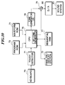
- Fig. 9 conceptually represents a manner of synthesizing musical tone data by means of software, which is employed by the computer music system according to the second embodiment.
- MIDI data read from the hard disk 7 or the floppy disk 8 is interpreted by a performance data-processing section 60, and then transmitted to the sound board 50.
- waveform data is read out from the wave table 21 by software, based on the MIDI data, to synthesize musical tone data from the waveform data.
- a WT tone generator section 62 of the sound board 50 waveform data is read out from a waveform table 51 by software, based on the MIDI data supplied from the host computer 30, and the musical tone data synthesized by the host computer 30 and the musical tone data synthesized by the sound board 50 are mixed together by a mixer 63 of the sound board 50, to thereby generate sound of the mixed musical tone.
- synthesization of musical tones is carried out by the sound board 50.
- the synthesization is carried out by the host computer 30.
- an improvement in the capacity such as an increase in the number of channels, can be easily attained.
- the number of channels employed in the second embodiment is identical with that of the first embodiment.
- the operation of the computer music system according to the second embodiment is similar to the first embodiment, except in that synthesization of musical tone data in the sound board 10, which is executed at the step S21 in Fig. 6, is carried out according to the musical tone-synthesizing program stored in the program memory 52. More specifically, an envelope of the musical tone is formed based on velocity data (velocity of key depression or key release) of the MIDI data, and an address of the wave table 51 is determined for determining which waveform data should be read out, based on a key code of the MIDI data. Then, the wave table 51 is accessed based on the above determined address, to read out corresponding waveform data. Then, the read-out waveform data is multiplied by the envelope, to thereby synthesize final waveform data (musical tone data).
- the host computer 30 does not only have a function of controlling empty channels but also a function of synthesizing musical tones by software.
- the sound board 50 has a function of synthesizing musical tones by software, in place of the tone generator LSI (hardware) employed in the first embodiment. Therefore, when the sound board 50 has no empty channel, the host computer 50 can synthesize musical tones. As a result, the whole processing capacity of the computer music system is improved, which makes it possible to efficiently synthesize musical tones, and also to increase the number of tone-generating channels and hence increase the number of musical tones which can be simultaneously generated.
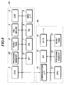
- Fig. 10 shows the arrangement of an electronic musical instrument according to the third embodiment.
- the electronic musical instrument is comprised of a keyboard 70, a touch detector 71, a panel switch/display section 72, a program ROM 73, a waveform ROM 74, a CPU 75, a sequential RAM 77, a tone generator LSI 78, an adder 79, a D/A converter 80, and a sound system 81.
- the keyboard 70 has a plurality of black keys and a plurality of white keys, to which the touch detector 71 is connected.
- the touch detector 71 detects the key-ON/OFF states and velocity of depression or release of each key, and supplies signals indicative of the sensed values to the CPU 75.
- the panel switch/display section 72 is comprised of panel switches for selecting performance-operating modes and tone colors of performance, and a display for displaying various kinds of information.
- the program ROM 73 stores programs, such as a musical tone-synthesizing program, according to which various component parts are controlled.
- the waveform ROM 74 stores waveform data, which are read out under control by the CPU 75 to synthesize musical tone data.
- the CPU 75 transmits performance data (MIDI data), which are to be synthesized for generation of musical tones, to the tone generator LSI 78, according to various kinds of information (key code, key-ON/OFF states, and velocity) from the touch detector 71 and information on settings by the panel switcher 72.
- the CPU 75 reads out waveform data from the waveform ROM 74 by using the sequential RAM 77 and supplies the read-out waveform data to the adder 79, according to the musical tone-synthesizing program stored in the program ROM 73.
- a function of synthesizing musical tones according to the above-mentioned musical tone-synthesizing program is represented by a WT (wave table) tone generator 76.
- the tone generator LSI 78 generates waveform data, based on the MIDI data supplied from the CPU 75, which is supplied to the adder 79. Whether waveform data indicative of a waveform of a musical tone is to be synthesized by the WT tone generator 76 or by the tone generator LSI 78 depends on the presence/absence of an empty channel in the tone generator LSI 78. That is, if the tone generator LSI 78 has no empty channel, waveform data is generated by the WT generator (software) 76.
- the adder 79 adds (mixes) together waveform data from the tone generator LSI 78 and waveform data from the WT tone generator 76 and supplies the mixed waveform data to the D/A converter 80.
- the D/A converter 80 converts the mixed waveform data to an analog signal and supplies the same to the sound system 81.
- the sound system 81 is comprised of an amplifier and a speaker, neither of which is shown, and converts the analog signal to a musical tone to generate musical sound.
- Figs. 11 and 12 show programs for synthesizing musical tones according to the third embodiment.
- initialization such as clearing of various registers used for giving performance
- key-event processing is executed.
- key-event processing when a key is depressed, assignment of a corresponding key code to a channel is carried out to determine whether a musical tone corresponding to the key is to be generated by the tone generator LSI 78 or by the WT tone generator 76, or when a key is released, generation of a corresponding musical tone is stopped to release the channel to which the musical tone is assigned. Details of the key-event processing will be described hereinafter.
- step S42 If assignment of a corresponding key code to a tone-generating channel has been made when a key is depressed, the program proceeds to a step S42, wherein inputting of information on settings by the panel switches 72, delivery of data to the display section 72, etc. are carried out. Then, at a step S43, musical tone data is synthesized by the WT tone generator 76 by the use of the waveform ROM 74, according to the musical tone-synthesizing program stored in the program ROM 73. If the key code is not assigned to a channel on the WT tone generator 76 side at the step S41, musical tone data is not synthesized by the WT tone generator 76. Then, the program returns to the step S41, and the steps S41 to S43 are repeatedly executed, to thereby synthesize musical tone data and carry out automatic performance, based on the synthesized musical tone data.
- a step S50 it is determined whether or not a key has been depressed, i.e. a key-on event has occurred. If a key-on event has occurred, the answer is affirmative (YES), and then the program proceeds to a step S51.
- step S51 it is determined whether or not the tone generator LSI 78 has an empty channel. If the tone generator LSI 78 has an empty channel, the answer is affirmative (YES), and then the program proceeds to a step S52.
- a key code (KC) of the depressed key is assigned to the empty channel in the tone generator LSI 78, and then at a step S53, the assigned channel (ch) and the key code (KC) are stored, and then the program returns to the main routine of Fig. 11, followed by executing the step S42.
- step S51 determines whether or not the WT tone generator 76 has an empty channel. If the WT tone generator 76 has an empty channel, the answer to the question of the step S54 is affirmative (YES), and then the program proceeds to a step S55, wherein the key code (KC) of the depressed key is assigned to the empty channel in the WT tone generator 76. Then, at the step S53, the assigned channel (ch) and the key code (KC) are stored, and then the program returns to the main routine of Fig. 11, followed by executing the step S42.
- KC key code
- the tone generator LSI 78 if the tone generator LSI 78 has an empty channel, a key code of a depressed key is assigned to the empty channel in the tone generator LSI 78, whereas if the tone generator LSI 78 has no empty channel, the key code is assigned to an empty channel in the WT tone generator 76.
- priority is given to the tone generator LSI 78 which synthesizes musical tones by hardware, and when all the channels in the tone generator LSI 78 are occupied, musical tones are synthesized by software on the WT tone generator side.
- the WT tone generator 76 has no empty channel, either, i.e. if the channels of the tone generator LSI 78 and the WT tone generator 76 are all occupied, the answer to the question of the step S54 is negative (NO), and then the program proceeds to a step, not shown, wherein sounding of the musical tone is inhibited, or alternatively a musical tone which is just decaying is stopped from being generated, to secure an empty cannel to which is then assigned the key code of the presently depressed key.
- step S50 If the performance data does not indicate a key-on event, i.e. it indicates a key-off event, the answer to the question of the step S50 is negative (NO), and then the program proceeds to a step S56.
- the assignment of the key code to the tone-generating channel is canceled based on the key code (KC) and the channel (ch) stored in the RAM 4, to release the channel from the assignment. Then, the program returns to the main routine, followed by executing the step S42.
- the electronic musical instrument according to the third embodiment has both the function of synthesizing musical tones by hardware (tone generator LSI 78) and the function of synthesizing musical tones by software (WT tone generator 76), and is constructed such that musical tones are preferentially synthesized by the tone generator LSI 78, while only when the tone generator LSI 78 has no empty channel, musical tones are synthesized by the WT tone generator 76 using software.
- the whole processing capacity of the electronic musical instrument is improved, which makes it possible to efficiently synthesize musical tones, and also to increase the number of tone-generating channels and hence increase the number of musical sounds which can be simultaneously generated.
- musical tone-synthesizing means which is given priority in synthesizing musical tones, e.g. a sound board, has no empty channel
- other musical tone-synthesizing means e.g. a host computer
- synthesizes musical tones this is not limitative.
- it may be arranged such that the two means synthesize musical tones having respective different characteristics, such as tone colors.
- a function of synthesizing simple musical tones such as rhythm sounds etc. may be allotted to a WT tone generator which synthesizes musical tones by software.
- a WT tone generator in general is suited for generating musical tones having such tone colors as can be generated simply by reading out PCM waveforms.
- musical tones (tone colors) requiring a complicated musical tone-synthesizing algorithm may be synthesized by the tone generator LSI.
- musical tones can be synthesized by means which are selected depending on characteristics of musical tones to be generated to thereby enable fully exhibiting these characteristics.
- the other musical tone-synthesizing means e.g. a host computer, is operated to synthesize musical tones.
- a subsystem of the computer music system normally synthesizes musical tones, however, if first musical tone-synthesizing means of the subsystem is in a predetermined state, second musical tone-synthesizing means of a main system of the computer music system synthesizes musical tones.
- first musical tone-synthesizing means of the subsystem is in a predetermined state
- second musical tone-synthesizing means of a main system of the computer music system synthesizes musical tones.
Abstract
Description
- This invention relates to a music system and an electronic musical instrument which reproduce automatic performance data such as MIDI (Musical Instrument Digital Interface) data.
- Conventionally, a computer music system, which is sometimes generically called an electronic musical instrument, is known, which reads out automatic performance data such as MIDI data stored in a floppy disk or a hard disk, and synthesizes musical tones according to the automatic performance data, by the use of an FM (frequency modulation) tone generator or a WT (wave table) tone generator, to thereby produce musical sounds.
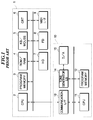
- Fig. 1 shows the arrangement of an example of the conventional computer music system. In the figure, the computer music system is comprised of an
ordinary host computer 1 as a main system, and asound board 10 as a subsystem connected to the main system via a predetermined interface. Thehost computer 1 has a construction similar to that of an ordinary personal computer, i.e. it is comprised of aCPU 2, aprogram memory 3, a ROM and aRAM 4, a keyboard and amouse 5, aCRT 6, ahard disk 7, afloppy disk 8, and anMIDI interface 9. - The
CPU 2 reads out performance data such as MIDI data from thehard disk 7 or thefloppy disk 8, which are provided as external memory devices, and transmits the performance data to thesound board 10 according to a program (program for automatic performance processing) stored in theprogram memory 3. The ROM andRAM 4 store a program for starting thehost computer 1, and various kinds of data used and/or obtained during execution of programs by theCPU 2. Further, thehost computer 1 can carry out preparation and edition of performance data by using the keyboard andmouse 5 and the CRT 6. Besides, theMIDI interface 9 takes in MIDI data from an external device, and sends out MIDI data to an external device. - On the other hand, the
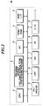
sound board 10 is comprised of aCPU 11, aprogram memory 12, acommunication interface 13, atone generator LSI 14, and a D/A converter 15. TheCPU 11 receives MIDI data from thehost computer 1 via thecommunication interface 13, generates musical tone data, based on the MIDI data by the use of thetone generator LSI 14, and converts the musical tone data to analog signals, to thereby generate musical tones by a loudspeaker, not shown, according to a program (program for automatic performance processing) stored in theprogram memory 12. - Fig. 2 shows the arrangement of another example of the conventional computer music system. In the figure, component parts corresponding to those in Fig. 1 are designated by identical numerals, and description thereof is omitted. The computer music system of Fig. 2 is comprised of an ordinary
personal computer 20, and distinguished from the example of Fig. 1 in that thepersonal computer 20 includes a wave table 21 which stores waveform data indicative of waveforms of musical tones, and a D/A converter 15. The system of Fig. 2 synthesizes and generates musical tones by itself. TheCPU 2 reads out performance data such as MIDI data from ahard disk 7 or afloppy disk 8, as external memory devices, then reads out waveform data from the wave table 21, based on the performance data, and converts the waveform data to analog signals, to thereby generate musical tones by a loudspeaker, not shown, according to a musical tone-synthesizing program stored in theprogram memory 3. In this example, theCPU 2 is capable of carrying out parallel processing, i.e. it can carry out other processings as well as synthesizing and generating musical tones. - Fig. 3 shows a program for synthesizing musical tones, which is executed by the above described computer music system of Fig. 2. At a step S1, performance data such as MIDI data are read out from the
hard disk 7 or thefloppy disk 8 and interpreted by theCPU 2. Then, at a step S2, it is determined whether or not the MIDI data indicates an ON-state or an OFF-state of any of keys on the keyboard. If the MIDI data does not indicate an ON-state or an OFF-state of a key, the answer is negative (NO), and then the program proceeds to a step, not shown, for executing processing corresponding to the data, description of which is omitted, since the processing is not related to the present invention. - On the other hand, if the MIDI data is key-ON data or key-OFF data, the answer to the question of the step S2 is affirmative (YES), and then the program proceeds to a step S3. At the step S3, a key code of the MIDI data is assigned to a tone-generating channel for generating a musical tone. In a computer music system of this kind, generally, a plurality of channels are provided, and therefore a plurality of musical tones can be simultaneously generated. Following the assignment of the channel, the program proceeds to a step S4, wherein an envelope of the musical tone is formed based on velocity data (velocity of key depression or key release) of the MIDI data. Then, at a step S5, an address in the wave table 21 is determined, which determines which waveform data should be read out, based on the key code of the MIDI data.
- Then, at a step S6, the wave table 21 is accessed based on the above determined address, to read out corresponding waveform data. At a step S7, the waveform data is multiplied by the envelope formed at the step S4 to prepare final waveform data (musical tone data), which in turn is delivered to the D/
A converter 15. The final waveform data is then converted to an analog signal by the D/A converter 15, followed by generating a musical tone by the loudspeaker. Then, the program proceeds to a step S8, wherein it is determined whether or not the automatic performance is to be terminated. If it is not to be terminated, the answer is negative (NO), and then the program returns to the step S1. On the other hand, if the automatic performance is to be terminated, the answer to the question of the step S8 is affirmative (YES), and then the automatic performance processing is terminated. In Fig. 3, the process of synthesizing a musical tone is expressed in a simplified (schematic) manner. However, the procedure from the step S4 to the step S7 for determining an instantaneous value of a musical tone waveform is repeatedly executed every predetermined sampling period until sounding of the musical tone is completed. - In the conventional computer music system of Fig. 1, which is comprised of the
host computer 1 and thesound board 10, all the functions relating to synthesization of musical tones are performed by thesound board 10. Therefore, the capacity of synthesizing musical tones, such as the number of tone-generating channels, is determined by the capacity of thesound board 10. For example, if performance data stored in thehard disk 7 or thefloppy disk 8 or performance data such as MIDI data supplied from an external device, etc. are designed for use by a tone generator with a larger capacity than the capacity of thesound board 10, thesound board 10 cannot fully process the performance data. Further, although in recent days a CPU which has an improved processing capacity (processing speed) has been used, the CPU is used only for controlling channels and preparing and editing performance data, resulting in insufficient utilization of the improved processing capacity. - Further, in the conventional computer music system of Fig. 2, which is comprised of the ordinary
personal computer 20 having the wave table 21, the synthesization of musical tones is entirely carried out by the use of software. Therefore, if, for example, the number of tone-generating channels is increased, an increased burden is imposed on the program, which adversely affects execution of the other processings which are executed in parallel with the synthesization by theCPU 2. Further, to avoid this inconvenience, merely a simple musical tone-synthesizing algorithm can be employed, resulting in degraded quality of sounds generated, compared with the quality of sounds generated by a system employing an exclusive sound board. - It is the object of the invention to provide a computer music system and an electronic musical instrument which afford easily improving the capacity of processing musical tones, such as increasing the number of tone-generating channels.
- To attain the object, the present invention provides a music system comprising a subsystem including a first musical tone-synthesizing device that synthesizes musical tones, based on performance data externally supplied thereto, and a mixing device that mixes together the musical tones synthesized by the first musical tone-synthesizing device and external musical tones externally generated and supplied thereto, and a main system including performance data-processing device that controls performance data indicative of musical tones to be performed and transmits the performance data to the subsystem at predetermined timing, and a second musical tone-synthesizing device that synthesizes musical tones, based on the performance data, when the first musical tone-synthesizing device is in a predetermined state, wherein the main system transmits the musical tones synthesized by the second musical tone-synthesizing device to the subsystem, as the external musical tones.
- Preferably, the second musical tone-synthesizing device synthesizes musical tones, based on the performance data, when the first musical tone-synthesizing device reaches a limit of processing capacity thereof.
- Advantageously, the first musical tone-synthesizing device synthesizes musical tones by hardware.
- Also advantageously, the first musical tone-synthesizing device and the second musical tone-synthesizing device operate in parallel to synthesize musical tones, based on the performance data.
- Preferably, the first musical tone-synthesizing device and the second musical tone-synthesizing device synthesize musical tones having respective different characteristics.
- To attain the same object, the present invention also provides an electronic music instrument comprising a performance data-processing device that controls performance data indicative of musical tones to be performed and transmits the performance data at predetermined timing, a first musical tone-synthesizing device that synthesizes musical tones, based on the performance data, a second musical tone-synthesizing device that synthesizes musical tones, based on the performance data, when the first musical tone-synthesizing device is in a predetermined state, a mixing device that mixes together the musical tones synthesized by the first musical tone-synthesizing device and the musical tones synthesized by the second musical tone-synthesizing device, and a sounding device that generates the musical tones mixed together by the mixing device.
- Preferably, the first musical tone-synthesizing device synthesizes musical tones by hardware, and the second musical tone-synthesizing device synthesizes musical tones by software.
- The above and other objects, features, and advantages of the invention will be more apparent from the following detailed description taken in conjunction with the accompanying drawings.
-
- Fig. 1 is a block diagram schematically showing the arrangement of a conventional computer music system;
- Fig. 2 is a block diagram schematically showing the arrangement of another conventional computer music system;
- Fig. 3 is a flowchart showing a program for synthesizing musical tones by the conventional computer music system in Fig. 2;
- Fig. 4 is a block diagram schematically showing the arrangement of a computer music system according to a first embodiment of the present invention;
- Fig. 5 is a view useful in explaining a manner of synthesizing musical tones according to the first embodiment;
- Fig. 6 is a flowchart showing a main routine for synthesizing musical tones, according to the first embodiment;
- Fig. 7 is a flowchart showing a subroutine for assigning key codes to tone-generating channels;
- Fig. 8 is a block diagram schematically showing the arrangement of a computer music system according to a second embodiment of the present invention;
- Fig. 9 is a view useful in explaining a manner of synthesizing musical tones according to the second embodiment;
- Fig. 10 is a block diagram schematically showing the arrangement of an electronic musical instrument according to a third embodiment of the invention;
- Fig. 11 is a flowchart showing a main routine for synthesizing musical tones, according to the third embodiment; and
- Fig. 12 is a flowchart showing a subroutine for carrying out key-event processing.
- The invention will now be described in detail with reference to the drawings showing embodiments thereof.
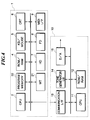
- Referring first to Fig. 4, there is schematically illustrated the whole arrangement of a computer music system according to a first embodiment of the invention. In Fig. 4, component parts corresponding to those in Figs. 1 and 2 are designated by identical numerals, and description thereof is omitted. The computer music system according to the first embodiment is comprised of a
host computer 30, and asound board 10 externally connected thereto. As shown in the figure, thehost computer 30 is comprised of a wave table 21 which stores waveform data indicative of waveforms of musical tones, and aprogram memory 22 which stores programs including a musical tone-synthesizing program for synthesizing musical tone data by reading out waveform data from the wave table 21, based on automatic performance data such as MIDI data. ACPU 2 operates on the musical tone-synthesizing program stored in theprogram memory 22 to read out automatic performance data such as MIDI data from ahard disk 7 or afloppy disk 8, which are provided as external memory devices, and transmit the read-out automatic performance data (MIDI data) to thesound board 10 when an empty channel is present on thesound board 10 side. On the other hand, when no empty channel is present on thesound board 10 side, theCPU 2 reads out waveform data from the wave table 21 provided in thehost computer 30, and transmits the read-out waveform data to thesound board 10. - On the other hand, the
sound board 10, which has a similar construction to that of the sound board of the conventional computer music system in Fig. 1, receives the MIDI data from thehost computer 30 via acommunication interface 13 and synthesizes musical tone data by means of atone generator LSI 14, according to a program stored in a ROM andRAM 12. Then, musical tone data synthesized by thehost computer 30 and musical tone data synthesized by thesound board 10 are mixed together, and the mixed musical tone data is converted to an analog signal by means of a D/A converter 15, whereby sound of a musical tone based on the mixed musical tone data is generated from a loudspeaker, not shown. In thesound board 10, most of processings with large burden are executed by thetone generator LSI 14, and therefore theCPU 11, the ROM andRAM 12, and the communication I/F 13 may be omitted from the construction of thesound board 10, if required. - Fig. 5 conceptually represents a manner of synthesizing musical tone data by means of software, which is employed by the computer music system according to the first embodiment. As shown in the figure, in the
host computer 30, MIDI data read from thehard disk 7 or thefloppy disk 8 is interpreted by a performance data-processingsection 40, and transmitted to thetone generator LSI 14 of thesound board 10. On this occasion, if required, at a WTtone generator section 41 of thehost computer 30, waveform data is read out from the wave table 21 by software, based on the MIDI data, to synthesize musical tone data from the waveform data. On the other hand, in thesound board 10, musical tone data is synthesized by the tone generator LSI (hardware) 14, based on MIDI data from thehost computer 30, and musical tone data synthesized by thehost computer 10 and musical tone data synthesized by thesound board 10 are mixed together by amixer 43 of thesound board 10, to thereby generate sound of the mixed musical tone. Normally, synthesization of musical tones is carried out by thesound board 10. However, when no empty channel is present in thesound board 10, the synthesization is carried out by thehost computer 30. As a result, an improvement in the capacity, such as an increase in the number of channels, can be easily attained. As shown in Fig. 5, according to the first embodiment, thehost computer 30 has three channels to which musical tone data can be assigned, while thesound board 10 has seven channels to which musical tone data can be assigned. - Next, the operation of the computer music system according to the first embodiment will be described with reference to Figs. 6 and 7 showing flowcharts of routines for synthesizing musical tones according to the first embodiment.
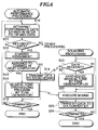
- First, at a step S10 in Fig. 6, in the
host computer 30, performance data such as MIDI data stored in thehard disk 7 or thefloppy disk 8 is read out and interpreted. Then, at a step S11, it is determined whether or not the MIDI data is key-ON data or key-OFF data. If the MIDI data is neither key-ON data nor key-OFF data, the answer is negative (NO), and then the program proceeds to a step, not shown, for executing a processing corresponding to the MIDI data, description of which is omitted. - On the other hand, if the MIDI data is key-ON data or key-OFF data, the answer to the question of the step S11 is affirmative (YES), and then the program proceeds to a step S12, wherein a key code of the MIDI data is assigned to a tone-generating channel for generating a musical tone. In this channel assignment processing, if there is an empty channel in the
sound board 10, the key code is assigned to the empty channel in thesound board 10. On the other hand, if there is no empty channel in thesound board 10, the key code is assigned to an empty channel in thehost computer 30. Details of the channel assignment processing will be described hereinafter. - Then, at a step S13, it is determined whether or not assignment of the key data to a channel in the
host computer 30 has been made. If assignment of the key data to a channel in thehost computer 30 has not been made, i.e. if assignment of the key data to a channel in thesound board 10 has been made, the answer is negative (NO), and then the program proceeds to a step S14. At the step S14, the MIDI data is transmitted via thecommunication interface 13 to thesound board 10. Then, it is determined at a step S16 whether or not the automatic performance is to be terminated. If it is not to be terminated, the answer is negative (NO), and then the program returns to the step S10. Thus, the steps S10 to S16 are repeatedly executed. In this manner, normally MIDI data are sequentially transmitted to thesound board 10. - On the other hand, in the
sound board 10, it is determined at a step S20 whether or not MIDI data has been received from thehost computer 30. If MIDI data has been received from thehost computer 30, the answer is affirmative (YES), and then the program proceeds to a step S21. At the step S21, musical tone data is synthesized based on the MIDI data by thetone generator LSI 14. Then, at a step S22, if musical tone data synthesized by thehost computer 30 has been transmitted to thesound board 10, the transmitted musical tone data and the musical tone data synthesized by thetone generator LSI 14 are mixed together. At a step S23, the mixed musical tone data is transmitted to the D/A converter 15, wherein the mixed musical tone data is converted to an analog signal, whereby musical sound is generated from the loudspeaker. - On the other hand, if there is no empty channel in the
sound board 10, the key data is assigned to a channel in thehost computer 30. In this case, the answer to the question of the step S13 is affirmative (YES), and then the program proceeds to a step S15. At the step S15, waveform data is synthesized based on the MIDI data according to the musical tone-synthesizing program stored in theprogram memory 22, and the synthesized waveform data is transmitted to thesound board 10. More specifically, an envelope of the musical tone is formed based on velocity data (velocity of key depression or key release) of the MIDI data, and then an address of the wave table 21 is determined for determining which waveform data should be read out, based on the key code of the MIDI data. Then, the wave table 21 is accessed based on the above determined address, to read out corresponding waveform data. Further, the read-out waveform data is multiplied by the envelope to thereby synthesize final waveform data (musical tone data), followed by transmitting the final waveform data to thesound board 10. Therefore, in this case, the musical tone data (waveform data) transmitted by thehost computer 30 at the step S22 and the musical tone data (waveform data) synthesized by thesound board 10 are mixed together, whereby a musical tone based on the mixed musical tone data is generated. - Next, description will be made of the channel assignment processing with reference to a subroutine shown in Fig. 7.
- At a step S30 in Fig. 7, it is determined by the
host computer 30 whether or not the read-out MIDI data indicates a key-ON event. If it indicates a key-ON event, the answer is affirmative (YES), and then the program proceeds to a step S31. At the step S31, it is determined whether or not an empty channel is present in thesound board 10 which is a subsystem of the computer music system. If thesound board 10 has an empty channel, the answer is affirmative (YES), and then the program proceeds to a step S32. At the step S32, the key code (KC) of the MIDI data is assigned to the empty channel in thesound board 10, and the assigned channel (ch) and the key code (KC) of the MIDI data are stored in theRAM 4 in thehost computer 30. Then, the program returns to the main routine of Fig. 6, followed by executing the step S13. - On the other hand, if no empty channel is present in the
sound board 10, the answer to the question of the step S31 is negative (NO), and then the program proceeds to a step S33. At the step S33, it is determined whether or not thehost computer 30 has an empty channel. If thehost computer 30 has no empty channel, i.e. if all the channels in thesound board 10 and thehost computer 30 are occupied, the answer is negative (NO). Then, the program proceeds to a step, not shown, wherein sounding of the musical tone is inhibited, or alternatively a musical tone which is just decaying is stopped from being generated, to secure an empty channel to which the key code data is to be assigned. - On the other hand, if the
host computer 30 has an empty channel, the answer to the question of the step S33 is affirmative (YES), and then the program proceeds to a step S34. At the step S34, the key code is assigned to the empty channel in thehost computer 30 as the tone-generating channel, and the assigned channel (ch) and the key code (KC) of the MIDI data are stored in theRAM 4 in thehost computer 30. Then, the program returns to the main routine, followed by executing the step S13. - If the MIDI data does not indicate a key-ON event, i.e. if the MIDI data indicates a key-OFF event, the answer to the question of the step S30 is negative (NO), and then the program proceeds to a step S35. At the step S35, the assignment of the key code to the tone-generating channel is canceled based on the key code (KC) and the channel (ch) stored in the
RAM 4, to release the channel from the assignment. Then, the program returns to the main routine, followed by executing the step S13. - As described above, according to the first embodiment, the
host computer 30 does not only have a function of controlling empty channels but also a function of synthesizing musical tones by software. Thus, when thesound board 10 has no empty channel, thehost computer 30 can synthesize musical tones. As a result, the processing capacity of the entire computer music system is improved, which makes it possible to efficiently synthesize musical tones, and also to increase the number of tone-generating channels and hence increase the number of musical tones which can be simultaneously generated. Besides, theCPU 2 in thehost computer 30 can be used for other processing (parallel processing). - Next, a second embodiment of the invention will be described with reference to Figs. 8 and 9.
- Fig. 8 shows the arrangement of a computer music system according to the second embodiment. In the figure, component parts corresponding to those in Fig. 4 are designated by identical numerals, and description thereof is omitted. The computer music system according to the second embodiment is comprised of a
host computer 30, and asound board 50 externally connected thereto, similarly to the first embodiment, and distinguished from the first embodiment in that thesound board 50 also has a wave table 51 which stores waveform data indicative of waveforms of musical tones, and aprogram memory 52 which stores a musical tone-synthesizing program for synthesizing musical tone data, based on MIDI data etc., by reading out waveform data from the wave table 51, similarly to thehost computer 30. That is, thesound board 50 also synthesizes musical tones by software, similarly to thehost computer 30. - Fig. 9 conceptually represents a manner of synthesizing musical tone data by means of software, which is employed by the computer music system according to the second embodiment. In the
host computer 30, MIDI data read from thehard disk 7 or thefloppy disk 8 is interpreted by a performance data-processingsection 60, and then transmitted to thesound board 50. On this occasion, if required, at a WTtone generator section 61 of thehost computer 30, waveform data is read out from the wave table 21 by software, based on the MIDI data, to synthesize musical tone data from the waveform data. On the other hand, at a WTtone generator section 62 of thesound board 50, waveform data is read out from a waveform table 51 by software, based on the MIDI data supplied from thehost computer 30, and the musical tone data synthesized by thehost computer 30 and the musical tone data synthesized by thesound board 50 are mixed together by amixer 63 of thesound board 50, to thereby generate sound of the mixed musical tone. Normally, synthesization of musical tones is carried out by thesound board 50. However, when no empty channel is present in thesound board 50, the synthesization is carried out by thehost computer 30. As a result, an improvement in the capacity, such as an increase in the number of channels, can be easily attained. The number of channels employed in the second embodiment is identical with that of the first embodiment. - The operation of the computer music system according to the second embodiment is similar to the first embodiment, except in that synthesization of musical tone data in the
sound board 10, which is executed at the step S21 in Fig. 6, is carried out according to the musical tone-synthesizing program stored in theprogram memory 52. More specifically, an envelope of the musical tone is formed based on velocity data (velocity of key depression or key release) of the MIDI data, and an address of the wave table 51 is determined for determining which waveform data should be read out, based on a key code of the MIDI data. Then, the wave table 51 is accessed based on the above determined address, to read out corresponding waveform data. Then, the read-out waveform data is multiplied by the envelope, to thereby synthesize final waveform data (musical tone data). - As described above, according to the second embodiment, the
host computer 30 does not only have a function of controlling empty channels but also a function of synthesizing musical tones by software. Further, thesound board 50 has a function of synthesizing musical tones by software, in place of the tone generator LSI (hardware) employed in the first embodiment. Therefore, when thesound board 50 has no empty channel, thehost computer 50 can synthesize musical tones. As a result, the whole processing capacity of the computer music system is improved, which makes it possible to efficiently synthesize musical tones, and also to increase the number of tone-generating channels and hence increase the number of musical tones which can be simultaneously generated. - Next, a third embodiment of the invention will be described with reference to Figs. 10 to 12.
- Fig. 10 shows the arrangement of an electronic musical instrument according to the third embodiment. The electronic musical instrument is comprised of a
keyboard 70, atouch detector 71, a panel switch/display section 72, aprogram ROM 73, awaveform ROM 74, aCPU 75, asequential RAM 77, atone generator LSI 78, anadder 79, a D/A converter 80, and asound system 81. - The
keyboard 70 has a plurality of black keys and a plurality of white keys, to which thetouch detector 71 is connected. Thetouch detector 71 detects the key-ON/OFF states and velocity of depression or release of each key, and supplies signals indicative of the sensed values to theCPU 75. The panel switch/display section 72 is comprised of panel switches for selecting performance-operating modes and tone colors of performance, and a display for displaying various kinds of information. - The
program ROM 73 stores programs, such as a musical tone-synthesizing program, according to which various component parts are controlled. Thewaveform ROM 74 stores waveform data, which are read out under control by theCPU 75 to synthesize musical tone data. TheCPU 75 transmits performance data (MIDI data), which are to be synthesized for generation of musical tones, to thetone generator LSI 78, according to various kinds of information (key code, key-ON/OFF states, and velocity) from thetouch detector 71 and information on settings by thepanel switcher 72. Further, theCPU 75 reads out waveform data from thewaveform ROM 74 by using thesequential RAM 77 and supplies the read-out waveform data to theadder 79, according to the musical tone-synthesizing program stored in theprogram ROM 73. In the figure, a function of synthesizing musical tones according to the above-mentioned musical tone-synthesizing program is represented by a WT (wave table) tone generator 76. - The
tone generator LSI 78 generates waveform data, based on the MIDI data supplied from theCPU 75, which is supplied to theadder 79. Whether waveform data indicative of a waveform of a musical tone is to be synthesized by the WT tone generator 76 or by thetone generator LSI 78 depends on the presence/absence of an empty channel in thetone generator LSI 78. That is, if thetone generator LSI 78 has no empty channel, waveform data is generated by the WT generator (software) 76. Theadder 79 adds (mixes) together waveform data from thetone generator LSI 78 and waveform data from the WT tone generator 76 and supplies the mixed waveform data to the D/A converter 80. The D/A converter 80 converts the mixed waveform data to an analog signal and supplies the same to thesound system 81. Thesound system 81 is comprised of an amplifier and a speaker, neither of which is shown, and converts the analog signal to a musical tone to generate musical sound. - Figs. 11 and 12 show programs for synthesizing musical tones according to the third embodiment.
- First, at a step S40 in Fig. 11, initialization, such as clearing of various registers used for giving performance, is executed. Then, at a step S41, key-event processing is executed. In the key-event processing, when a key is depressed, assignment of a corresponding key code to a channel is carried out to determine whether a musical tone corresponding to the key is to be generated by the
tone generator LSI 78 or by the WT tone generator 76, or when a key is released, generation of a corresponding musical tone is stopped to release the channel to which the musical tone is assigned. Details of the key-event processing will be described hereinafter. If assignment of a corresponding key code to a tone-generating channel has been made when a key is depressed, the program proceeds to a step S42, wherein inputting of information on settings by the panel switches 72, delivery of data to thedisplay section 72, etc. are carried out. Then, at a step S43, musical tone data is synthesized by the WT tone generator 76 by the use of thewaveform ROM 74, according to the musical tone-synthesizing program stored in theprogram ROM 73. If the key code is not assigned to a channel on the WT tone generator 76 side at the step S41, musical tone data is not synthesized by the WT tone generator 76. Then, the program returns to the step S41, and the steps S41 to S43 are repeatedly executed, to thereby synthesize musical tone data and carry out automatic performance, based on the synthesized musical tone data. - Then, the key-event processing outlined above will be described with reference to a subroutine shown in Fig. 12. First, at a step S50, it is determined whether or not a key has been depressed, i.e. a key-on event has occurred. If a key-on event has occurred, the answer is affirmative (YES), and then the program proceeds to a step S51. At the step S51, it is determined whether or not the
tone generator LSI 78 has an empty channel. If thetone generator LSI 78 has an empty channel, the answer is affirmative (YES), and then the program proceeds to a step S52. At the step S52, a key code (KC) of the depressed key is assigned to the empty channel in thetone generator LSI 78, and then at a step S53, the assigned channel (ch) and the key code (KC) are stored, and then the program returns to the main routine of Fig. 11, followed by executing the step S42. - On the other hand, if the tone generator LSI has no empty channel, the answer to the question of the step S51 is negative (NO), and then the program proceeds to a step S54, wherein it is determined whether or not the WT tone generator 76 has an empty channel. If the WT tone generator 76 has an empty channel, the answer to the question of the step S54 is affirmative (YES), and then the program proceeds to a step S55, wherein the key code (KC) of the depressed key is assigned to the empty channel in the WT tone generator 76. Then, at the step S53, the assigned channel (ch) and the key code (KC) are stored, and then the program returns to the main routine of Fig. 11, followed by executing the step S42.
- As described above, according to the key processing of the present embodiment, if the
tone generator LSI 78 has an empty channel, a key code of a depressed key is assigned to the empty channel in thetone generator LSI 78, whereas if thetone generator LSI 78 has no empty channel, the key code is assigned to an empty channel in the WT tone generator 76. In other words, priority is given to thetone generator LSI 78 which synthesizes musical tones by hardware, and when all the channels in thetone generator LSI 78 are occupied, musical tones are synthesized by software on the WT tone generator side. - On the other hand, if the WT tone generator 76 has no empty channel, either, i.e. if the channels of the
tone generator LSI 78 and the WT tone generator 76 are all occupied, the answer to the question of the step S54 is negative (NO), and then the program proceeds to a step, not shown, wherein sounding of the musical tone is inhibited, or alternatively a musical tone which is just decaying is stopped from being generated, to secure an empty cannel to which is then assigned the key code of the presently depressed key. - If the performance data does not indicate a key-on event, i.e. it indicates a key-off event, the answer to the question of the step S50 is negative (NO), and then the program proceeds to a step S56. At the step S56, the assignment of the key code to the tone-generating channel is canceled based on the key code (KC) and the channel (ch) stored in the
RAM 4, to release the channel from the assignment. Then, the program returns to the main routine, followed by executing the step S42. - As described above, the electronic musical instrument according to the third embodiment has both the function of synthesizing musical tones by hardware (tone generator LSI 78) and the function of synthesizing musical tones by software (WT tone generator 76), and is constructed such that musical tones are preferentially synthesized by the
tone generator LSI 78, while only when thetone generator LSI 78 has no empty channel, musical tones are synthesized by the WT tone generator 76 using software. As a result, the whole processing capacity of the electronic musical instrument is improved, which makes it possible to efficiently synthesize musical tones, and also to increase the number of tone-generating channels and hence increase the number of musical sounds which can be simultaneously generated. - In the above described first to third embodiments, when musical tone-synthesizing means which is given priority in synthesizing musical tones, e.g. a sound board, has no empty channel, other musical tone-synthesizing means, e.g. a host computer, synthesizes musical tones. However, this is not limitative. Alternatively or together with the above arrangement, it may be arranged such that the two musical tone-synthesizing means operate in parallel so that the both means always synthesize musical tones. Further alternatively, it may be arranged such that the two means synthesize musical tones having respective different characteristics, such as tone colors.
- The use of parallel processing as mentioned above provides an advantage such as increased applicability of the control by the electronic musical instrument. On the other hand, if the two means synthesize musical tones having respective different characteristics, musical tones can be generated in different manners suitable for respective different characteristic thereof.
- Especially, if the two means, e.g. a sound board and a host computer, synthesize musical tones having different characteristics, a function of synthesizing simple musical tones such as rhythm sounds etc. may be allotted to a WT tone generator which synthesizes musical tones by software. This is because a WT tone generator in general is suited for generating musical tones having such tone colors as can be generated simply by reading out PCM waveforms. On the other hand, musical tones (tone colors) requiring a complicated musical tone-synthesizing algorithm may be synthesized by the tone generator LSI. Thus, musical tones can be synthesized by means which are selected depending on characteristics of musical tones to be generated to thereby enable fully exhibiting these characteristics. Therefore, only when the sound board is in a predetermined state, e.g. when no empty channel is present or when special musical tones are to be generated, the other musical tone-synthesizing means, e.g. a host computer, is operated to synthesize musical tones.
- As described above in detail, according to the invention, a subsystem of the computer music system normally synthesizes musical tones, however, if first musical tone-synthesizing means of the subsystem is in a predetermined state, second musical tone-synthesizing means of a main system of the computer music system synthesizes musical tones. As a result, the number of musical tones which can be simultaneously generated can be increased, to thereby enable easily improving the processing capacity of the system.
Claims (10)
- A music system comprising:
a subsystem including a first musical tone-synthesizing device that synthesizes musical tones, based on performance data externally supplied thereto, and a mixing device that mixes together said musical tones synthesized by said first musical tone-synthesizing device and external musical tones externally generated and supplied thereto; anda main system including performance data-processing device that controls performance data indicative of musical tones to be performed and transmits said performance data to said subsystem at predetermined timing, and a second musical tone-synthesizing device that synthesizes musical tones, based on said performance data, when said first musical tone-synthesizing device is in a predetermined state;wherein said main system transmits said musical tones synthesized by said second musical tone-synthesizing device to said subsystem, as said external musical tones. - A music system as claimed in claim 1, wherein said second musical tone-synthesizing device synthesizes musical tones, based on said performance data, when said first musical tone-synthesizing device reaches a limit of processing capacity thereof.
- A music system as claimed in claim 1 or 2, wherein said first musical tone-synthesizing device synthesizes musical tones by hardware.
- A music system as claimed in claim 1 or 2, wherein said first musical tone-synthesizing device and said second musical tone-synthesizing device operate in parallel to synthesize musical tones, based on said performance data.
- A music system as claimed in claim 4, wherein said first musical tone-synthesizing device and said second musical tone-synthesizing device synthesize musical tones having respective different characteristics.
- An electronic music instrument comprising:a performance data-processing device that controls performance data indicative of musical tones to be performed and transmits said performance data at predetermined timing;a first musical tone-synthesizing device that synthesizes musical tones, based on said performance data;a second musical tone-synthesizing device that synthesizes musical tones, based on said performance data, when said first musical tone-synthesizing device is in a predetermined state;a mixing device that mixes together said musical tones synthesized by said first musical tone-synthesizing device and said musical tones synthesized by said second musical tone-synthesizing device; anda sounding device that generates said musical tones mixed together by said mixing device.
- An electronic music instrument as claimed in claim 6, wherein said second musical tone-synthesizing device synthesizes musical tones, based on said performance data, when said first musical tone-synthesizing device reaches a limit of processing capacity thereof.
- An electronic music instrument as claimed in in claim 6 or 7, wherein said first musical tone-synthesizing device synthesizes musical tones by hardware, and said second musical tone-synthesizing device synthesizes musical tones by software.
- An electronic music instrument as claimed in claim 6 or 7, wherein said first musical tone-synthesizing device and said second musical tone-synthesizing device operate in parallel to synthesize musical tones, based on said performance data, and wherein preferably said first musical tone-synthesizing device and said second musical tone-synthesizing device synthesize musical tones having respective characteristics.
- A music system comprising:a subsystem including a first musical tonbe-synthesizing device; anda main system including a second musical tone-synthesizing device;wherein said main system transmits said musical tones synthesized by said second musical tone-synthesizing device to said subsystem.
Applications Claiming Priority (3)
| Application Number | Priority Date | Filing Date | Title |
|---|---|---|---|
| JP124055/95 | 1995-05-23 | ||
| JP12405595A JP3223756B2 (en) | 1995-05-23 | 1995-05-23 | Music systems and electronic musical instruments |
| JP12405595 | 1995-05-23 |
Publications (3)
| Publication Number | Publication Date |
|---|---|
| EP0744733A2 true EP0744733A2 (en) | 1996-11-27 |
| EP0744733A3 EP0744733A3 (en) | 1997-01-15 |
| EP0744733B1 EP0744733B1 (en) | 2001-09-19 |
Family
ID=14875861
Family Applications (1)
| Application Number | Title | Priority Date | Filing Date |
|---|---|---|---|
| EP96108169A Expired - Lifetime EP0744733B1 (en) | 1995-05-23 | 1996-05-22 | Electronic musical instrument |
Country Status (6)
| Country | Link |
|---|---|
| US (1) | US5750913A (en) |
| EP (1) | EP0744733B1 (en) |
| JP (1) | JP3223756B2 (en) |
| DE (1) | DE69615268T2 (en) |
| SG (1) | SG46734A1 (en) |
| TW (1) | TW411435B (en) |
Cited By (1)
| Publication number | Priority date | Publication date | Assignee | Title |
|---|---|---|---|---|
| EP1271467A1 (en) * | 2000-03-28 | 2003-01-02 | Yamaha Corporation | Music player applicable to portable telephone terminal |
Families Citing this family (7)
| Publication number | Priority date | Publication date | Assignee | Title |
|---|---|---|---|---|
| US5898125A (en) * | 1995-10-17 | 1999-04-27 | Foster-Miller, Inc. | Ballistically deployed restraining net |
| US6069311A (en) * | 1997-05-22 | 2000-05-30 | Yamaha Corporation | Electronic musical instrument having mother board communicable with plug-in board |
| JP2000029462A (en) * | 1998-05-18 | 2000-01-28 | Sony Corp | Information processor, information processing method, and providing medium |
| FR2781147B1 (en) | 1998-07-20 | 2000-09-15 | Oreal | COMPOSITIONS FOR DYEING KERATINIC FIBERS CONTAINING 3-AMINO PYRAZOLINE DERIVATIVES AS A COUPLER, DYEING METHOD AND DYEING KIT |
| TWI227010B (en) * | 2003-05-23 | 2005-01-21 | Mediatek Inc | Wavetable audio synthesis system |
| JP2006053170A (en) * | 2004-07-14 | 2006-02-23 | Yamaha Corp | Electronic music apparatus and program for realizing control method thereof |
| JP4623060B2 (en) * | 2007-07-18 | 2011-02-02 | ヤマハ株式会社 | Waveform generating device, sound effect applying device, and musical sound generating device |
Citations (4)
| Publication number | Priority date | Publication date | Assignee | Title |
|---|---|---|---|---|
| EP0126962A2 (en) * | 1983-05-21 | 1984-12-05 | Reinhard Franz | Electronic keyboard musical instrument, and device for using it |
| US5200564A (en) * | 1990-06-29 | 1993-04-06 | Casio Computer Co., Ltd. | Digital information processing apparatus with multiple CPUs |
| US5376750A (en) * | 1991-12-24 | 1994-12-27 | Yamaha Corporation | Electronic musical instrument having working RAM controlled by plural CPUs |
| US5446237A (en) * | 1992-01-08 | 1995-08-29 | Yamaha Corporation | Electronic musical instrument having a control section memory for generating musical tone parameters |
Family Cites Families (5)
| Publication number | Priority date | Publication date | Assignee | Title |
|---|---|---|---|---|
| US5119710A (en) * | 1986-03-09 | 1992-06-09 | Nippon Gakki Seizo Kabushiki Kaisha | Musical tone generator |
| US5020410A (en) * | 1988-11-24 | 1991-06-04 | Casio Computer Co., Ltd. | Sound generation package and an electronic musical instrument connectable thereto |
| US5198603A (en) * | 1989-08-19 | 1993-03-30 | Roland Corporation | Automatic data-prereading playing apparatus and sound generating unit in an automatic musical playing system |
| JP2671690B2 (en) * | 1992-01-08 | 1997-10-29 | ヤマハ株式会社 | Electronic musical instrument |
| JP2882311B2 (en) * | 1995-06-07 | 1999-04-12 | ヤマハ株式会社 | Music system, sound source and tone synthesis method |
-
1995
- 1995-05-23 JP JP12405595A patent/JP3223756B2/en not_active Expired - Fee Related
-
1996
- 1996-05-22 EP EP96108169A patent/EP0744733B1/en not_active Expired - Lifetime
- 1996-05-22 DE DE69615268T patent/DE69615268T2/en not_active Expired - Lifetime
- 1996-05-22 SG SG1996009862A patent/SG46734A1/en unknown
- 1996-05-22 US US08/653,939 patent/US5750913A/en not_active Expired - Lifetime
- 1996-05-24 TW TW085106187A patent/TW411435B/en not_active IP Right Cessation
Patent Citations (4)
| Publication number | Priority date | Publication date | Assignee | Title |
|---|---|---|---|---|
| EP0126962A2 (en) * | 1983-05-21 | 1984-12-05 | Reinhard Franz | Electronic keyboard musical instrument, and device for using it |
| US5200564A (en) * | 1990-06-29 | 1993-04-06 | Casio Computer Co., Ltd. | Digital information processing apparatus with multiple CPUs |
| US5376750A (en) * | 1991-12-24 | 1994-12-27 | Yamaha Corporation | Electronic musical instrument having working RAM controlled by plural CPUs |
| US5446237A (en) * | 1992-01-08 | 1995-08-29 | Yamaha Corporation | Electronic musical instrument having a control section memory for generating musical tone parameters |
Cited By (2)
| Publication number | Priority date | Publication date | Assignee | Title |
|---|---|---|---|---|
| EP1271467A1 (en) * | 2000-03-28 | 2003-01-02 | Yamaha Corporation | Music player applicable to portable telephone terminal |
| EP1271467A4 (en) * | 2000-03-28 | 2008-09-03 | Yamaha Corp | Music player applicable to portable telephone terminal |
Also Published As
| Publication number | Publication date |
|---|---|
| DE69615268D1 (en) | 2001-10-25 |
| SG46734A1 (en) | 1998-02-20 |
| EP0744733B1 (en) | 2001-09-19 |
| JPH08314450A (en) | 1996-11-29 |
| TW411435B (en) | 2000-11-11 |
| JP3223756B2 (en) | 2001-10-29 |
| EP0744733A3 (en) | 1997-01-15 |
| US5750913A (en) | 1998-05-12 |
| DE69615268T2 (en) | 2002-06-13 |
Similar Documents
| Publication | Publication Date | Title |
|---|---|---|
| US5020410A (en) | Sound generation package and an electronic musical instrument connectable thereto | |
| US5698802A (en) | Music system, tone generator and musical tone-synthesizing method | |
| US5750913A (en) | Music system and electronic musical instrument | |
| JP3707300B2 (en) | Expansion board for musical sound generator | |
| US6303852B1 (en) | Apparatus and method for synthesizing musical tones using extended tone color settings | |
| US5414209A (en) | Electronic musical instrument | |
| US8373055B2 (en) | Apparatus, method and computer program for switching musical tone output | |
| US5428183A (en) | Tone signal generating apparatus for performing a timbre change by storing a full frequency band in a wave memory | |
| US6069311A (en) | Electronic musical instrument having mother board communicable with plug-in board | |
| US5074183A (en) | Musical-tone-signal-generating apparatus having mixed tone color designation states | |
| US6351475B1 (en) | Mixing apparatus with compatible multiplexing of internal and external voice signals | |
| JP3780695B2 (en) | Effect adding device and sound effect setting method | |
| JP3721789B2 (en) | Mixing equipment | |
| JP2699652B2 (en) | Music signal generator | |
| JP3092588B2 (en) | Music generator | |
| JP2570819B2 (en) | Electronic musical instrument | |
| JP3650526B2 (en) | Automatic performance device and storage medium | |
| JP3687317B2 (en) | Music generator | |
| JP3700605B2 (en) | Music signal processor | |
| JP2626242B2 (en) | Music signal generator | |
| JP2570945B2 (en) | Tone generator | |
| JP3442232B2 (en) | Electronic musical instrument | |
| US5426261A (en) | Musical tone control waveform signal generating apparatus utilizing waveform data parameters in time-division intervals | |
| JP2715003B2 (en) | Electronic musical instrument | |
| JPH0934455A (en) | Electronic musical instrument |
Legal Events
| Date | Code | Title | Description |
|---|---|---|---|
| PUAI | Public reference made under article 153(3) epc to a published international application that has entered the european phase |
Free format text: ORIGINAL CODE: 0009012 |
|
| AK | Designated contracting states |
Kind code of ref document: A2 Designated state(s): DE FR GB |
|
| PUAL | Search report despatched |
Free format text: ORIGINAL CODE: 0009013 |
|
| AK | Designated contracting states |
Kind code of ref document: A3 Designated state(s): DE FR GB |
|
| 17P | Request for examination filed |
Effective date: 19970711 |
|
| 17Q | First examination report despatched |
Effective date: 20000315 |
|
| GRAG | Despatch of communication of intention to grant |
Free format text: ORIGINAL CODE: EPIDOS AGRA |
|
| GRAG | Despatch of communication of intention to grant |
Free format text: ORIGINAL CODE: EPIDOS AGRA |
|
| GRAH | Despatch of communication of intention to grant a patent |
Free format text: ORIGINAL CODE: EPIDOS IGRA |
|
| GRAH | Despatch of communication of intention to grant a patent |
Free format text: ORIGINAL CODE: EPIDOS IGRA |
|
| GRAA | (expected) grant |
Free format text: ORIGINAL CODE: 0009210 |
|
| AK | Designated contracting states |
Kind code of ref document: B1 Designated state(s): DE FR GB |
|
| REF | Corresponds to: |
Ref document number: 69615268 Country of ref document: DE Date of ref document: 20011025 |
|
| REG | Reference to a national code |
Ref country code: GB Ref legal event code: IF02 |
|
| ET | Fr: translation filed | ||
| PLBE | No opposition filed within time limit |
Free format text: ORIGINAL CODE: 0009261 |
|
| STAA | Information on the status of an ep patent application or granted ep patent |
Free format text: STATUS: NO OPPOSITION FILED WITHIN TIME LIMIT |
|
| 26N | No opposition filed | ||
| PGFP | Annual fee paid to national office [announced via postgrant information from national office to epo] |
Ref country code: FR Payment date: 20110523 Year of fee payment: 16 |
|
| PGFP | Annual fee paid to national office [announced via postgrant information from national office to epo] |
Ref country code: GB Payment date: 20110518 Year of fee payment: 16 |
|
| PGFP | Annual fee paid to national office [announced via postgrant information from national office to epo] |
Ref country code: DE Payment date: 20110518 Year of fee payment: 16 |
|
| GBPC | Gb: european patent ceased through non-payment of renewal fee |
Effective date: 20120522 |
|
| REG | Reference to a national code |
Ref country code: FR Ref legal event code: ST Effective date: 20130131 |
|
| REG | Reference to a national code |
Ref country code: DE Ref legal event code: R119 Ref document number: 69615268 Country of ref document: DE Effective date: 20121201 |
|
| PG25 | Lapsed in a contracting state [announced via postgrant information from national office to epo] |
Ref country code: GB Free format text: LAPSE BECAUSE OF NON-PAYMENT OF DUE FEES Effective date: 20120522 Ref country code: FR Free format text: LAPSE BECAUSE OF NON-PAYMENT OF DUE FEES Effective date: 20120531 |
|
| PG25 | Lapsed in a contracting state [announced via postgrant information from national office to epo] |
Ref country code: DE Free format text: LAPSE BECAUSE OF NON-PAYMENT OF DUE FEES Effective date: 20121201 |