EP0743704B1 - Method and apparatus for mounting an electrical connector on a printed wiring board - Google Patents
Method and apparatus for mounting an electrical connector on a printed wiring board Download PDFInfo
- Publication number
- EP0743704B1 EP0743704B1 EP96107767A EP96107767A EP0743704B1 EP 0743704 B1 EP0743704 B1 EP 0743704B1 EP 96107767 A EP96107767 A EP 96107767A EP 96107767 A EP96107767 A EP 96107767A EP 0743704 B1 EP0743704 B1 EP 0743704B1
- Authority
- EP
- European Patent Office
- Prior art keywords
- projection
- connector
- substrate
- fastening means
- eyelet
- Prior art date
- Legal status (The legal status is an assumption and is not a legal conclusion. Google has not performed a legal analysis and makes no representation as to the accuracy of the status listed.)
- Expired - Lifetime
Links
Images


Classifications
-
- H—ELECTRICITY
- H01—ELECTRIC ELEMENTS
- H01R—ELECTRICALLY-CONDUCTIVE CONNECTIONS; STRUCTURAL ASSOCIATIONS OF A PLURALITY OF MUTUALLY-INSULATED ELECTRICAL CONNECTING ELEMENTS; COUPLING DEVICES; CURRENT COLLECTORS
- H01R12/00—Structural associations of a plurality of mutually-insulated electrical connecting elements, specially adapted for printed circuits, e.g. printed circuit boards [PCB], flat or ribbon cables, or like generally planar structures, e.g. terminal strips, terminal blocks; Coupling devices specially adapted for printed circuits, flat or ribbon cables, or like generally planar structures; Terminals specially adapted for contact with, or insertion into, printed circuits, flat or ribbon cables, or like generally planar structures
- H01R12/70—Coupling devices
- H01R12/7005—Guiding, mounting, polarizing or locking means; Extractors
- H01R12/7011—Locking or fixing a connector to a PCB
- H01R12/7047—Locking or fixing a connector to a PCB with a fastener through a screw hole in the coupling device
-
- H—ELECTRICITY
- H01—ELECTRIC ELEMENTS
- H01R—ELECTRICALLY-CONDUCTIVE CONNECTIONS; STRUCTURAL ASSOCIATIONS OF A PLURALITY OF MUTUALLY-INSULATED ELECTRICAL CONNECTING ELEMENTS; COUPLING DEVICES; CURRENT COLLECTORS
- H01R43/00—Apparatus or processes specially adapted for manufacturing, assembling, maintaining, or repairing of line connectors or current collectors or for joining electric conductors
- H01R43/20—Apparatus or processes specially adapted for manufacturing, assembling, maintaining, or repairing of line connectors or current collectors or for joining electric conductors for assembling or disassembling contact members with insulating base, case or sleeve
- H01R43/205—Apparatus or processes specially adapted for manufacturing, assembling, maintaining, or repairing of line connectors or current collectors or for joining electric conductors for assembling or disassembling contact members with insulating base, case or sleeve with a panel or printed circuit board
-
- H—ELECTRICITY
- H05—ELECTRIC TECHNIQUES NOT OTHERWISE PROVIDED FOR
- H05K—PRINTED CIRCUITS; CASINGS OR CONSTRUCTIONAL DETAILS OF ELECTRIC APPARATUS; MANUFACTURE OF ASSEMBLAGES OF ELECTRICAL COMPONENTS
- H05K3/00—Apparatus or processes for manufacturing printed circuits
- H05K3/30—Assembling printed circuits with electric components, e.g. with resistors
- H05K3/306—Assembling printed circuits with electric components, e.g. with resistors with lead-in-hole components
-
- Y—GENERAL TAGGING OF NEW TECHNOLOGICAL DEVELOPMENTS; GENERAL TAGGING OF CROSS-SECTIONAL TECHNOLOGIES SPANNING OVER SEVERAL SECTIONS OF THE IPC; TECHNICAL SUBJECTS COVERED BY FORMER USPC CROSS-REFERENCE ART COLLECTIONS [XRACs] AND DIGESTS
- Y10—TECHNICAL SUBJECTS COVERED BY FORMER USPC
- Y10T—TECHNICAL SUBJECTS COVERED BY FORMER US CLASSIFICATION
- Y10T29/00—Metal working
- Y10T29/49—Method of mechanical manufacture
- Y10T29/49002—Electrical device making
- Y10T29/49117—Conductor or circuit manufacturing
- Y10T29/49124—On flat or curved insulated base, e.g., printed circuit, etc.
- Y10T29/4913—Assembling to base an electrical component, e.g., capacitor, etc.
- Y10T29/49139—Assembling to base an electrical component, e.g., capacitor, etc. by inserting component lead or terminal into base aperture
-
- Y—GENERAL TAGGING OF NEW TECHNOLOGICAL DEVELOPMENTS; GENERAL TAGGING OF CROSS-SECTIONAL TECHNOLOGIES SPANNING OVER SEVERAL SECTIONS OF THE IPC; TECHNICAL SUBJECTS COVERED BY FORMER USPC CROSS-REFERENCE ART COLLECTIONS [XRACs] AND DIGESTS
- Y10—TECHNICAL SUBJECTS COVERED BY FORMER USPC
- Y10T—TECHNICAL SUBJECTS COVERED BY FORMER US CLASSIFICATION
- Y10T29/00—Metal working
- Y10T29/49—Method of mechanical manufacture
- Y10T29/49002—Electrical device making
- Y10T29/49117—Conductor or circuit manufacturing
- Y10T29/49124—On flat or curved insulated base, e.g., printed circuit, etc.
- Y10T29/49147—Assembling terminal to base
-
- Y—GENERAL TAGGING OF NEW TECHNOLOGICAL DEVELOPMENTS; GENERAL TAGGING OF CROSS-SECTIONAL TECHNOLOGIES SPANNING OVER SEVERAL SECTIONS OF THE IPC; TECHNICAL SUBJECTS COVERED BY FORMER USPC CROSS-REFERENCE ART COLLECTIONS [XRACs] AND DIGESTS
- Y10—TECHNICAL SUBJECTS COVERED BY FORMER USPC
- Y10T—TECHNICAL SUBJECTS COVERED BY FORMER US CLASSIFICATION
- Y10T29/00—Metal working
- Y10T29/49—Method of mechanical manufacture
- Y10T29/49002—Electrical device making
- Y10T29/49117—Conductor or circuit manufacturing
- Y10T29/49124—On flat or curved insulated base, e.g., printed circuit, etc.
- Y10T29/49147—Assembling terminal to base
- Y10T29/49151—Assembling terminal to base by deforming or shaping
- Y10T29/49153—Assembling terminal to base by deforming or shaping with shaping or forcing terminal into base aperture
-
- Y—GENERAL TAGGING OF NEW TECHNOLOGICAL DEVELOPMENTS; GENERAL TAGGING OF CROSS-SECTIONAL TECHNOLOGIES SPANNING OVER SEVERAL SECTIONS OF THE IPC; TECHNICAL SUBJECTS COVERED BY FORMER USPC CROSS-REFERENCE ART COLLECTIONS [XRACs] AND DIGESTS
- Y10—TECHNICAL SUBJECTS COVERED BY FORMER USPC
- Y10T—TECHNICAL SUBJECTS COVERED BY FORMER US CLASSIFICATION
- Y10T29/00—Metal working
- Y10T29/53—Means to assemble or disassemble
- Y10T29/5313—Means to assemble electrical device
- Y10T29/53174—Means to fasten electrical component to wiring board, base, or substrate
-
- Y—GENERAL TAGGING OF NEW TECHNOLOGICAL DEVELOPMENTS; GENERAL TAGGING OF CROSS-SECTIONAL TECHNOLOGIES SPANNING OVER SEVERAL SECTIONS OF THE IPC; TECHNICAL SUBJECTS COVERED BY FORMER USPC CROSS-REFERENCE ART COLLECTIONS [XRACs] AND DIGESTS
- Y10—TECHNICAL SUBJECTS COVERED BY FORMER USPC
- Y10T—TECHNICAL SUBJECTS COVERED BY FORMER US CLASSIFICATION
- Y10T29/00—Metal working
- Y10T29/53—Means to assemble or disassemble
- Y10T29/5313—Means to assemble electrical device
- Y10T29/53174—Means to fasten electrical component to wiring board, base, or substrate
- Y10T29/53183—Multilead component
Definitions
- the present invention relates to electrical connectors and more particularly to methods and apparatus for attaching electrical connectors to a substrate.
- the method as described above for fixing a connector to a printed wiring board has several disadvantages.
- the conventional method as described above involves two distinct procedures in that the eyelet is not attached to the connector and the wiring board until the signal pins have first been aligned with them and inserted into the pin receiving apertures. The carrying out of these two distinct procedures may result in a significant addition to the time and expense required for the overall assembly operation.
- US patent No. 4,884,336 discloses a method for mounting an electrical connector to a printed circuit board with a top actuated eyelet.
- the connector is mounted in a two-step process, whereby the actuating tool first grips and restrains the connector and thereafter the connector is positioned relative to a printed circuit board, and the tool is operated to actuate the eyelet to attach the connector to the board.
- the method permits the eyelet to be used to facilitate positioning of the connector on the printed circuit board.
- European patent application EP 0 598 492 A1 discloses a further method and apparatus for mounting connectors. According to this method, the circuit boards are aligned with the connectors by inserting string loaded pins through holes in the board. The connectors are then mounted by inserting pegs on the connector housing through the same holes which include the pins. The pins are displaced from the holes as the pegs are inserted therein while alignment is maintained.
- the present invention provides an assembly for mounting an electrical connector on a substrate wherein the connector comprises a plurality of pins and at least one fastening means; the substrate includes a plurality of pin receiving apertures for receiving the connector pins and at least one aperture for receiving said fastening means and the assembly includes a tooling plate for receiving the substrate, and a projection extending from said tooling plate or through said tooling plate and adapted to be received in the fastening means receiving aperture of the substrate characterized in that said connector further comprises at least one hold down means having an aperture in which said fastening means is disposed; said projection is adapted to be received in the aperture of the connector for locating the connector with respect to the substrate; and the projection and/or the tooling plate comprises deformation means for deforming the fastening means for causing the fastening means to secure the connector onto the substrate as the pins of the connector are inserted into the pin receiving apertures in the substrate.
- the present invention further provides a method of mounting an electrical connector on a substrate, said connector having a plurality of pins and at least one fastening means, comprising the steps of positioning a substrate having pin receiving means, comprising a plurality of pin receiving apertures, and at least one fastening means receiving aperture in the substrate, adjacent to a tooling plate, wherein a projection is extending from or through said tooling plate, such that the projection is aligned with the aperture on the substrate positioning the connector such that the fastening means is aligned with said projection; initially engaging the hold down means with the projection characterized in that: Said connector further comprises hold down means with an aperture having said fastening means disposed therein, and said projection and or, said tooling plate comprises a means for deforming the fastening means, wherein said method further comprises engaging said fastening means with the projection until the connector pins engage the pin receiving means in the substrate; and causing said fastening means to secure the connector onto the substrate by engaging the fastening means by said deformation, as the pins of the
- the hold down apertures of the connectors are first superimposed and aligned with location projections which extend perpendicularly upwardly from a tooling plate.
- the connector is then lowered toward the tooling plate until the hold down apertures are initially engaged with the tooling projection. Downward motion of the connectors continues until the pins first engage then are seated in the pin receiving apertures in the printed wiring board and the hold down apertures are fully engaged with the locating projection.
- An axial force is then applied downwardly to the eyelet against a deformation means in the tooling plate to bend the eyelet to engage the printed wiring board within its thickness and on its lower side.
- the eyelet also engages the connector on its upper side so as to fix the connector to the printed wiring board.
- eyelet what is meant is any type of tubular rivet or other fastener which can concentrically engage a projection that fits through an aperture.
- a connector is shown generally at numeral 10.
- This connector includes a receptacle 12, a guide pin 14, a mounting bracket 16, a press block 18 and an end wall 20 positioned between the bracket and the press block. It will be understood that there is shown only one end of the connector and at the other end there will be a similarly positioned and essentially identical mounting bracket and guide pin. It will also be seen that the mounting bracket includes a hold down aperture 22 in which there is positioned an annular rivet which is also commonly referred to as an eyelet 24. Signal pins as at 26 and 28 extend downwardly from the press block.
- a preferred embodiment of the method of the present invention is illustrated in greater detail.
- a tooling plate 30 which has an upwardly extending perpendicular locating projectile 32 along with deformation recesses as at 34 and 36.
- deformation recesses as at 34 and 36.
- a printed wiring board 38 having a pair of apertures as at 40 is positioned so that the apertures are engaged with the locating projections of the tooling plate and the printed wiring board abuts the tooling plate in side to side relation.
- the connector is then superimposed over the printed wiring board and the tooling plate so that it's hold down apertures and the concentric eyelet are in vertical alignment with the locating projections at the tooling plate.
- the eyelet is initially engaged with the locating projection as is shown in Fig. 3c. It will be noted from Fig. 3c that upon the initial engagement of the hold down aperture and the eyelet with the locating projection that the pins of the connectors are not yet engaged with a respective pin receiving aperture in the printed wiring board.
- additional tooling is then provided by way of an eyelet support block 42 which is superimposed above the mounting bracket and in particular the hold down aperture and the eyelet.
- the eyelet support block has a vertical bore 56 with a rivet receiving recess 58 on its lower side.
- the locating projection has an upper nipple 60 and a lower axially expanded deformation section 62. Outwardly from this deformation section there is an annular collar 64. Beneath the locating projection in the tooling plate there is also an axial bore 66 in which there is a plug 68 which is at the upper end of a spring 70 which is attached at its lower end to a projection spring base 72.
- the eyelet 24 is positioned over the nipple of the locating projection and is retained at its lower end between that nipple and the annular collar and at its upper end in the recess of the eyelet support block.
- As downward axial pressure is applied to the eyelet its lower section is deformed outwardly by the lower flared deformation section of the locating projection. That lower portion is received in the deformation recesses so that a crimp is formed as at shown at numeral 55 in Fig. 4. While such downward axial pressure is applied to the eyelet, spring 70 is compressed in the axial bore 66. After the lower end of the rivet has been crimped and the downward axial pressure is removed the spring expands to at least partially remove the printed wiring board from the locating projection.
- a connector shown generally at numeral 110 and being essentially identical to those shown in Fig. 1 and 2 has been positioned with a eyelet 124 on an upper tooling plate 130 with a perpendicular locating projection as at 132 with deformation recesses 134 and 136.
- a printed wiring board 138 is also engaged with the locating projections between the connector and the upper tooling plate in a manner similar to that described in connection with the first embodiment.
- the upper tooling plate 130 is itself superimposed over a base plate 176 which has a medial raised section 178 from which the projection extends.
- the connector is engaged with the printed wiring board in a manner similar to that described above, as is the locating projection is inserted into the aperture 122.
- the springs 180 and 182 are in a generally expanded position until the eyelet is seated in the deformation recesses and deformed by a lower axially expanded section of the projection.
- As downward axial pressure is then applied to deform the lower end of the eyelet the springs yield to this pressure as the eyelet is crimped. After the eyelet is crimped and the downward axial pressure is removed from it the springs force the upper tooling plate upward to at least partially remove the rivet from the upward locating projection.
- a connector which is shown generally at numeral 210 is essentially similar to the one described in conjunction with Figs. 1 and 2.
- This connector is mounted with eyelet 224 over tooling plate 230 which has a locating projection 232 which is positioned inside eyelet 224.
- the apparatus of the embodiment includes an eyelet support block 242, a U-shaped channel 244 and a ram 246.
- the connector is fixed to the printed wiring board in a manner as was described in the first two embodiments.
- a solenoid 280 is automatically activated to move the projection 236 upwardly.
- an axially expanded section 282 of the locating projection deforms the eyelet during the upward motion of the projection.
- the upward motion of the projection also causes the wiring board to at least partially disengage from the eyelet 224.
Landscapes
- Engineering & Computer Science (AREA)
- Manufacturing & Machinery (AREA)
- Manufacturing Of Electrical Connectors (AREA)
- Supply And Installment Of Electrical Components (AREA)
Description
- 1. Field of the Invention: The present invention relates to electrical connectors and more particularly to methods and apparatus for attaching electrical connectors to a substrate.
- 2. Brief Description of the Prior Developments: In the assembly of electronic devices it is frequently necessary to mount connectors having a plurality of signal pins or pin like elements on a printed wiring board or on other substrates. There will ordinarily be a plurality of pin receiving apertures on the surface of the printed wiring board and conventionally each of the pins on the connector will be aligned with one of the pin receiving apertures and the connector will then be engaged with the wiring board. The connector will also often be equipped with a pair of mounting brackets at its opposed ends. Each of these brackets will have a hold down aperture which is aligned with a hold down aperture on the printed wiring board. An eyelet, rivet or any other number of well known commercial fasteners may be inserted through these hold down apertures to fix the connector to the wiring board but only after the signal pins have first been aligned with them inserted into their respective pin receiving apertures.
- The method as described above for fixing a connector to a printed wiring board has several disadvantages. First, the alignment of the signal pins with the pin receiving apertures is a rather exacting procedure which must be accomplished within close tolerances. Further, the conventional method as described above involves two distinct procedures in that the eyelet is not attached to the connector and the wiring board until the signal pins have first been aligned with them and inserted into the pin receiving apertures. The carrying out of these two distinct procedures may result in a significant addition to the time and expense required for the overall assembly operation.
- US patent No. 4,884,336 discloses a method for mounting an electrical connector to a printed circuit board with a top actuated eyelet. The connector is mounted in a two-step process, whereby the actuating tool first grips and restrains the connector and thereafter the connector is positioned relative to a printed circuit board, and the tool is operated to actuate the eyelet to attach the connector to the board. The method permits the eyelet to be used to facilitate positioning of the connector on the printed circuit board.
- European patent application EP 0 598 492 A1 discloses a further method and apparatus for mounting connectors. According to this method, the circuit boards are aligned with the connectors by inserting string loaded pins through holes in the board. The connectors are then mounted by inserting pegs on the connector housing through the same holes which include the pins. The pins are displaced from the holes as the pegs are inserted therein while alignment is maintained.
- A need remains for a method and apparatus for mounting a connector on a printed wiring board or other substrates which can be performed quickly and effectively in essentially a single integral procedure.
- The present invention provides an assembly for mounting an electrical connector on a substrate wherein the connector comprises a plurality of pins and at least one fastening means; the substrate includes a plurality of pin receiving apertures for receiving the connector pins and at least one aperture for receiving said fastening means and the assembly includes a tooling plate for receiving the substrate, and a projection extending from said tooling plate or through said tooling plate and adapted to be received in the fastening means receiving aperture of the substrate characterized in that said connector further comprises at least one hold down means having an aperture in which said fastening means is disposed; said projection is adapted to be received in the aperture of the connector for locating the connector with respect to the substrate; and the projection and/or the tooling plate comprises deformation means for deforming the fastening means for causing the fastening means to secure the connector onto the substrate as the pins of the connector are inserted into the pin receiving apertures in the substrate.
- The present invention further provides a method of mounting an electrical connector on a substrate, said connector having a plurality of pins and at least one fastening means, comprising the steps of positioning a substrate having pin receiving means, comprising a plurality of pin receiving apertures, and at least one fastening means receiving aperture in the substrate, adjacent to a tooling plate, wherein a projection is extending from or through said tooling plate, such that the projection is aligned with the aperture on the substrate positioning the connector such that the fastening means is aligned with said projection; initially engaging the hold down means with the projection characterized in that: Said connector further comprises hold down means with an aperture having said fastening means disposed therein, and said projection and or, said tooling plate comprises a means for deforming the fastening means, wherein said method further comprises engaging said fastening means with the projection until the connector pins engage the pin receiving means in the substrate; and causing said fastening means to secure the connector onto the substrate by engaging the fastening means by said deformation, as the pins of the connector are inserted into the pin-receiving apertures in the substrate.
- In the method and apparatus of the present invention the hold down apertures of the connectors are first superimposed and aligned with location projections which extend perpendicularly upwardly from a tooling plate. The connector is then lowered toward the tooling plate until the hold down apertures are initially engaged with the tooling projection. Downward motion of the connectors continues until the pins first engage then are seated in the pin receiving apertures in the printed wiring board and the hold down apertures are fully engaged with the locating projection. An axial force is then applied downwardly to the eyelet against a deformation means in the tooling plate to bend the eyelet to engage the printed wiring board within its thickness and on its lower side. The eyelet also engages the connector on its upper side so as to fix the connector to the printed wiring board. By the term "eyelet" what is meant is any type of tubular rivet or other fastener which can concentrically engage a projection that fits through an aperture.
- The method and apparatus of the present invention is further described with reference to the accompanying drawings in which:
- Fig. 1 is a top plan view in fragment of a connector showing one hold down bracket;
- Fig. 2 is a vertical cross sectional view through line II-II in Fig. 1;
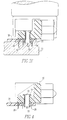
- Figs. 3a-3f are schematic illustrations of the connector, the printed wiring board and the connecting apparatus showing successive steps in the method of the present invention;
- Fig. 4 is a schematic illustration of the connector and printed wiring board showing the final connected assembly;
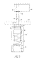
- Fig. 5 is a vertical cross sectional view of the locating projection element of the apparatus used in the method of the present invention;
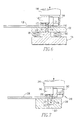
- Fig. 6 is a schematic end view of an alternate embodiment of the apparatus of the present invention; and
- Fig. 7 is a schematic end view of another alternate embodiment of the apparatus of the present invention.
-
- Referring to Figs. 1 and 2, a connector is shown generally at
numeral 10. This connector includes areceptacle 12, aguide pin 14, amounting bracket 16, apress block 18 and anend wall 20 positioned between the bracket and the press block. It will be understood that there is shown only one end of the connector and at the other end there will be a similarly positioned and essentially identical mounting bracket and guide pin. It will also be seen that the mounting bracket includes a hold downaperture 22 in which there is positioned an annular rivet which is also commonly referred to as aneyelet 24. Signal pins as at 26 and 28 extend downwardly from the press block. - Referring to Figs. 3a - 3f, a preferred embodiment of the method of the present invention is illustrated in greater detail. Referring particularly to Fig. 3a, it will be seen that in the first step of this method a
tooling plate 30 is provided which has an upwardly extending perpendicular locatingprojectile 32 along with deformation recesses as at 34 and 36. The functions of this projection and deformation recesses will be explained hereafter. A printedwiring board 38 having a pair of apertures as at 40 is positioned so that the apertures are engaged with the locating projections of the tooling plate and the printed wiring board abuts the tooling plate in side to side relation. Referring particularly to Fig. 3b, the connector is then superimposed over the printed wiring board and the tooling plate so that it's hold down apertures and the concentric eyelet are in vertical alignment with the locating projections at the tooling plate. In the next step of the method the eyelet is initially engaged with the locating projection as is shown in Fig. 3c. It will be noted from Fig. 3c that upon the initial engagement of the hold down aperture and the eyelet with the locating projection that the pins of the connectors are not yet engaged with a respective pin receiving aperture in the printed wiring board. Referring particularly to Fig. 3d, it will be seen that additional tooling is then provided by way of aneyelet support block 42 which is superimposed above the mounting bracket and in particular the hold down aperture and the eyelet. There is also a U-shapedchannel 44 which is positioned above the eyelet support block and the connector. Above the U-shaped channel there is also aram 46 which pushes downwardly on the connector. The action of this ram will result in the pins as at 26 and 28 engaging pin receiving apertures as at 48 and 50 in the printed wiring board. It will also be noted that there are pin receiving recesses as at 52 and 54 positioned immediately beneath each of the pin receiving apertures in the printed wiring board. At this stage of the method shown in Fig. 3d, however, the pins have not yet entered these pin receiving apertures. Referring particularly to Fig. 3e it will be seen that downward pressure by the ram continues in this method until the pins pass through the pin receiving apertures in the printed wiring board and enter the pin receiving recesses in the tooling plate. It will also be seen from Fig. 3e that the eyelet is pushed downwardly against deformation means at the base of the locating projection. This deformation means will preferably be an axially expanded lower section of the locating projection which will be disclosed hereafter in greater detail. Such downward axial pressure on the eyelet continues until the lower end of the eyelet will be crimped as at 55 as is shown in Fig. 3f. Upon the completion of this method, the tooling plate is removed to leave an assembly such as is shown in Fig. 4 wherein the eyelet engages the connector at its top and the printed wiring board at its bottom by means ofcrimp 55 to affix these elements together. - Referring to Fig. 5, the engagement of the locating projection, eyelet support block, the eyelet and the printed wiring board is shown in further detail. It will be seen that the eyelet support block has a
vertical bore 56 with arivet receiving recess 58 on its lower side. The locating projection has anupper nipple 60 and a lower axially expandeddeformation section 62. Outwardly from this deformation section there is anannular collar 64. Beneath the locating projection in the tooling plate there is also anaxial bore 66 in which there is aplug 68 which is at the upper end of aspring 70 which is attached at its lower end to aprojection spring base 72. Theeyelet 24 is positioned over the nipple of the locating projection and is retained at its lower end between that nipple and the annular collar and at its upper end in the recess of the eyelet support block. As downward axial pressure is applied to the eyelet its lower section is deformed outwardly by the lower flared deformation section of the locating projection. That lower portion is received in the deformation recesses so that a crimp is formed as at shown at numeral 55 in Fig. 4. While such downward axial pressure is applied to the eyelet,spring 70 is compressed in theaxial bore 66. After the lower end of the rivet has been crimped and the downward axial pressure is removed the spring expands to at least partially remove the printed wiring board from the locating projection. - Referring to Fig. 6, a second preferred embodiment of the method and apparatus of the present invention is illustrated. In this embodiment a connector shown generally at
numeral 110 and being essentially identical to those shown in Fig. 1 and 2 has been positioned with aeyelet 124 on anupper tooling plate 130 with a perpendicular locating projection as at 132 withdeformation recesses wiring board 138 is also engaged with the locating projections between the connector and the upper tooling plate in a manner similar to that described in connection with the first embodiment. Theupper tooling plate 130 is itself superimposed over abase plate 176 which has a medial raisedsection 178 from which the projection extends. Interposed between the upper tooling plate and the base plate arevertical springs springs - Referring to Fig. 7, a third preferred embodiment of the method and apparatus of the present invention is illustrated. In this embodiment a connector which is shown generally at
numeral 210 is essentially similar to the one described in conjunction with Figs. 1 and 2. This connector is mounted witheyelet 224 overtooling plate 230 which has a locatingprojection 232 which is positioned insideeyelet 224. In a manner similar to the embodiments described above, the apparatus of the embodiment includes aneyelet support block 242, a U-shaped channel 244 and aram 246. In this embodiment the connector is fixed to the printed wiring board in a manner as was described in the first two embodiments. After the eyelet has been moved downwardly to the deformation recesses 234 and 236, asolenoid 280 is automatically activated to move theprojection 236 upwardly. In this embodiment, an axially expandedsection 282 of the locating projection deforms the eyelet during the upward motion of the projection. The upward motion of the projection also causes the wiring board to at least partially disengage from theeyelet 224. - It will be appreciated that there has been described a method and apparatus for mounting a connector to a printed wiring board or other substrate which enables the eyelets or tubular rivets and the signal pins to be mounted in their respective apertures in one quick and efficient operation and which takes advantage of the need to mount those eyelets to easily align the signal pins with their pin receiving apertures.
- While the present invention has been described in connection with the preferred embodiments of the various figures, it is to be understood that other similar embodiments may be used or modifications and additions may be made to the described embodiment for performing the same function of the present invention.
- Therefore, the present invention should not be limited to any single embodiment, but rather construed in breadth and scope in accordance with the recitation of the appended claims.
Claims (15)
- An assembly for mounting an electrical connector (10; 110; 210) on a substrate (38; 138; 238), whereinthe connector (10; 110; 210) comprises a plurality of pins (26, 28) and at least one hold down means having an aperture (22; 122; 222) in which at least one fastening means (24; 124; 224) is disposed;the substrate (38; 138; 238) includes a plurality of pin receiving apertures (52, 54) for receiving the connector pins (26, 28) and at least one aperture (40) for receiving said fastening means (24; 124; 224); anda) the assembly includes a tooling plate (30; 130; 230) for receiving the substrate (38; 138; 238), and a projection (32; 132; 232) extending from said tooling plate or through said tooling plate (30; 130; 230) and adapted to be received in the fastening means receiving aperture (40) of the substrate (38; 138; 238) characterized in thatb) said projection is adapted to be received in the aperture (22; 122; 222) of the connector (10; 110; 210) for locating the connector (10; 110; 210) with respect to the substrate (38; 138; 238); andc) the projection (32; 132; 232) and/or the tooling plate (30; 130; 230) comprises deformation means (34, 36; 62; 134, 136; 234, 236) for deforming the fastening means (24; 124; 224) for causing the fastening means (24; 124; 224) to secure the connector (10; 110; 210) onto the substrate (38; 138; 238) as the pins (26, 28) of the connector (10; 110; 210) are inserted into the pin receiving apertures (52, 54) in the substrate (38; 138; 238).
- The assembly of claim 1, wherein said fastening means (24; 124; 224) is an eyelet.
- The assembly of claim 2, wherein an eyelet support block (42; 142; 242) and a ram (46; 146; 246) is provided for applying an axial force on said eyelet in the direction of the substrate (38; 138; 238).
- The assembly of any of claims 1 to 3, wherein at least one spring or a solenoid (70; 180, 182; 280) is provided for applying axial force on the projection (32; 132; 232) in the direction of the connector (10; 110; 210).
- The assembly of claim 4, wherein the projection (32) has an upper engagement nipple (60), and wherein beneath the projection (32) in the tooling plate there is an axial bore having an axial spring (70) and said axial spring (70) is the means for applying an axial force on the locating projection (32) in the direction of the connector (10).
- The assembly of any of claims 1 to 3, wherein the tooling plate (130) is superimposed over a base plate (176), said projection (132) extending from said base plate (176) and at least one spring (180, 182) is interposed between said tooling plate (130) and said base plate (176).
- A method of mounting an electrical connector (10; 110; 210) on a substrate (38; 138; 238), said connector (10; 110; 210) having a plurality of pins (26, 28) and at least one fastening means (24; 124; 224), comprising the steps of:a) positioning a substrate (38; 138; 238) having pin receiving means, comprising a plurality of pin receiving apertures (52; 54), and at least one fastening means receiving aperture (40) in the substrate, adjacent to a tooling plate (30; 130; 230), wherein a projection (32; 132; 232) is extending from or through said tooling plate (30; 130; 230), such that the projection (32; 132; 232) is aligned with the aperture (40) on the substrate (38; 138; 238);b) positioning the connector (10; 110; 210) such that the fastening means (24; 124; 224)is aligned with said projection (32; 132; 232);
characterized in that:c) said connector (10; 110; 210) further comprises hold down means with an aperture (22; 122; 222) having said fastening means (24; 124; 224) disposed therein, and said projection (32; 132; 232) and or, said tooling plate (30; 130; 230) comprises a means (34, 36; 62; 134, 136; 234, 236), for deforming the fastening means (24; 124; 224), wherein said method further comprisesd) further engaging said fastening means (24; 124; 224) with the projection (32; 132; 232) until the connector pins (26, 28) engage the pin receiving means in the substrate; ande) causing said fastening means (24; 124; 224) to secure the connector (10; 110; 210) onto the substrate (38; 138; 238) by engaging the fastening means (24; 124; 224) by said deformation, as the pins (26; 28) of the connector (10; 110; 210) are inserted into the pin-receiving apertures (53; 54) in the substrate (38; 138; 238). - The method of claim 7, wherein the fastening means (24; 124; 224) is an eyelet.
- The method of claim 8, wherein said deformation means comprising a radially expanded section of the projection (32; 132; 232), and wherein in step e) an axial force is applied to the eyelet against said radially expanded section of the projection (32; 132; 232).
- The method of claim 9, wherein in step b) the substrate aperture (40) for receiving said fastening means and the concentric eyelet are aligned in axial relation with the projection (32; 132; 232).
- The method of any of claims 9 to 10, wherein in step d) said eyelet is deformed outwardly to engage the substrate (38; 138; 238).
- The method of any of claims 7 to 11, wherein the substrate has two opposed ends and there is a substrate aperture position towards each of said ends.
- The method of any of claims 7 to 12, wherein the eyelet circumferentially abuts said fastening means receiving aperture (40).
- The method of any of claims 7 to 13, wherein the locating projection (32) has an upper engagement nipple (60), and wherein beneath the projection (32) in the tooling plate there is an axial bore having an axial spring (70) and said axial spring (70) is the means for applying an axial force on the locating projection (32) in the direction of the connector (10), and the axial force applied to the locating projection results from an expansion of said axial spring after the completion of step c).
- The method of any of claims 7 to 13, wherein the tooling plate (130) is superimposed over a base plate (176), said projection (132) extending from said base plate (176), and at least one spring (180; 182) is interposed between said tooling plate (130) and said base plate (176) and said spring is compressed during step c), and the axial force applied to the tooling plate results from the expansion of said spring (180, 182).
Applications Claiming Priority (2)
| Application Number | Priority Date | Filing Date | Title |
|---|---|---|---|
| US08/443,789 US5815917A (en) | 1995-05-17 | 1995-05-17 | Method and apparatus for mounting an electrical connector on a printed wiring board |
| US443789 | 1995-05-18 |
Publications (3)
| Publication Number | Publication Date |
|---|---|
| EP0743704A2 EP0743704A2 (en) | 1996-11-20 |
| EP0743704A3 EP0743704A3 (en) | 1997-07-23 |
| EP0743704B1 true EP0743704B1 (en) | 2001-10-31 |
Family
ID=23762214
Family Applications (1)
| Application Number | Title | Priority Date | Filing Date |
|---|---|---|---|
| EP96107767A Expired - Lifetime EP0743704B1 (en) | 1995-05-17 | 1996-05-15 | Method and apparatus for mounting an electrical connector on a printed wiring board |
Country Status (3)
| Country | Link |
|---|---|
| US (3) | US5815917A (en) |
| EP (1) | EP0743704B1 (en) |
| DE (1) | DE69616419D1 (en) |
Families Citing this family (12)
| Publication number | Priority date | Publication date | Assignee | Title |
|---|---|---|---|---|
| US5815917A (en) * | 1995-05-17 | 1998-10-06 | Berg Technology, Inc. | Method and apparatus for mounting an electrical connector on a printed wiring board |
| US6231403B1 (en) * | 1997-03-07 | 2001-05-15 | Berg Technology, Inc. | Apparatus for assembling an electrical connector and method of use |
| TW354199U (en) * | 1997-12-31 | 1999-03-01 | Hon Hai Prec Ind Co Ltd | Press-in aid for electric connector |
| US6507998B1 (en) * | 1998-03-05 | 2003-01-21 | Tektronix, Inc. | Method of mounting an electrical receptacle on a substrate |
| BE1011920A3 (en) * | 1998-05-15 | 2000-03-07 | Framatome Connectors Belgium | Method and device for the positioning of a plate with printed circuits in a press. |
| US6233805B1 (en) | 1999-09-15 | 2001-05-22 | Lucent Technologiesinc. | Arrangement for manipulating an pin in an electrical assembly including a reciprocating engaging member |
| US6581274B1 (en) | 2000-05-24 | 2003-06-24 | Trans Tron Ltd., Inc. | Apparatus for configuring and inserting component leads into printed-circuit boards |
| US7678465B2 (en) * | 2002-07-24 | 2010-03-16 | Applied Thin Films, Inc. | Aluminum phosphate compounds, compositions, materials and related metal coatings |
| WO2004016548A2 (en) * | 2002-08-14 | 2004-02-26 | Applied Thin Films, Inc. | Aluminum phosphate compounds, compositions, materials and related composites. |
| US9055879B2 (en) * | 2013-06-14 | 2015-06-16 | Suunto Oy | Device and method for assembling an electronic device and a flexible element for facilitating assembly of electronic components |
| CN116746290A (en) | 2021-05-25 | 2023-09-12 | 三星电子株式会社 | Display device and manufacturing method thereof |
| KR102940769B1 (en) * | 2021-05-25 | 2026-03-19 | 삼성전자주식회사 | Display apparatus amd manufacturing method thereof |
Family Cites Families (20)
| Publication number | Priority date | Publication date | Assignee | Title |
|---|---|---|---|---|
| US2856593A (en) * | 1954-06-21 | 1958-10-14 | United Shoe Machinery Corp | Connector joint and method of making same |
| GB1196457A (en) * | 1967-07-06 | 1970-06-24 | Konstantin Alexee Konstantinov | A Device for Upsetting Tubular Rivets |
| US3924325A (en) * | 1974-07-02 | 1975-12-09 | Molex Inc | Method and apparatus for mounting terminal pins from a single side of a double sided terminal board |
| US3980367A (en) | 1975-03-19 | 1976-09-14 | Sealectro Corporation | Electrical connector for joining conductors attached to printed circuit boards |
| US4287667A (en) * | 1978-02-14 | 1981-09-08 | Alps Electric Co., Ltd. | Method of mounting an electrical component |
| US4328613A (en) * | 1980-03-27 | 1982-05-11 | Bell Telephone Laboratories, Incorporated | Connector lead insertion method |
| US4812130A (en) * | 1985-06-27 | 1989-03-14 | Rca Licensing Corp. | Printed circuit board with mounted terminal |
| US4717219A (en) | 1986-06-19 | 1988-01-05 | Amp Incorporated | Electrical connector and assembly eyelets |
| US4719695A (en) * | 1986-08-06 | 1988-01-19 | Rca Corporation | Printed circuit board support fixture for connector wire wrap pins |
| US4721470A (en) * | 1987-04-13 | 1988-01-26 | E. I. Du Pont De Nemours And Company | Keys for electrical connectors |
| US4884336A (en) * | 1987-09-22 | 1989-12-05 | Amp Incorporated | Method and apparatus for mounting electrical connectors to printed circuit boards |
| FR2646312B1 (en) * | 1989-04-21 | 1991-06-07 | Cit Alcatel | COMPONENT SUPPORT FOR FIXING THE COMPONENT TO A PRINTED CIRCUIT, AND METHOD FOR PRODUCING AND USING SUCH A SUPPORT |
| US4953061A (en) * | 1989-07-03 | 1990-08-28 | Zenith Electronics Corporation | Holder for printed circuit board components |
| US5066237A (en) | 1990-10-22 | 1991-11-19 | Itt Corporation | Connector press fit eyelet |
| US5277618A (en) * | 1991-05-02 | 1994-01-11 | E. I. Du Pont Nemours And Company | Connector having fixing means for mounting on a substrate |
| US5108308A (en) * | 1991-05-31 | 1992-04-28 | Amp Incorporated | Pylon actuated locking eyelet |
| US5230639A (en) | 1992-06-12 | 1993-07-27 | Amp Incorporated | Top activated eyelet and tool for use therewith |
| CA2104438C (en) * | 1992-11-02 | 1996-07-02 | James Stephen Chapman | Method and apparatus for mounting connectors |
| US5815917A (en) * | 1995-05-17 | 1998-10-06 | Berg Technology, Inc. | Method and apparatus for mounting an electrical connector on a printed wiring board |
| US5762523A (en) | 1996-03-27 | 1998-06-09 | Berg Technology, Inc. | Device for mounting an electrical connector on a printed circuit board |
-
1995
- 1995-05-17 US US08/443,789 patent/US5815917A/en not_active Expired - Fee Related
-
1996
- 1996-05-15 DE DE69616419T patent/DE69616419D1/en not_active Expired - Lifetime
- 1996-05-15 EP EP96107767A patent/EP0743704B1/en not_active Expired - Lifetime
-
1998
- 1998-01-26 US US09/013,491 patent/US6038762A/en not_active Expired - Fee Related
-
1999
- 1999-11-01 US US09/431,397 patent/US6230392B1/en not_active Expired - Fee Related
Also Published As
| Publication number | Publication date |
|---|---|
| US6230392B1 (en) | 2001-05-15 |
| EP0743704A3 (en) | 1997-07-23 |
| US5815917A (en) | 1998-10-06 |
| DE69616419D1 (en) | 2001-12-06 |
| US6038762A (en) | 2000-03-21 |
| EP0743704A2 (en) | 1996-11-20 |
Similar Documents
| Publication | Publication Date | Title |
|---|---|---|
| US5815917A (en) | Method and apparatus for mounting an electrical connector on a printed wiring board | |
| EP0250097B1 (en) | Electrical connector for easy assembly onto a circuit board and eyelets therefor | |
| EP0516023B1 (en) | Pylon actuated locking eyelet | |
| US5476350A (en) | Slotted push-in rivet and method of riveting | |
| US5603636A (en) | Attachment of terminal contacts to coaxial cable end and cable connector having terminal contacts | |
| US7044751B2 (en) | Construction for connecting a circuit board and an electrical part, a brake oil pressure control unit | |
| US5039139A (en) | Tube spring steel tab lock coupling connector and method for connecting telescoping tubes | |
| EP1107390A3 (en) | A method for mounting a connector on a panel and a connector assembly | |
| US20040235322A1 (en) | Screwless circuit board attachment | |
| US7382630B2 (en) | Board-mounting device | |
| US5188536A (en) | Space-saving insulation displacement type interconnect device for electrically coupling a ribbon connector to a printed circuit board | |
| US4769896A (en) | Method of forming a metal-to-plastic joint | |
| US7874776B1 (en) | Clinch for a circuit card ejector | |
| US5082407A (en) | Fastener retainer | |
| JP3366944B2 (en) | O-ring assembly device | |
| US6139362A (en) | Fastener for connecting an electrical device to a substrate | |
| US20080102663A1 (en) | Board-mounted type connector to which a shield plate is attached | |
| EP0647990A1 (en) | Electrical connector hold down anchor apparatus | |
| US5287617A (en) | Apparatus for extracting an integrated circuit package installed in a socket on a circuit board | |
| US6655969B2 (en) | Contact elements | |
| US5697141A (en) | Method of securing members together | |
| US6012215A (en) | Apparatus and method for inserting multiple self clinching fasteners | |
| US6443752B1 (en) | Terminal | |
| EP0833551B1 (en) | Socket for connecting an integrated circuit to a printed wiring board | |
| JP3288458B2 (en) | Method and apparatus for manufacturing transmission retainer assembly |
Legal Events
| Date | Code | Title | Description |
|---|---|---|---|
| PUAI | Public reference made under article 153(3) epc to a published international application that has entered the european phase |
Free format text: ORIGINAL CODE: 0009012 |
|
| AK | Designated contracting states |
Kind code of ref document: A2 Designated state(s): DE FR GB |
|
| PUAL | Search report despatched |
Free format text: ORIGINAL CODE: 0009013 |
|
| RHK1 | Main classification (correction) |
Ipc: H01R 23/70 |
|
| AK | Designated contracting states |
Kind code of ref document: A3 Designated state(s): DE FR GB |
|
| 17P | Request for examination filed |
Effective date: 19971024 |
|
| 17Q | First examination report despatched |
Effective date: 19990715 |
|
| GRAG | Despatch of communication of intention to grant |
Free format text: ORIGINAL CODE: EPIDOS AGRA |
|
| GRAG | Despatch of communication of intention to grant |
Free format text: ORIGINAL CODE: EPIDOS AGRA |
|
| GRAH | Despatch of communication of intention to grant a patent |
Free format text: ORIGINAL CODE: EPIDOS IGRA |
|
| GRAH | Despatch of communication of intention to grant a patent |
Free format text: ORIGINAL CODE: EPIDOS IGRA |
|
| GRAA | (expected) grant |
Free format text: ORIGINAL CODE: 0009210 |
|
| RIC1 | Information provided on ipc code assigned before grant |
Free format text: 7H 01R 12/20 A, 7H 01R 43/20 B |
|
| AK | Designated contracting states |
Kind code of ref document: B1 Designated state(s): DE FR GB |
|
| REF | Corresponds to: |
Ref document number: 69616419 Country of ref document: DE Date of ref document: 20011206 |
|
| REG | Reference to a national code |
Ref country code: GB Ref legal event code: IF02 |
|
| PG25 | Lapsed in a contracting state [announced via postgrant information from national office to epo] |
Ref country code: DE Free format text: LAPSE BECAUSE OF FAILURE TO SUBMIT A TRANSLATION OF THE DESCRIPTION OR TO PAY THE FEE WITHIN THE PRESCRIBED TIME-LIMIT Effective date: 20020201 |
|
| ET | Fr: translation filed | ||
| PG25 | Lapsed in a contracting state [announced via postgrant information from national office to epo] |
Ref country code: GB Free format text: LAPSE BECAUSE OF NON-PAYMENT OF DUE FEES Effective date: 20020515 |
|
| PLBE | No opposition filed within time limit |
Free format text: ORIGINAL CODE: 0009261 |
|
| STAA | Information on the status of an ep patent application or granted ep patent |
Free format text: STATUS: NO OPPOSITION FILED WITHIN TIME LIMIT |
|
| 26N | No opposition filed | ||
| GBPC | Gb: european patent ceased through non-payment of renewal fee |
Effective date: 20020515 |
|
| PG25 | Lapsed in a contracting state [announced via postgrant information from national office to epo] |
Ref country code: FR Free format text: LAPSE BECAUSE OF NON-PAYMENT OF DUE FEES Effective date: 20030131 |
|
| REG | Reference to a national code |
Ref country code: FR Ref legal event code: ST |