EP0742756B1 - Method and apparatus for cleaning a roller surface - Google Patents
Method and apparatus for cleaning a roller surface Download PDFInfo
- Publication number
- EP0742756B1 EP0742756B1 EP94920416A EP94920416A EP0742756B1 EP 0742756 B1 EP0742756 B1 EP 0742756B1 EP 94920416 A EP94920416 A EP 94920416A EP 94920416 A EP94920416 A EP 94920416A EP 0742756 B1 EP0742756 B1 EP 0742756B1
- Authority
- EP
- European Patent Office
- Prior art keywords
- cylinder
- cleaning
- orifice
- cylinder surface
- pipe
- Prior art date
- Legal status (The legal status is an assumption and is not a legal conclusion. Google has not performed a legal analysis and makes no representation as to the accuracy of the status listed.)
- Expired - Lifetime
Links
- 238000004140 cleaning Methods 0.000 title claims abstract description 86
- 238000000034 method Methods 0.000 title claims abstract description 42
- 238000007639 printing Methods 0.000 claims abstract description 36
- 239000002245 particle Substances 0.000 claims abstract description 24
- 239000012530 fluid Substances 0.000 claims abstract description 21
- 239000007788 liquid Substances 0.000 claims abstract description 18
- 239000000463 material Substances 0.000 claims abstract description 10
- 239000000428 dust Substances 0.000 claims abstract description 5
- 239000007787 solid Substances 0.000 claims description 7
- 239000002184 metal Substances 0.000 claims description 5
- 239000000123 paper Substances 0.000 claims description 5
- 239000002985 plastic film Substances 0.000 claims description 5
- 229920006255 plastic film Polymers 0.000 claims description 5
- 239000000203 mixture Substances 0.000 claims description 3
- 230000008569 process Effects 0.000 abstract description 14
- 238000002604 ultrasonography Methods 0.000 abstract description 9
- 239000000835 fiber Substances 0.000 abstract 1
- 239000002699 waste material Substances 0.000 description 5
- 230000000694 effects Effects 0.000 description 3
- 239000003595 mist Substances 0.000 description 3
- 239000012535 impurity Substances 0.000 description 2
- 230000009467 reduction Effects 0.000 description 2
- 239000003570 air Substances 0.000 description 1
- 230000005540 biological transmission Effects 0.000 description 1
- 230000008859 change Effects 0.000 description 1
- 238000000151 deposition Methods 0.000 description 1
- 238000005108 dry cleaning Methods 0.000 description 1
- 230000005611 electricity Effects 0.000 description 1
- 238000007647 flexography Methods 0.000 description 1
- 239000011796 hollow space material Substances 0.000 description 1
- 230000000873 masking effect Effects 0.000 description 1
- 230000007246 mechanism Effects 0.000 description 1
- 238000003825 pressing Methods 0.000 description 1
- 230000003068 static effect Effects 0.000 description 1
- 230000007306 turnover Effects 0.000 description 1
Images


Classifications
-
- B—PERFORMING OPERATIONS; TRANSPORTING
- B41—PRINTING; LINING MACHINES; TYPEWRITERS; STAMPS
- B41F—PRINTING MACHINES OR PRESSES
- B41F35/00—Cleaning arrangements or devices
- B41F35/02—Cleaning arrangements or devices for forme cylinders
Definitions
- the present invention relates to a method for automatic cleaning of a cylinder, especially a cylinder of a printing machine, in which the cylinder is provided with plates and used for printing on a print carrier made of e.g. paper, plastic film, or metal film, and in which the cylinders become smudged, during printing, with printing ink, particles detached from said print carrier such as dust or fibres, and other foreign objects, wherein an area of the cylinder surface is cleaned by exposing said area to a pressurized flow of fluid so that the foreign objects inside the area on the cylinder surface are detached, and wherein said area is exposed to a vacuum to remove said detached foreign objects and any other material originating from said flow of fluid.
- a print carrier made of e.g. paper, plastic film, or metal film
- So-called flexographic printing on a print carrier of paper, plastic film or metal film uses a system consisting of a first cylinder, around which a web of the print carrier runs, a second cylinder performing the actual printing and being provided with plates for this purpose, and a third cylinder transmitting ink to the second cylinder.
- EP-0,369,565 describes a cleaner for automatic cleaning of a cylinder by pressing or otherwise discarding impuritues from the surface of the cylinder.
- the cylinder cleaner comprises a brush extending along the total length of the cylinder or, in another embodiment, a bar for applying pressurized air or ultrasound.
- the cleaning takes place by rotating or displacing the brush along the entire length of the cylinder or by applying pressurized air or ultrasound along the entire length of the bar.
- This cleaner has the great inconvenience that the efficiency of the cleaning is strongly reduced. Firstly, cleaning by using a brush quickly results in the brush being worn up together with the surface of the cylinder being worn.
- cleaning by using pressurized air or ultrasound being applied to the total length of the cylinder has the effect that the efficiency of the cleaning is not the same over the total length of the cylinder.
- the pressurized air or the ultrasound is applied at one end of the bar and, therefore, the efficiency of the cleaning will be highest at the first end of the bar and lowest at a second end of the bar opposite the end at which the pressurized air or the ultrasound is applied.
- JP 63-4947 describes a further apparatus for cleaning the surface of a roller in a typographic rotary press.
- This apparatus comprises a jet nozzle for supplying a jet of pressurized air and also a vacuum duct for evacuating the impurities detached from the surface of the roller.
- the jet nozzle is located inside in the vacuum duct.
- the cylinder surface is constituted by adjacent areas lengthwise and crosswise on the cylinder surface provided by such area extending over a minor part of the circumference of said cylinder and a minor part of the length of said cylinder, and that said adjacent areas of said cylinder surface are cleaned successively, wherein the pressurized fluid is provided by mixing pressurized air and a liquid in a mixing chamber, and that the so-formed mixture is led to the print plate through nozzles being connected with the mixing chamber.
- the area around the length of the cylinder is extended as compared to using only one nozzle. Thereby the amount of time used for cleaning the surface is strongly reduced. A larger area, although still just a small area of the surface, is cleaned and accordingly, an orifice with a cleaning can be displaced along the length of the roller at a much higher speed. As mentioned before, it is very important to reduce the amount of time used during the cleaning process.
- the method is advantageous in that cleaning is performed automatically and preferably while the printing process is running.
- Such media could be an ultrasound field or various kinds of solid matter particles may be added to the fluid media constituting a fluidized medium.
- the particles will normally have to be removed from the surface. This is accomplished in that, after the particles have been detached from the surface, the cylinder is exposed to a vacuum sucking the particles off the surface. Any other material originating from the cleaning process, e.g. solid matter particles which have been used in the cleaning process, may be sucked off at the same time. It will also be possible to load the particles that are to be detached, or have become detached, with static electricity and subsequently to use an electric voltage field to assist in the removal of the particles from the cylinder surface.
- the cleaning medium should preferably be directed in an inclined angle in relation to the tangent of the cylinder surface. This will ensure that particles depositing on the sides of the plates are removed as well.
- the inclined flow will attack both the cylinder surface and the cylinder sides in an inclined angle, not parallel or perpendicular.
- the method is further advantageous in that no damage is done to the plates during the cleaning process.
- the method is suitable for cleaning printing cylinders in flexography which printing process uses cylinders with printing plates.
- the method may be used for many types of rollers and cylinders, not just printing cylinders.
- Apparatuses for use by the method according to the present invention may be designed in many different ways. Two types of apparatuses are disclosed according to the present invention.
- One apparatus comprises mobile cleaning members in the shape of a cleaning head being slid over the cylinder surface whereby successive cleaning of the surface takes place.
- the other apparatus comprises fixed cleaning members provided with an internal device likewise conducting a successive surface cleaning. It is a common feature that an antechamber is provided for effecting a mixing of liquid and a pressurized air.
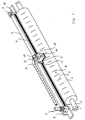
- Fig. 1 illustrates part of a machine for flexographic printing, which machine is provided with an apparatus according to the invention.
- the machine comprises a cylinder 1 with plates 2.
- the cylinder 1 rotates around a shaft 3.
- the apparatus comprises a boom 4 on which a cleaning head 5 is conveyed. Conveyance is effected by means of a band 6 driven by a motor 7 such as a pneumatic motor, a hydraulic motor or other type of motor.
- the motor 7 is located at one end 8 of the boom 4, and the band 6 is led over a pulley 9 in the other end 10 of said boom.
- the cleaning head 5 is fixed to the band 6 by means of a slide 11 which is movable relative to the boom 4.
- the cleaning head 5 is mounted on said slide, and the cleaning head is provided with three tubes 12, 13, 14 connected thereto.
- the thin tubes 11, 12 are used for conveying compressed air from an external pressure source, and liquid is fed to the cleaning head 5 through an antechamber 15 wherein mixing of compressed air and liquid takes place.
- the thick tube 14 is used, during exposure of the cylinder surface 16 to a vacuum from an external vacuum source, to remove loosened particles and other material from the cylinder surface.
- the cleaning head 5 is provided with small nozzles through which the compressed air and the liquid, possibly containing fluidized particles of solid matter, are conveyed to the surface.
- the direction of cylinder rotation r will preferably be oriented in such a manner that the surface areas to be cleaned are led towards the cleaning head front 17, which is opposite the side of the cleaning head 5 mounted on the slide 11.
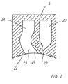
- Fig. 2 illustrates a cross-section through a cleaning head 5.
- the cleaning head 5 comprises two chambers 20, 21, the first chamber 20 of which is connected to the antechamber 15 (see fig. 1), and the second chamber 21 is connected to the thick tube for vacuum application.
- the underside 22 of the cleaning head 5 constitutes a segment of a circle and when mounted it is immediately adjacent the cylinder surface.
- An orifice 23 of the first chamber is inclined in relation to the periphery of the cleaning head underside 22. This ensures improved cleaning of the cylinder surface 16.
- the orifice 23 of the first chamber will be provided with screens which are provided with nozzles or slots, which may have different sizes and different directions (see figs. 3A-3C).
- the cleaning head is provided with a recess 24 before the orifice 23 of the first chamber 20.
- the second chamber 21 is provided with an orifice 25 having an extension that ensures that all material from the cylinder surface 16 will be removed.
- Figs. 3A, 3B and 3C illustrate different embodiments of screens 30A, 30B, 30C.
- Fig. 3A shows a screen 30A provided with several small holes 31 the longitudinal axis l A of which is directed in a 90° angle ⁇ A in relation to the plane p A of the screen 30A.
- the screen 30A is further provided with bolt holes 32 so that the screen may be affixed to the cleaning head 5.
- Fig. 3B shows a second screen 30B provided with a slot 33 instead of holes. The slot is also inclined in a 90° angle ⁇ B in relation to the plane p B of the screen 30B.
- Fig. 3C shows an additional screen 30C. likewise provided with a slot 34.
- the slot 34 of this embodiment is directed in a 75° angle ⁇ C in relation to the plane p C of the screen.
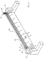
- Fig. 4 illustrates part of a machine provided with a second embodiment of an apparatus according to the invention for use by the method according to the invention.
- said machine is a machine for flexographic printing.
- the machine comprises a cylinder 1 provided with plates 2, said cylinder being supported by a shaft 3.
- a pipe member 40 Positioned alongside the cylinder is a pipe member 40.
- the pipe member 40 comprises two pipes, a nozzle pipe 41 and a suction pipe 42, respectively, and a jacket 43.
- the pipes 41, 42 are supported in both ends, a first end 44 and a second end 45, respectively.
- the second end 45 of either pipe is open and connected with compressed air and liquid pipes 46, 47 and, respectively, a suction pipe 48 for the application of a vacuum from an external vacuum source to the suction pipe 42.
- Fig. 5 shows that the first end 44 of either pipe 41, 42 is closed and that the pipes are interconnected by means of a gear comprising two gear wheels 49, 50 so that the pipes are rotatable around the longitudinal axes at a given mutual speed of rotation.
- a motor 51 such as a pneumatic motor, a hydraulic motor or other type of motor, is connected to the suction pipe 42.
- the motor drives the suction pipe 42, which drives the nozzle pipe 41 via the gear transmission with the latter.
- the motor 51 and the gear are sheltered by a box 52.
- the figure illustrates the first end 44 of the pipe member 40 seen from a side 56 facing the cylinder. On this side, the jacket 43 of the pipe member 40 is provided with nozzles 53 and a slot 54.
- the nozzles 53 are in connection with the outside surface of the nozzle pipe 41, whereas the slot 54 is in connection with the outside surface of the suction pipe 42.
- Fig. 6 illustrates the nozzle pipe 41 or, alternatively, the suction pipe 42.
- a preferred embodiment of either one of the nozzle pipe and the suction pipe is provided with a slot 55 spiraling along the length of either pipe.
- the slot 55 extends in such a manner that the spiral completes exactly one turn over the extension of the slot from one end of either pipe to the other.
- one or both of the pipes are just provided with a rectilinear slot. The function of the two pipes will be described below.
- Fig. 7 is a cross-section illustrating the position of the nozzle pipe 41 and the suction pipe 42 relative to each other inside the pipe member 40.
- the pipe member comprises, as mentioned, a jacket 43 enclosing the two pipes which are thus positioned in two cavities in the jacket.
- the nozzle and suction pipes may be enclosed in the hollow space formed by the inside of additional pipes having an inside diameter corresponding to the outside diameter of the nozzle pipe and the suction pipe, respectively. In that case, these additional pipes would be provided with nozzles 53 and a slot 54 corresponding to the ones provided in the jacket.
- the nozzles 53 and the slot 54 in the jacket 43 extend from one side 56 of the pipe member 40, facing the cylinder 1, to the nozzle pipe 41 and the suction pipe 42, respectively.
- the nozzle pipe 41 will be connected to a source of compressed air and possibly also a source of liquid which may contain fluidized particles of solid matter.
- the nozzle pipe 41 may be connected to an ultrasound source which effects a cleaning of the cylinder surface 16 by means of the liquid.
- the cleaning medium is conveyed out through this part of the screw-shaped slot and on through the nozzles 53, and due to the uniform pressure in the pipe, the cleaning effect of the cleaning medium will be equal throughout the extension of the jacket 43. Contrarily, if the cleaning medium were conveyed out through all nozzles 53 at the same time, a pressure reduction would soon arise along the nozzle pipe, the lowest pressure occurring opposite the end where the pressure is conveyed to the pipe.
- the nozzle pipe 41 of the present invention is thus subject to constant feeding of cleaning medium but the medium is only conveyed to a small area of the cylinder surface corresponding to the location along the extension of the nozzles 53 where the slot of the nozzle pipe overlaps the nozzles. During the rotation of the nozzle pipe, alternating parts of the slot will successively overlap the nozzles.
- the suction pipe 42 Its function is structured in such a manner that cleaning is only effected on minor areas of the cylinder surface, said areas being exposed successively to a vacuum whereby the whole surface of the cylinder is cleaned.
- the suction pipe 42 is in a constant vacuum from an external vacuum source. The area of the cylinder surface being exposed to the vacuum will be the area positioned adjacent the location where part of the screw-shaped slot 55 in the suction pipe 42 overlaps the rectilinear slot in the jacket 43.
- the suction pipe 42 of the present embodiment is thus able to suck off particles successively from adjacent areas of the cylinder surface due to the fact that the overlap of the screw-shaped slot 55 in the suction pipe 42 and the rectilinear slot 54 in the jacket 43 is transposed along the pipe member 40 during the rotation of the suction pipe.
- the slot 54 in the jacket 43 of a preferred embodiment is designed so as to extend over a shorter distance than the slot 55 in the suction pipe 42.
- the mutual gearing between the nozzle pipe and the suction pipe is designed in such a manner that the flow of fluid from the nozzle pipe and the vacuum from the suction pipe are turned off simultaneously.
Landscapes
- Inking, Control Or Cleaning Of Printing Machines (AREA)
- Rolls And Other Rotary Bodies (AREA)
- Electrical Discharge Machining, Electrochemical Machining, And Combined Machining (AREA)
- Cleaning In General (AREA)
- Pinball Game Machines (AREA)
Abstract
Description
- The present invention relates to a method for automatic cleaning of a cylinder, especially a cylinder of a printing machine, in which the cylinder is provided with plates and used for printing on a print carrier made of e.g. paper, plastic film, or metal film, and in which the cylinders become smudged, during printing, with printing ink, particles detached from said print carrier such as dust or fibres, and other foreign objects, wherein an area of the cylinder surface is cleaned by exposing said area to a pressurized flow of fluid so that the foreign objects inside the area on the cylinder surface are detached, and wherein said area is exposed to a vacuum to remove said detached foreign objects and any other material originating from said flow of fluid.
- So-called flexographic printing on a print carrier of paper, plastic film or metal film uses a system consisting of a first cylinder, around which a web of the print carrier runs, a second cylinder performing the actual printing and being provided with plates for this purpose, and a third cylinder transmitting ink to the second cylinder.
- When the printing process has continued for a certain time, there will normally arise problems with the printing quality. This is because the second cylinder, the printing cylinder, has become smudged with dust, fibres or other particles from the web of paper, plastic film or metal film. When this occurs, it is necessary to halt the printing process, displace the cylinder from its bearing and then manually brush or wash impurities off the second cylinder. This is a serious inconvenience since it means that the stoppage periods may amount to as much as 30 per cent of the total time in which the machine is in use. This means that the operation time in which printing takes place may risk being reduced to 70 per cent of the time in which the machine is in use. Out of those 30 per cent of time in which the machine is halted, up to 90 per cent is due to cleaning the printing cylinder. Furthermore, the waste of paper, plastic film or metal film is substantial because there is a certain running-in period after a stoppage and the web of paper or film being printed during this period does not have a sufficient quality and must be discarded.
- EP-0,369,565 describes a cleaner for automatic cleaning of a cylinder by pressing or otherwise discarding impuritues from the surface of the cylinder. The cylinder cleaner comprises a brush extending along the total length of the cylinder or, in another embodiment, a bar for applying pressurized air or ultrasound. The cleaning takes place by rotating or displacing the brush along the entire length of the cylinder or by applying pressurized air or ultrasound along the entire length of the bar. This cleaner, however, has the great inconvenience that the efficiency of the cleaning is strongly reduced. Firstly, cleaning by using a brush quickly results in the brush being worn up together with the surface of the cylinder being worn. Secondly, cleaning by using pressurized air or ultrasound being applied to the total length of the cylinder has the effect that the efficiency of the cleaning is not the same over the total length of the cylinder. The pressurized air or the ultrasound is applied at one end of the bar and, therefore, the efficiency of the cleaning will be highest at the first end of the bar and lowest at a second end of the bar opposite the end at which the pressurized air or the ultrasound is applied.
- JP 63-4947 describes a further apparatus for cleaning the surface of a roller in a typographic rotary press. This apparatus comprises a jet nozzle for supplying a jet of pressurized air and also a vacuum duct for evacuating the impurities detached from the surface of the roller. Like in the previous publication, the jet nozzle is located inside in the vacuum duct. Although using pressurized air, this apparatus has the great inconvenience of having only one jet nozzle for supplying the pressurized air. The jet nozzle has to be displaced along the length of the roller very slowly in order to ensure that the whole surface of the roller is cleaned. Therefore, the cleaning process when using the apparatus described in that publication will take a very large amount of time.
- Thus, it is the object of the present invention to provide a method which may be carried out automatically, and in which the above-mentioned inconveniences, such as unsuitable cleaning media and very long time for carrying out the cleaning process, are avoided.
- This object is achieved by a method characterized in that the cylinder surface is constituted by adjacent areas lengthwise and crosswise on the cylinder surface provided by such area extending over a minor part of the circumference of said cylinder and a minor part of the length of said cylinder, and that said adjacent areas of said cylinder surface are cleaned successively, wherein the pressurized fluid is provided by mixing pressurized air and a liquid in a mixing chamber, and that the so-formed mixture is led to the print plate through nozzles being connected with the mixing chamber.
- In addition, apparatuses for use by the method will be disclosed.
- By the method according to the present invention it is now possible, during operation, to clean a cylinder, particularly a flexographic printing cylinder. In this manner one avoids the substantial time waste previously associated with cleaning the cylinder. Reducing the time waste, one also reduces the waste of material accordingly as cleaning is accomplished during ordinary operational conditions. If cylinder cleaning is carried out before it is so smudged as to deteriorate the printing quality, there will be neither material nor time waste during cleaning.
- By using several nozzles or a slot, the area around the length of the cylinder is extended as compared to using only one nozzle. Thereby the amount of time used for cleaning the surface is strongly reduced. A larger area, although still just a small area of the surface, is cleaned and accordingly, an orifice with a cleaning can be displaced along the length of the roller at a much higher speed. As mentioned before, it is very important to reduce the amount of time used during the cleaning process.
- The method is advantageous in that cleaning is performed automatically and preferably while the printing process is running.
- As pressurized air containing the admixed liquid is used for detaching the particles from the printing cylinder it is possible to obtain a secure and effective cleaning even if ink and dust stick very hard to the printing cylinder. Surprisingly, and in contradiction to the expectation for the skilled in this art it has shown that is is possible to use such mixture in a cleaning process while the printing process is running. It has shown that the cleaning will not harm the quality of the printing even though it is not a dry cleaning as explained in the JP 63-4947. It is believed that the reason for the effective cleaning is that a mist is produced, which mist is led to the printing cylinder. Such mist may be sucked away very effective in comparison with a liquid even if rather limited level of vacuum is used.
- For various reasons, however, it may be advantageous to add other media, e.g. depending on the ink used for printing, the material being printed on, the kind of particles to detach from the cylinder, or the speed at which the printing process is operating. Such media could be an ultrasound field or various kinds of solid matter particles may be added to the fluid media constituting a fluidized medium.
- Having become detached from the cylinder surface, the particles will normally have to be removed from the surface. This is accomplished in that, after the particles have been detached from the surface, the cylinder is exposed to a vacuum sucking the particles off the surface. Any other material originating from the cleaning process, e.g. solid matter particles which have been used in the cleaning process, may be sucked off at the same time. It will also be possible to load the particles that are to be detached, or have become detached, with static electricity and subsequently to use an electric voltage field to assist in the removal of the particles from the cylinder surface.
- In order to ensure that the cylinder with the plates is cleaned both on and between the plates, the cleaning medium should preferably be directed in an inclined angle in relation to the tangent of the cylinder surface. This will ensure that particles depositing on the sides of the plates are removed as well. Thus, the inclined flow will attack both the cylinder surface and the cylinder sides in an inclined angle, not parallel or perpendicular. The method is further advantageous in that no damage is done to the plates during the cleaning process.
- As mentioned, the method is suitable for cleaning printing cylinders in flexography which printing process uses cylinders with printing plates. However, the method may be used for many types of rollers and cylinders, not just printing cylinders.
- Apparatuses for use by the method according to the present invention may be designed in many different ways. Two types of apparatuses are disclosed according to the present invention. One apparatus comprises mobile cleaning members in the shape of a cleaning head being slid over the cylinder surface whereby successive cleaning of the surface takes place. The other apparatus comprises fixed cleaning members provided with an internal device likewise conducting a successive surface cleaning. It is a common feature that an antechamber is provided for effecting a mixing of liquid and a pressurized air.
- The invention will now be described in further detail with reference to the attached drawings, in which
- fig. 1
- shows a first embodiment of an apparatus according to the invention and for use by the method according to the invention,
- fig. 2
- shows a cleaning head forming part of the first embodiment of an apparatus,
- figs. 3A, 3B and 3C
- show different embodiments of masking plates for mounting in the cleaning head of the first embodiment,
- fig. 4
- shows a second embodiment of an apparatus according to the invention,
- fig. 5
- shows an operating mechanism for nozzle pipes and suction pipes in the second embodiment of the apparatus according to the invention,
- fig. 6
- shows a suction pipe constituting part of the second embodiment of an apparatus, and
- fig. 7
- shows a cross section of a pipe member in the second embodiment according to the invention.
- Fig. 1 illustrates part of a machine for flexographic printing, which machine is provided with an apparatus according to the invention. The machine comprises a
cylinder 1 withplates 2. Thecylinder 1 rotates around ashaft 3. The apparatus comprises aboom 4 on which acleaning head 5 is conveyed. Conveyance is effected by means of aband 6 driven by amotor 7 such as a pneumatic motor, a hydraulic motor or other type of motor. Themotor 7 is located at oneend 8 of theboom 4, and theband 6 is led over apulley 9 in theother end 10 of said boom. The cleaninghead 5 is fixed to theband 6 by means of aslide 11 which is movable relative to theboom 4. The cleaninghead 5 is mounted on said slide, and the cleaning head is provided with threetubes thin tubes cleaning head 5 through anantechamber 15 wherein mixing of compressed air and liquid takes place. Thethick tube 14 is used, during exposure of thecylinder surface 16 to a vacuum from an external vacuum source, to remove loosened particles and other material from the cylinder surface. - In order to secure sufficient cleaning of the
cylinder surface 16, the cleaninghead 5 is provided with small nozzles through which the compressed air and the liquid, possibly containing fluidized particles of solid matter, are conveyed to the surface. The direction of cylinder rotation r will preferably be oriented in such a manner that the surface areas to be cleaned are led towards the cleaninghead front 17, which is opposite the side of thecleaning head 5 mounted on theslide 11. By this arrangement cleaning is effected by means of a combination of one or more of the elements air, liquid and solid matter particles, immediately succeeded by the application of a vacuum to the cylinder surface. The whole cylinder is cleaned as the cleaninghead 5 is moved back and forth along theboom 4 while thecylinder 1 is rotating. - Fig. 2 illustrates a cross-section through a
cleaning head 5. The cleaninghead 5 comprises twochambers first chamber 20 of which is connected to the antechamber 15 (see fig. 1), and thesecond chamber 21 is connected to the thick tube for vacuum application. Theunderside 22 of thecleaning head 5 constitutes a segment of a circle and when mounted it is immediately adjacent the cylinder surface. Anorifice 23 of the first chamber is inclined in relation to the periphery of the cleaninghead underside 22. This ensures improved cleaning of thecylinder surface 16. In preferred embodiments, theorifice 23 of the first chamber will be provided with screens which are provided with nozzles or slots, which may have different sizes and different directions (see figs. 3A-3C). For mounting of the screens, the cleaning head is provided with arecess 24 before theorifice 23 of thefirst chamber 20. Thesecond chamber 21 is provided with anorifice 25 having an extension that ensures that all material from thecylinder surface 16 will be removed. - Figs. 3A, 3B and 3C illustrate different embodiments of
screens 30A, 30B, 30C. Fig. 3A shows ascreen 30A provided with severalsmall holes 31 the longitudinal axis lA of which is directed in a 90° angle αA in relation to the plane pA of thescreen 30A. By this arrangement the cleaning jet is oriented in the same direction compared to the cylinder surface as the inclined direction of theorifice 23 of thefirst chamber 20. Thescreen 30A is further provided withbolt holes 32 so that the screen may be affixed to thecleaning head 5. Fig. 3B shows a second screen 30B provided with aslot 33 instead of holes. The slot is also inclined in a 90° angle αB in relation to the plane pB of the screen 30B. Fig. 3C shows an additional screen 30C. likewise provided with aslot 34. However, theslot 34 of this embodiment is directed in a 75° angle αC in relation to the plane pC of the screen. By this arrangement the direction of the jet conveyed through theslot 34 will be deflected and have a direction towards thecylinder surface 16 differing from that of theorifice 23 of thefirst chamber 20. As will become apparent, it is possible by means of different types of screens to change the flow pattern and flow direction of the cleaning fluid conveyed onto the cylinder surface. - Fig. 4 illustrates part of a machine provided with a second embodiment of an apparatus according to the invention for use by the method according to the invention. Like the machine illustrated in fig. 1, said machine is a machine for flexographic printing. Thus, the machine comprises a
cylinder 1 provided withplates 2, said cylinder being supported by ashaft 3. Positioned alongside the cylinder is apipe member 40. Thepipe member 40 comprises two pipes, anozzle pipe 41 and asuction pipe 42, respectively, and ajacket 43. Thepipes first end 44 and asecond end 45, respectively. Thesecond end 45 of either pipe is open and connected with compressed air andliquid pipes suction pipe 42. - Fig. 5 shows that the
first end 44 of eitherpipe gear wheels motor 51, such as a pneumatic motor, a hydraulic motor or other type of motor, is connected to thesuction pipe 42. The motor drives thesuction pipe 42, which drives thenozzle pipe 41 via the gear transmission with the latter. Themotor 51 and the gear are sheltered by abox 52. The figure illustrates thefirst end 44 of thepipe member 40 seen from aside 56 facing the cylinder. On this side, thejacket 43 of thepipe member 40 is provided withnozzles 53 and aslot 54. Thenozzles 53 are in connection with the outside surface of thenozzle pipe 41, whereas theslot 54 is in connection with the outside surface of thesuction pipe 42. - Fig. 6 illustrates the
nozzle pipe 41 or, alternatively, thesuction pipe 42. A preferred embodiment of either one of the nozzle pipe and the suction pipe is provided with aslot 55 spiraling along the length of either pipe. Theslot 55 extends in such a manner that the spiral completes exactly one turn over the extension of the slot from one end of either pipe to the other. In an alternative embodiment, one or both of the pipes are just provided with a rectilinear slot. The function of the two pipes will be described below. - Fig. 7 is a cross-section illustrating the position of the
nozzle pipe 41 and thesuction pipe 42 relative to each other inside thepipe member 40. Besides the twopipes jacket 43 enclosing the two pipes which are thus positioned in two cavities in the jacket. As an alternative to the jacket, the nozzle and suction pipes may be enclosed in the hollow space formed by the inside of additional pipes having an inside diameter corresponding to the outside diameter of the nozzle pipe and the suction pipe, respectively. In that case, these additional pipes would be provided withnozzles 53 and aslot 54 corresponding to the ones provided in the jacket. - The
nozzles 53 and theslot 54 in thejacket 43 extend from oneside 56 of thepipe member 40, facing thecylinder 1, to thenozzle pipe 41 and thesuction pipe 42, respectively. In use, thenozzle pipe 41 will be connected to a source of compressed air and possibly also a source of liquid which may contain fluidized particles of solid matter. As an alternative to the compressed air source, thenozzle pipe 41 may be connected to an ultrasound source which effects a cleaning of thecylinder surface 16 by means of the liquid. - The combination of compressed air, liquid and possibly ultrasound conveyed to the
nozzle pipe 41 will, during rotation of the latter, be conveyed out though thenozzles 53 in thejacket 43 every time the slot in the nozzle pipe 41 (see fig. 6) is aligned with the nozzles of the jacket. This way of effecting a step-by-step application of cleaning medium to the cylinder surface reduces the risk of excessive pressure reduction occurring over the extension of the pipe. Since only a minor part of the total extension of the screw-shaped slot in thenozzle pipe 41 overlaps thenozzles 53 in thejacket 43, a uniform pressure will build up in the entire pipe. The cleaning medium is conveyed out through this part of the screw-shaped slot and on through thenozzles 53, and due to the uniform pressure in the pipe, the cleaning effect of the cleaning medium will be equal throughout the extension of thejacket 43. Contrarily, if the cleaning medium were conveyed out through allnozzles 53 at the same time, a pressure reduction would soon arise along the nozzle pipe, the lowest pressure occurring opposite the end where the pressure is conveyed to the pipe. Thenozzle pipe 41 of the present invention is thus subject to constant feeding of cleaning medium but the medium is only conveyed to a small area of the cylinder surface corresponding to the location along the extension of thenozzles 53 where the slot of the nozzle pipe overlaps the nozzles. During the rotation of the nozzle pipe, alternating parts of the slot will successively overlap the nozzles. - After the cleaning medium has loosened particles from the
cylinder surface 16, these particles and any material deriving from the cleaning medium have to be removed from the cylinder. This is accomplished with the use of thesuction pipe 42. Its function is structured in such a manner that cleaning is only effected on minor areas of the cylinder surface, said areas being exposed successively to a vacuum whereby the whole surface of the cylinder is cleaned. Thesuction pipe 42 is in a constant vacuum from an external vacuum source. The area of the cylinder surface being exposed to the vacuum will be the area positioned adjacent the location where part of the screw-shapedslot 55 in thesuction pipe 42 overlaps the rectilinear slot in thejacket 43. This will only be a minor part of the total extension of theslot 54 in the jacket, and thus a strong suction capacity is obtained at this location. Contrarily, if the vacuum had been applied to thewhole slot 54 in the jacket at the same time, the suction capacity would be very limited and the suction capacity in the end of the pipe opposite where thesuction tube 47 is connected would be reduced. Thesuction pipe 42 of the present embodiment is thus able to suck off particles successively from adjacent areas of the cylinder surface due to the fact that the overlap of the screw-shapedslot 55 in thesuction pipe 42 and therectilinear slot 54 in thejacket 43 is transposed along thepipe member 40 during the rotation of the suction pipe. - The
slot 54 in thejacket 43 of a preferred embodiment is designed so as to extend over a shorter distance than theslot 55 in thesuction pipe 42. By this arrangement it is possible in a simple manner, without the use of valves, to cut off the vacuum from the suction pipe. If thesuction pipe 42 is rotated to such an extent that the screw-shapedslot 55 in the pipe is moved away from the situation where theslot 55 is aligned with theslot 54 in thejacket 43, there will no longer be any connection between the inside of the suction pipe and the outside of the jacket, and the vacuum will be cut off. Likewise, thenozzles 53 in thejacket 43 extend over a shorter distance than the slot in thenozzle pipe 41. In the same manner as described above, it will thus be possible to turn off the flow of fluid from the nozzle pipe. In a preferred embodiment the mutual gearing between the nozzle pipe and the suction pipe is designed in such a manner that the flow of fluid from the nozzle pipe and the vacuum from the suction pipe are turned off simultaneously. - The figures show specific embodiments of apparatuses according to the invention for use by the method. However, the illustrated apparatuses should not be seen as a complete presentation of conceivable embodiments. Thus, other apparatus designs and other apparatus parts, which are covered by the method and the apparatuses according to the invention as defined by the appended claims, are possible. Besides, the method according to the invention may be used for other types of cylinders than cylinders provided with plates; and rollers and cylinders in machines other than printing machines may be cleaned by means of the method according to the invention.
Claims (10)
- A method for automatic cleaning of a cylinder, especially a cylinder of a printing machine, in which the cylinder is provided with plates and used for printing on a print carrier made of e.g. paper, plastic film, or metal film, and in which the cylinders become smudged, during printing, with printing ink, particles detached from said print carrier such as dust or fibres, and other foreign objects, wherein an area of the cylinder surface is cleaned by exposing said area to a pressurized flow of fluid so that the foreign objects inside the area on the cylinder surface are detached, and wherein said area is exposed to a vacuum to remove said detached foreign objects and any other material deriving from said flow of fluid, said cylinder surface is constituted by adjacent areas lengthwise and crosswise on the cylinder surface provided by such area extending over a minor part of the circumference of said cylinder and a minor part of the length of said cylinder, and said adjacent areas of said cylinder surface are cleaned successively, characterized in that the pressurized fluid is provided by mixing pressurized air and a liquid in a mixing chamber, and that the so-formed mixture is led to the print plate through nozzles being connected with the mixing chamber.
- A method according to claim 1, characterized in that said flow of fluid is supplied with a granulated solid matter constituting a fluidized medium in said flow of fluid.
- A method according to claim 1, characterized in that said flow of fluid is led to the print carrier through a slot-formed nozzle.
- A method according to claim 1, characterized in that said flow of fluid is exposed to an ultrasonic action.
- A method according to any of the preceding claims, characterized in that said area of the cylinder surface is cleaned during operation of the printing machine, and that successive cleaning is carried out on a multitude of areas of the cylinder surface in order to clean the entire cylinder.
- An apparatus for automatic cleaning of a cylinder by the method according to any of the preceding claims which apparatus comprises a boom (4) having a cleaning head (5) which comprises a first orifice (23) for supplying a pressurized fluid and which also comprises a second orifice (25) for applying a vacuum to the cylinder surface (16) and which is movable along the boom (4) for successively cleaning adjacent areas lengthwise and crosswise of the cylinder surface (16) while the cylinder (1) is rotating, said second orifice (25) being placed in immediate vicinity of said first orifice (23) and after said first orifice (23) compared to the direction of rotation of the cylinder, said boom (4) is parallel to the cylinder (1), characterized in that several nozzles (31) are provided at the first orifice (23) through which the pressurized fluid is directed towards the cylinder surface (16), and that the cleaning head is provided with an antechamber (15) being connected to said first orifice (23) and comprising at least two connecting devices (12,13), said devices being connected to a compressed-air system and a liquid reservoir.
- An apparatus for automatic cleaning of a cylinder by the method according to any of claims 1-5, which apparatus comprises a boom (4) having a cleaning head (5) which comprises a first orifice (23) for supplying a pressurized fluid and which also comprises a second orifice (25) for applying a vacuum to the cylinder surface (16) and which is movable along the boom (4) for successively cleaning adjacent areas lengthwise and crosswise of the cylinder surface (16) while the cylinder (1) is rotating, said second orifice (25) being placed in immediate vicinity of said first orifice (23) and after said first orifice (23) compared to the direction of rotation of the cylinder, said boom (4) is parallel to the cylinder (1), characterized in that a slot (33,34) is provided at the first orifice (23) through which the pressurized fluid is directed towards the cylinder surface (16), and that the cleaning head is provided with an antechamber (15) being connected to said first orifice (23) and comprising at least two connecting devices (12,13), said devices being connected to a compressed-air system and a liquid reservoir.
- An apparatus according to claims 6 or 7, characterized in that the cleaning head further is connected to a solid matter reservoir.
- An apparatus for automatic cleaning of a cylinder by the method according to any of the claims 1-5, characterized in that said apparatus comprises a pressure pipe (41) and a suction pipe (42) the interiors of which are connected with a pressure source and a vacuum source, respectively, and a jacket (43) enclosing said pipes (41 ,42) which are fixed to said jacket (43), at least said pressure pipe (41) comprises a slot (55) extending according to a screw line along the pipe, said jacket (43) comprises a slot (54) extending in a straight line along said jacket and being connected to the outer periphery of said suction pipe (42) and comprises nozzles parallel to the cylinder which are directed toward the cylinder surface and are connected to the outer periphery of the pressure pipe (41) so that by turning of the pipe inside the jacket adjacent areas can be successively exposed to a pressurized flow of fluid crosswise along the cylinder surface while the cylinder (1) is rotating, said pressure pipe (41) being also connected to a source of liquid in a way that the pressurized air and the liquid are mixed before introduction into the interior of the pressure pipe (41).
- An apparatus according to claim 9, characterized in that said second pipe (41) also comprises a slot extending according to a screw line along the pipe, that said jacket (43) comprises nozzles (53) extending in a straight line along said jacket and being connected to the outer periphery of said second pipe (41), and that said second pipe is connected to the pressure source.
Applications Claiming Priority (4)
| Application Number | Priority Date | Filing Date | Title |
|---|---|---|---|
| DK831/93 | 1993-07-09 | ||
| DK083193A DK83193A (en) | 1993-07-09 | 1993-07-09 | Method and apparatus for cleaning the surface of a roller |
| DK83193 | 1993-07-09 | ||
| PCT/DK1994/000276 WO1995001876A1 (en) | 1993-07-09 | 1994-07-06 | Method and apparatus for cleaning a roller surface |
Publications (2)
| Publication Number | Publication Date |
|---|---|
| EP0742756A1 EP0742756A1 (en) | 1996-11-20 |
| EP0742756B1 true EP0742756B1 (en) | 1997-12-17 |
Family
ID=8098049
Family Applications (1)
| Application Number | Title | Priority Date | Filing Date |
|---|---|---|---|
| EP94920416A Expired - Lifetime EP0742756B1 (en) | 1993-07-09 | 1994-07-06 | Method and apparatus for cleaning a roller surface |
Country Status (15)
| Country | Link |
|---|---|
| US (1) | US5644986A (en) |
| EP (1) | EP0742756B1 (en) |
| JP (1) | JP3391456B2 (en) |
| KR (1) | KR100345265B1 (en) |
| AT (1) | ATE161224T1 (en) |
| AU (1) | AU675725B2 (en) |
| BR (1) | BR9406948A (en) |
| CA (1) | CA2165160C (en) |
| DE (1) | DE69407435T2 (en) |
| DK (2) | DK83193A (en) |
| ES (1) | ES2111937T3 (en) |
| FI (1) | FI110415B (en) |
| GR (1) | GR3026384T3 (en) |
| NO (1) | NO310504B1 (en) |
| WO (1) | WO1995001876A1 (en) |
Cited By (3)
| Publication number | Priority date | Publication date | Assignee | Title |
|---|---|---|---|---|
| WO2004041540A1 (en) | 2002-11-06 | 2004-05-21 | Windmöller & Hölscher Kg | Cleaning of rollers in printing presses |
| DE102005043676A1 (en) * | 2005-09-03 | 2007-03-22 | Man Roland Druckmaschinen Ag | Process to cut paper web into single sheets in a sheet-fed rotary press using dynamically-regulated laser beam |
| EP3122480B1 (en) | 2014-03-28 | 2018-01-31 | ThyssenKrupp Steel Europe AG | Device for the contact-free cleaning of rollers, and method therefor |
Families Citing this family (35)
| Publication number | Priority date | Publication date | Assignee | Title |
|---|---|---|---|---|
| FR2718996B1 (en) * | 1994-04-26 | 1997-07-04 | Heidelberger Druckmasch Ag | Method for washing the envelope of a cylinder of a rotary printing machine. |
| DE29507416U1 (en) | 1995-05-04 | 1995-07-06 | MAN Roland Druckmaschinen AG, 63075 Offenbach | Device for cleaning ink transfer cylinders |
| IT1278704B1 (en) * | 1995-06-19 | 1997-11-27 | Perini Fabio Spa | DEVICE FOR CLEANING A CYLINDER OF A PRINTING MACHINE AND MACHINE CONTAINING THIS DEVICE |
| DE19526574C1 (en) * | 1995-07-20 | 1996-10-17 | Roland Man Druckmasch | Form cylinder and inking roller washing device for printer |
| DE19605957A1 (en) * | 1996-02-17 | 1997-08-21 | Heidelberger Druckmasch Ag | Device for cleaning the outer surface of cylinders in rotary printing machines |
| US5918545A (en) * | 1996-06-07 | 1999-07-06 | Oxy-Dry Corporation | Method and apparatus for cleaning flexographic printing plates |
| DE19645934A1 (en) * | 1996-11-07 | 1998-05-14 | Roland Man Druckmasch | Anilox roller within an order of a rotary printing press |
| NL1005308C2 (en) * | 1997-02-18 | 1998-08-20 | Stork Brabant Bv | Squeegee with a fixed load-bearing part. |
| DE19732235A1 (en) * | 1997-07-26 | 1999-01-28 | Michael Dr Marks | Printing machine with a device for cleaning the printing medium |
| DE19750241A1 (en) * | 1997-11-13 | 1999-05-20 | Koenig & Bauer Ag | Device for developing cylindrical surfaces |
| US6093256A (en) * | 1997-11-14 | 2000-07-25 | Fort James Corp | Embossing roll cleaning method |
| US5948740A (en) * | 1998-09-11 | 1999-09-07 | Lbl Enterprises Llc | Chemical composition and method for cleaning fluid metering anilox rollers |
| IL127904A (en) * | 1999-01-03 | 2003-03-12 | Creoscitex Corp Ltd | Apparatus and method for collecting residual material dispersed during imaging |
| IT1314474B1 (en) * | 2000-01-28 | 2002-12-18 | Perini Fabio Spa | DEVICE AND METHOD FOR CLEANING A SURFACE OF A CYLINDER ROTATING, LIKE A CLICK CYLINDER OF A PRINTING MACHINE OR OTHER |
| DE10037998A1 (en) * | 2000-08-04 | 2002-02-14 | Heidelberger Druckmasch Ag | Method and device for deleting a reimageable printing form |
| DE10196743T1 (en) * | 2000-10-05 | 2003-10-02 | Air Motion Systems Inc | System and method for cleaning impression cylinders of a lithographic sheet printing machine |
| US20020104454A1 (en) * | 2001-02-06 | 2002-08-08 | Eric Verschueren | Apparatus for cleaning a surface |
| US6810807B2 (en) * | 2001-03-12 | 2004-11-02 | Agfa Corporation | Method and apparatus for cleaning coating materials from a substrate |
| US6799514B2 (en) | 2002-01-11 | 2004-10-05 | The Procter & Gamble Company | Cleaning apparatus for printing press |
| US20030167948A1 (en) * | 2002-03-05 | 2003-09-11 | Weitz Martin J. | Method and apparatus for steam cleaning anilox inking rollers |
| FI110761B (en) * | 2002-03-22 | 2003-03-31 | Metso Paper Inc | Cleaning plant for cleaning a moving surface, especially in a paper machine |
| JP4002859B2 (en) * | 2002-12-27 | 2007-11-07 | 株式会社イソワ | Ink removal / recovery device, printing machine equipped with the device, and ink supply / recovery method |
| ITMI20031131A1 (en) * | 2003-06-05 | 2004-12-06 | Omet Srl | METHOD AND DEVICE FOR CLEANING A CYLINDER OF |
| DE10360011A1 (en) * | 2003-12-19 | 2005-07-21 | Man Roland Druckmaschinen Ag | Device for cleaning rollers, cylinders and printing plates |
| US20050223926A1 (en) * | 2004-04-08 | 2005-10-13 | Michael Baeten | Apparatus for cleaning a rotating cylinder |
| JP2007057552A (en) * | 2005-08-22 | 2007-03-08 | Seiko Epson Corp | Powder suction device |
| DE102006055278B3 (en) | 2006-11-23 | 2008-01-31 | Technotrans Ag | Method for cleaning cylinder surface of printing machine, involves transferring cleaning fluid by transducer into homogeneous liquid-gas mixture, where cleaning fluid is additionally enriched with gas in transducer |
| US8719996B1 (en) * | 2007-12-11 | 2014-05-13 | Kadant, Inc. | Systems and methods for cleaning and conditioning a moving surface |
| US8590449B2 (en) | 2009-06-11 | 2013-11-26 | Ronald G. Egan | Dry flexographic printing plate cleaner system and method |
| JP5529497B2 (en) * | 2009-11-05 | 2014-06-25 | 三菱重工印刷紙工機械株式会社 | Ink cleaning method and apparatus for flexographic printing machine |
| ITMI20111110A1 (en) * | 2011-06-20 | 2012-12-21 | Christian Fappiano | EQUIPMENT FOR THE CLEANING OF ROTATING CYLINDERS, PARTICULARLY FOR PRINTING MACHINES. |
| DE102012108196A1 (en) * | 2012-09-04 | 2014-03-06 | Windmöller & Hölscher Kg | Device for extracting waste products of a production machine |
| US9421757B2 (en) | 2014-10-23 | 2016-08-23 | Ronald G. Egan | Method and apparatus for cleaning printing presses for three dimensional objects |
| EP3698672B1 (en) * | 2019-02-25 | 2024-01-31 | Sasu Vianord Engineering | Apparatus for functionally regenerating a brush for washing a flexographic plate |
| PL248716B1 (en) * | 2024-02-27 | 2026-01-19 | Marco Spolka Z Ograniczona Odpowiedzialnoscia | Controlled device/chamber for washing ink chambers/rollers of flexographic machines |
Family Cites Families (3)
| Publication number | Priority date | Publication date | Assignee | Title |
|---|---|---|---|---|
| JPH0745249B2 (en) * | 1986-06-26 | 1995-05-17 | 大日本印刷株式会社 | Plate cleaning equipment for letterpress rotary press |
| US5086701A (en) * | 1988-11-17 | 1992-02-11 | Baldwin Technology Corp. | Printing press blanket cleaner |
| SE500772C2 (en) * | 1992-11-25 | 1994-08-29 | Staffan Sjoeberg | Device for cleaning moving objects |
-
1993
- 1993-07-09 DK DK083193A patent/DK83193A/en not_active Application Discontinuation
-
1994
- 1994-07-06 JP JP50376595A patent/JP3391456B2/en not_active Expired - Lifetime
- 1994-07-06 AU AU71218/94A patent/AU675725B2/en not_active Ceased
- 1994-07-06 DE DE69407435T patent/DE69407435T2/en not_active Expired - Fee Related
- 1994-07-06 AT AT94920416T patent/ATE161224T1/en not_active IP Right Cessation
- 1994-07-06 BR BR9406948A patent/BR9406948A/en not_active IP Right Cessation
- 1994-07-06 ES ES94920416T patent/ES2111937T3/en not_active Expired - Lifetime
- 1994-07-06 CA CA002165160A patent/CA2165160C/en not_active Expired - Fee Related
- 1994-07-06 EP EP94920416A patent/EP0742756B1/en not_active Expired - Lifetime
- 1994-07-06 KR KR1019950705874A patent/KR100345265B1/en not_active Expired - Fee Related
- 1994-07-06 WO PCT/DK1994/000276 patent/WO1995001876A1/en not_active Ceased
- 1994-07-06 US US08/571,824 patent/US5644986A/en not_active Expired - Lifetime
- 1994-07-06 DK DK94920416T patent/DK0742756T3/en active
-
1996
- 1996-01-08 FI FI960069A patent/FI110415B/en active
- 1996-01-08 NO NO19960072A patent/NO310504B1/en not_active IP Right Cessation
-
1998
- 1998-03-17 GR GR980400580T patent/GR3026384T3/en unknown
Cited By (5)
| Publication number | Priority date | Publication date | Assignee | Title |
|---|---|---|---|---|
| WO2004041540A1 (en) | 2002-11-06 | 2004-05-21 | Windmöller & Hölscher Kg | Cleaning of rollers in printing presses |
| DE10252013A1 (en) * | 2002-11-06 | 2004-05-27 | Windmöller & Hölscher Kg | Printing rollers cleaning method for a flexi-printing machine, wherein ink is removed from the doctor blade chamber and replaced with cleaning solvent, which is then transferred to the rollers to dissolve and remove old ink |
| DE10252013B4 (en) * | 2002-11-06 | 2008-01-17 | Windmöller & Hölscher Kg | Cleaning of rollers in printing machines |
| DE102005043676A1 (en) * | 2005-09-03 | 2007-03-22 | Man Roland Druckmaschinen Ag | Process to cut paper web into single sheets in a sheet-fed rotary press using dynamically-regulated laser beam |
| EP3122480B1 (en) | 2014-03-28 | 2018-01-31 | ThyssenKrupp Steel Europe AG | Device for the contact-free cleaning of rollers, and method therefor |
Also Published As
| Publication number | Publication date |
|---|---|
| AU7121894A (en) | 1995-02-06 |
| WO1995001876A1 (en) | 1995-01-19 |
| JPH08512250A (en) | 1996-12-24 |
| DK0742756T3 (en) | 1998-08-24 |
| DE69407435T2 (en) | 1998-07-16 |
| DK83193A (en) | 1995-01-10 |
| FI960069A7 (en) | 1996-03-06 |
| GR3026384T3 (en) | 1998-06-30 |
| NO310504B1 (en) | 2001-07-16 |
| KR100345265B1 (en) | 2002-11-02 |
| CA2165160C (en) | 2008-12-16 |
| ES2111937T3 (en) | 1998-03-16 |
| FI110415B (en) | 2003-01-31 |
| NO960072D0 (en) | 1996-01-08 |
| FI960069A0 (en) | 1996-01-08 |
| US5644986A (en) | 1997-07-08 |
| BR9406948A (en) | 1996-08-06 |
| DE69407435D1 (en) | 1998-01-29 |
| ATE161224T1 (en) | 1998-01-15 |
| DK83193D0 (en) | 1993-07-09 |
| NO960072L (en) | 1996-01-08 |
| AU675725B2 (en) | 1997-02-13 |
| JP3391456B2 (en) | 2003-03-31 |
| CA2165160A1 (en) | 1995-01-19 |
| EP0742756A1 (en) | 1996-11-20 |
Similar Documents
| Publication | Publication Date | Title |
|---|---|---|
| EP0742756B1 (en) | Method and apparatus for cleaning a roller surface | |
| EP0369565B1 (en) | Printing press blanket cleaner | |
| JP3184225B2 (en) | Cleaning device for moving objects | |
| US5732631A (en) | Method and device for cleaning a cylinder of a rotary printing machine | |
| US5322015A (en) | Rotating brush cleaner system | |
| US6957607B2 (en) | Device and method for cleaning a surface of a rotating cylinder, such as a plate cylinder of a printing press or other | |
| US5181470A (en) | Inking unit washing assembly | |
| EP0918642B1 (en) | Method and apparatus for cleaning flexographic printing plates | |
| EP0461898A1 (en) | Rotating brush cleaner system | |
| US5383404A (en) | Printing cylinder cleaning apparatus | |
| US6029575A (en) | Device for cleaning a cylinder in a printing press | |
| US6928930B1 (en) | Device for cleaning printing cylinders | |
| JPH11277718A (en) | Perfecting method for sheet printing and sheet-feed rotary press | |
| JPH08216382A (en) | Method and device for cleaning cylinder of rotary press | |
| CA2529431A1 (en) | Method and device for cleaning a cylinder of a printing press | |
| JPS634948A (en) | Plate washing apparatus of typographic rotary press | |
| US5911175A (en) | Method and device for cleaning a printing machine cylinder surface | |
| WO1997000173A1 (en) | Device for cleaning a cylinder of a printing press and press containing said device | |
| JP3156822B2 (en) | Printing cylinder cleaning device for printing press | |
| JP2986138B2 (en) | Printing cylinder cleaning device | |
| JP3327502B2 (en) | Printing cylinder cleaning device for printing press | |
| JP2944943B2 (en) | Cleaning device for cleaning the cylinder of an offset printing device | |
| KR200221309Y1 (en) | The ink supply―recovery device of a flexographic press | |
| KR100390005B1 (en) | The ink supply―recovery device of a flexographic press | |
| JPH11147309A (en) | Device for cleaning cylinder of printer |
Legal Events
| Date | Code | Title | Description |
|---|---|---|---|
| PUAI | Public reference made under article 153(3) epc to a published international application that has entered the european phase |
Free format text: ORIGINAL CODE: 0009012 |
|
| 17P | Request for examination filed |
Effective date: 19951229 |
|
| AK | Designated contracting states |
Kind code of ref document: A1 Designated state(s): AT BE CH DE DK ES FR GB GR IE IT LI NL PT SE |
|
| 17Q | First examination report despatched |
Effective date: 19970122 |
|
| GRAG | Despatch of communication of intention to grant |
Free format text: ORIGINAL CODE: EPIDOS AGRA |
|
| GRAG | Despatch of communication of intention to grant |
Free format text: ORIGINAL CODE: EPIDOS AGRA |
|
| GRAH | Despatch of communication of intention to grant a patent |
Free format text: ORIGINAL CODE: EPIDOS IGRA |
|
| GRAA | (expected) grant |
Free format text: ORIGINAL CODE: 0009210 |
|
| AK | Designated contracting states |
Kind code of ref document: B1 Designated state(s): AT BE CH DE DK ES FR GB GR IE IT LI NL PT SE |
|
| REF | Corresponds to: |
Ref document number: 161224 Country of ref document: AT Date of ref document: 19980115 Kind code of ref document: T |
|
| REG | Reference to a national code |
Ref country code: CH Ref legal event code: EP |
|
| REF | Corresponds to: |
Ref document number: 69407435 Country of ref document: DE Date of ref document: 19980129 |
|
| ET | Fr: translation filed | ||
| REG | Reference to a national code |
Ref country code: CH Ref legal event code: NV Representative=s name: PATENTANWAELTE SCHAAD, BALASS, MENZL & PARTNER AG |
|
| ITF | It: translation for a ep patent filed | ||
| REG | Reference to a national code |
Ref country code: ES Ref legal event code: FG2A Ref document number: 2111937 Country of ref document: ES Kind code of ref document: T3 |
|
| REG | Reference to a national code |
Ref country code: IE Ref legal event code: FG4D Free format text: 77988 |
|
| REG | Reference to a national code |
Ref country code: PT Ref legal event code: SC4A Free format text: AVAILABILITY OF NATIONAL TRANSLATION Effective date: 19980223 |
|
| REG | Reference to a national code |
Ref country code: DK Ref legal event code: T3 |
|
| PLBE | No opposition filed within time limit |
Free format text: ORIGINAL CODE: 0009261 |
|
| STAA | Information on the status of an ep patent application or granted ep patent |
Free format text: STATUS: NO OPPOSITION FILED WITHIN TIME LIMIT |
|
| 26N | No opposition filed | ||
| REG | Reference to a national code |
Ref country code: GB Ref legal event code: IF02 |
|
| PGFP | Annual fee paid to national office [announced via postgrant information from national office to epo] |
Ref country code: IE Payment date: 20090619 Year of fee payment: 16 |
|
| PGFP | Annual fee paid to national office [announced via postgrant information from national office to epo] |
Ref country code: PT Payment date: 20090622 Year of fee payment: 16 |
|
| PGFP | Annual fee paid to national office [announced via postgrant information from national office to epo] |
Ref country code: FR Payment date: 20090729 Year of fee payment: 16 Ref country code: ES Payment date: 20090720 Year of fee payment: 16 Ref country code: DK Payment date: 20090730 Year of fee payment: 16 |
|
| PGFP | Annual fee paid to national office [announced via postgrant information from national office to epo] |
Ref country code: SE Payment date: 20090716 Year of fee payment: 16 Ref country code: NL Payment date: 20090723 Year of fee payment: 16 Ref country code: GB Payment date: 20090715 Year of fee payment: 16 Ref country code: DE Payment date: 20090716 Year of fee payment: 16 Ref country code: CH Payment date: 20090715 Year of fee payment: 16 Ref country code: AT Payment date: 20090623 Year of fee payment: 16 |
|
| PGFP | Annual fee paid to national office [announced via postgrant information from national office to epo] |
Ref country code: BE Payment date: 20090730 Year of fee payment: 16 |
|
| PGFP | Annual fee paid to national office [announced via postgrant information from national office to epo] |
Ref country code: IT Payment date: 20090715 Year of fee payment: 16 |
|
| PGFP | Annual fee paid to national office [announced via postgrant information from national office to epo] |
Ref country code: GR Payment date: 20090727 Year of fee payment: 16 |
|
| REG | Reference to a national code |
Ref country code: PT Ref legal event code: MM4A Free format text: LAPSE DUE TO NON-PAYMENT OF FEES Effective date: 20110106 |
|
| BERE | Be: lapsed |
Owner name: MASKINFABRIKEN *TRESU A/S Effective date: 20100731 |
|
| REG | Reference to a national code |
Ref country code: NL Ref legal event code: V1 Effective date: 20110201 |
|
| REG | Reference to a national code |
Ref country code: CH Ref legal event code: PL |
|
| GBPC | Gb: european patent ceased through non-payment of renewal fee |
Effective date: 20100706 |
|
| REG | Reference to a national code |
Ref country code: FR Ref legal event code: ST Effective date: 20110331 |
|
| REG | Reference to a national code |
Ref country code: IE Ref legal event code: MM4A |
|
| PG25 | Lapsed in a contracting state [announced via postgrant information from national office to epo] |
Ref country code: CH Free format text: LAPSE BECAUSE OF NON-PAYMENT OF DUE FEES Effective date: 20100731 Ref country code: LI Free format text: LAPSE BECAUSE OF NON-PAYMENT OF DUE FEES Effective date: 20100731 Ref country code: DE Free format text: LAPSE BECAUSE OF NON-PAYMENT OF DUE FEES Effective date: 20110201 |
|
| REG | Reference to a national code |
Ref country code: DE Ref legal event code: R119 Ref document number: 69407435 Country of ref document: DE Effective date: 20110201 |
|
| PG25 | Lapsed in a contracting state [announced via postgrant information from national office to epo] |
Ref country code: IT Free format text: LAPSE BECAUSE OF NON-PAYMENT OF DUE FEES Effective date: 20100706 Ref country code: AT Free format text: LAPSE BECAUSE OF NON-PAYMENT OF DUE FEES Effective date: 20100706 Ref country code: FR Free format text: LAPSE BECAUSE OF NON-PAYMENT OF DUE FEES Effective date: 20100802 Ref country code: PT Free format text: LAPSE BECAUSE OF NON-PAYMENT OF DUE FEES Effective date: 20110106 Ref country code: NL Free format text: LAPSE BECAUSE OF NON-PAYMENT OF DUE FEES Effective date: 20110201 |
|
| PG25 | Lapsed in a contracting state [announced via postgrant information from national office to epo] |
Ref country code: GR Free format text: LAPSE BECAUSE OF NON-PAYMENT OF DUE FEES Effective date: 20110202 Ref country code: BE Free format text: LAPSE BECAUSE OF NON-PAYMENT OF DUE FEES Effective date: 20100731 |
|
| PG25 | Lapsed in a contracting state [announced via postgrant information from national office to epo] |
Ref country code: GB Free format text: LAPSE BECAUSE OF NON-PAYMENT OF DUE FEES Effective date: 20100706 Ref country code: IE Free format text: LAPSE BECAUSE OF NON-PAYMENT OF DUE FEES Effective date: 20100706 |
|
| REG | Reference to a national code |
Ref country code: ES Ref legal event code: FD2A Effective date: 20110818 |
|
| REG | Reference to a national code |
Ref country code: DK Ref legal event code: EBP |
|
| PG25 | Lapsed in a contracting state [announced via postgrant information from national office to epo] |
Ref country code: ES Free format text: LAPSE BECAUSE OF NON-PAYMENT OF DUE FEES Effective date: 20100707 |
|
| PG25 | Lapsed in a contracting state [announced via postgrant information from national office to epo] |
Ref country code: DK Free format text: LAPSE BECAUSE OF NON-PAYMENT OF DUE FEES Effective date: 20100802 |
|
| PG25 | Lapsed in a contracting state [announced via postgrant information from national office to epo] |
Ref country code: SE Free format text: LAPSE BECAUSE OF NON-PAYMENT OF DUE FEES Effective date: 20100707 |
|
| REG | Reference to a national code |
Ref country code: GR Ref legal event code: ML Ref document number: 980400580 Country of ref document: GR Effective date: 20110202 |