EP0742407B1 - Lighting device for a motor vehicle - Google Patents
Lighting device for a motor vehicle Download PDFInfo
- Publication number
- EP0742407B1 EP0742407B1 EP96107397A EP96107397A EP0742407B1 EP 0742407 B1 EP0742407 B1 EP 0742407B1 EP 96107397 A EP96107397 A EP 96107397A EP 96107397 A EP96107397 A EP 96107397A EP 0742407 B1 EP0742407 B1 EP 0742407B1
- Authority
- EP
- European Patent Office
- Prior art keywords
- section line
- lighting device
- section
- reflector
- lines
- Prior art date
- Legal status (The legal status is an assumption and is not a legal conclusion. Google has not performed a legal analysis and makes no representation as to the accuracy of the status listed.)
- Expired - Lifetime
Links
- 230000009466 transformation Effects 0.000 claims description 6
- 230000004907 flux Effects 0.000 claims description 4
- 238000005286 illumination Methods 0.000 description 2
- 239000007787 solid Substances 0.000 description 2
- 238000004519 manufacturing process Methods 0.000 description 1
- 239000000463 material Substances 0.000 description 1
- 238000000034 method Methods 0.000 description 1
- 230000004048 modification Effects 0.000 description 1
- 238000012986 modification Methods 0.000 description 1
- 238000000465 moulding Methods 0.000 description 1
- 230000001681 protective effect Effects 0.000 description 1
- 230000000007 visual effect Effects 0.000 description 1
Images

Classifications
-
- F—MECHANICAL ENGINEERING; LIGHTING; HEATING; WEAPONS; BLASTING
- F21—LIGHTING
- F21S—NON-PORTABLE LIGHTING DEVICES; SYSTEMS THEREOF; VEHICLE LIGHTING DEVICES SPECIALLY ADAPTED FOR VEHICLE EXTERIORS
- F21S41/00—Illuminating devices specially adapted for vehicle exteriors, e.g. headlamps
- F21S41/30—Illuminating devices specially adapted for vehicle exteriors, e.g. headlamps characterised by reflectors
- F21S41/32—Optical layout thereof
- F21S41/33—Multi-surface reflectors, e.g. reflectors with facets or reflectors with portions of different curvature
- F21S41/334—Multi-surface reflectors, e.g. reflectors with facets or reflectors with portions of different curvature the reflector consisting of patch like sectors
-
- F—MECHANICAL ENGINEERING; LIGHTING; HEATING; WEAPONS; BLASTING
- F21—LIGHTING
- F21S—NON-PORTABLE LIGHTING DEVICES; SYSTEMS THEREOF; VEHICLE LIGHTING DEVICES SPECIALLY ADAPTED FOR VEHICLE EXTERIORS
- F21S41/00—Illuminating devices specially adapted for vehicle exteriors, e.g. headlamps
- F21S41/30—Illuminating devices specially adapted for vehicle exteriors, e.g. headlamps characterised by reflectors
- F21S41/32—Optical layout thereof
- F21S41/33—Multi-surface reflectors, e.g. reflectors with facets or reflectors with portions of different curvature
- F21S41/337—Multi-surface reflectors, e.g. reflectors with facets or reflectors with portions of different curvature the reflector having a structured surface, e.g. with facets or corrugations
Definitions
- the present invention relates to a lighting device for a motor vehicle, especially a headlamp or other light.
- present-day lighting devices for motor vehicles comprise a source of light (bulb) that generates a light beam, a reflector that receives the light beam generated by the source and distributes it within a limited solid angle, and a prismatic transparent cover made up of a plurality of diffusing lens elements that spread the light beam within a broader solid angle in accordance with the motor vehicle lighting regulations.
- a source of light bulb
- a reflector that receives the light beam generated by the source and distributes it within a limited solid angle
- a prismatic transparent cover made up of a plurality of diffusing lens elements that spread the light beam within a broader solid angle in accordance with the motor vehicle lighting regulations.
- Lighting devices of this kind have drawbacks in that they result in significant loss of luminous flux owing to suboptimal distribution of the flux, the light being spread uniformly by the lens, without the light gradient that would be necessary for good illumination.
- the reflector which is conventionally of parabolic shape with the light source positioned at its focal point, has been investigated in recent years and proposals have been made for generating light beams with a specific distribution better suited to the type of illumination required.
- Reflectors have for example been proposed with non-parabolic surfaces made up of dissimilar portions joined together with discontinuities at the tangents. The surfaces are however complicated and do not always perform as desired.
- the object of the present invention is to provide a new lighting device capable of distributing the light beam generated by the source within a wide field, in accordance with the specifications of existing regulations, without requiring the use of a diffusing lens.
- a lighting device for a motor vehicle is structured according to Claim 1.
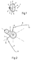
- this figure schematically shows a lighting device 1 according to the invention comprising a source of light 2 (bulb) and a reflector 3. No prismatic transparent cover is present.
- the reflector 3 is here imagined to be divided into four portions 4 corresponding to four quarter surfaces bounded by a horizontal section line 5 and by a vertical section line 6.
- first to be generated is the surface of a portion 4, after which the other three portions are generated by reflection in order together to yield the complete surface.
- Figure 2 shows curve 5 defining the horizontal section and curve 6 defining the vertical section of the reflector 3; also shown is the guide line 7 for the transformation by which horizontal curve 5 is moved to vertical curve 6 (or vice versa).
- horizontal curve 5 and vertical curve 6 are generated first of all, in such a way as to give the desired distribution of the light, already having the final output distribution of the lighting device 1.
- Examples of the distribution of light suitable for motor vehicle lamps for curve 5 defining the horizontal section and for curve 6 defining the vertical section are shown in Figures 4 and 5.
- Curves 5 and 6 can be produced either graphically on a computer, starting with basic curves such as parabolic curves and gradually modifying them graphically until the desired distribution is obtained, or starting with non-rational parametric curves described by equations of the following type: or rational curves with equations of the following type: in which b i are the co-ordinates of the vertices of the polygons, B i (t) are Bernstein functions and w are weightings.
- the surface of a portion 4 of the reflector 3 is generated by sliding the curve 5, which corresponds to the horizontal section, along the guide curve 7 and changing its shape as it moves in such a way as to transform it gradually into curve 6 which corresponds to the vertical section.
- This sliding advantageously performed on a computer using a graphic design programme (CAD), moves the inward end of curve 5 (marked 10 in Figure 2) to the inward end 11 of curve 6 along the guide curve 7.
- CAD graphic design programme
- the surface 4 produced graphically in this way is then reflected to produce the other three surface portions 4 (axial symmetry).
- dispensing with the diffusing lens brings three advantages: it eliminates the stray light which in known lighting devices was caused by scattering by the external lens into regions where less light is wanted; it improves the visual appearance of the lighting device; and it lowers the cost of manufacturing the lighting device in terms of both the lens material and the moulding of the lens.
- the device according to the invention can be made to the necessary dimensions, and the dimensions can even be reduced.
- the lighting device described and illustrated herein can be modified and altered without thereby departing from the protective scope of the present invention.
- the basic curves used to construct the surface may be different, provided they distribute the light in the desired manner, and may be generated mathematically or graphically by computer; the surface may also be made up of a different number of portions, for example three, with one being generated by the method described and the other two generated by reflection; indeed, the surface may even comprise only the portion generated by transformation, since this portion is already able to distribute the light in the desired manner.
Landscapes
- Engineering & Computer Science (AREA)
- General Engineering & Computer Science (AREA)
- Non-Portable Lighting Devices Or Systems Thereof (AREA)
- Lighting Device Outwards From Vehicle And Optical Signal (AREA)
Description
- Figure 1 is a schematic perspective view of a lighting device according to the invention;
- Figure 2 is an isometric view of the horizontal and vertical sections through the reflector of the present device;
- Figure 3 shows the modification of the sections as they pass from the horizontal section to the vertical section of the present reflector; and
- Figures 4 and 5 show the distribution of the luminous flux produced by the horizontal section and vertical section respectively.


Claims (6)
- Lighting device (1) for a motor vehicle, comprising a light source (2) capable of generating a light beam and a reflector (3) capable of distributing said light beam in space, said reflector (3) being a non-parabolic reflector with a continuous complex reflective surface; the device being characterized in that said reflective surface of said reflector (3) comprises at least one surface portion (4) bounded by a first and a second section lines (5, 6), said section lines (5, 6) being designed in such a way as to directly distribute the luminous flux in a desired manner, according to the regulations, on the section line in question; said at least one surface portion (4) is generated from said section lines (5, 6) by a transformation of said first section line (5) into said second section line (6) carried out by sliding one end (10) of said first section line (5) along a guide line (7) to a corresponding end (11) on said second section line (6), in such a way that each point on said first section line is moved continuously to a corresponding point on said second section line.
- Lighting device according to Claim 1, characterized in that it has no diffusing prismatic lens means.
- Lighting device according to Claim 1 or 2, characterized in that said first section line (5) is a horizontal section line and said second section line (6) is a vertical section line, said lines being perpendicular to each other.
- Lighting device according to any one of Claims 1 to 3, characterized in that it comprises a plurality of surface portions (4) generated by reflecting said one or more surface portions (4).
- Lighting device according to any one of Claims 1 to 4, characterized in that said first and second section lines (5, 6) are described by rational or irrational parametric curves.
- Lighting device according to any one of Claims 1 to 4, characterized in that said first and second section lines (5, 6) are generated graphically by the manual deforming of parabolic basic curves.
Applications Claiming Priority (2)
| Application Number | Priority Date | Filing Date | Title |
|---|---|---|---|
| IT95TO000381A IT1279204B1 (en) | 1995-05-12 | 1995-05-12 | LIGHTING DEVICE FOR MOTOR VEHICLES |
| ITTO950381 | 1995-05-12 |
Publications (2)
| Publication Number | Publication Date |
|---|---|
| EP0742407A1 EP0742407A1 (en) | 1996-11-13 |
| EP0742407B1 true EP0742407B1 (en) | 2000-09-13 |
Family
ID=11413552
Family Applications (1)
| Application Number | Title | Priority Date | Filing Date |
|---|---|---|---|
| EP96107397A Expired - Lifetime EP0742407B1 (en) | 1995-05-12 | 1996-05-09 | Lighting device for a motor vehicle |
Country Status (4)
| Country | Link |
|---|---|
| EP (1) | EP0742407B1 (en) |
| DE (1) | DE69610245T2 (en) |
| ES (1) | ES2151103T3 (en) |
| IT (1) | IT1279204B1 (en) |
Families Citing this family (1)
| Publication number | Priority date | Publication date | Assignee | Title |
|---|---|---|---|---|
| US6811289B2 (en) * | 2001-01-22 | 2004-11-02 | Ichikoh Industries, Ltd. | Lamp device for a vehicle having a free curved surface and a lens without a prism |
Family Cites Families (2)
| Publication number | Priority date | Publication date | Assignee | Title |
|---|---|---|---|---|
| US4495552A (en) * | 1982-12-13 | 1985-01-22 | Cal Custom Accessories, Inc. | Forward shining vehicle lamp |
| JP3207031B2 (en) * | 1993-10-01 | 2001-09-10 | 株式会社小糸製作所 | Reflector for vehicle lighting |
-
1995
- 1995-05-12 IT IT95TO000381A patent/IT1279204B1/en active IP Right Grant
-
1996
- 1996-05-09 ES ES96107397T patent/ES2151103T3/en not_active Expired - Lifetime
- 1996-05-09 EP EP96107397A patent/EP0742407B1/en not_active Expired - Lifetime
- 1996-05-09 DE DE69610245T patent/DE69610245T2/en not_active Expired - Fee Related
Also Published As
| Publication number | Publication date |
|---|---|
| ES2151103T3 (en) | 2000-12-16 |
| EP0742407A1 (en) | 1996-11-13 |
| DE69610245T2 (en) | 2001-02-22 |
| ITTO950381A1 (en) | 1996-11-12 |
| DE69610245D1 (en) | 2000-10-19 |
| ITTO950381A0 (en) | 1995-05-12 |
| IT1279204B1 (en) | 1997-12-04 |
Similar Documents
| Publication | Publication Date | Title |
|---|---|---|
| US5997156A (en) | Lighting device for generating a rectangular pattern at the work area, E. G. for illuminating pedestrian crossings | |
| CN105980770B (en) | Motor vehicle lamp with light conductor | |
| US4945454A (en) | Reflector for dimmed or dimmable motor vehicle headlights | |
| JPS63168902A (en) | Signal lamp with less depth for automobile | |
| US5204820A (en) | Method of producing an optically effective arrangement in particular for application with a vehicular headlight | |
| US20080175015A1 (en) | Light source or signaling module with improved appearance | |
| US5065287A (en) | Method of producing an optically effective arrangement, in particular for application with a vehicular headlight | |
| US11359792B2 (en) | Lighting device | |
| JPH1166917A (en) | Indicator lights for automobiles | |
| JPH10116505A (en) | Automotive indicator light | |
| US5117336A (en) | Working spotlight, particularly for motor vehicles | |
| US5777809A (en) | Reflection mirror for a vehicle lamp and a method of forming the same | |
| US5483430A (en) | Multi-faceted light reflector | |
| US6493096B1 (en) | Method of determining reflective surface of reflector in vehicle lamp | |
| US10480745B1 (en) | Arranged light pipes for automotive lighting systems | |
| EP0742407A1 (en) | Lighting device for a motor vehicle | |
| US6578996B1 (en) | Method of designing reflective surface of reflector in vehicle lamp | |
| Domhardt et al. | New design tools for LED headlamps | |
| US6186652B1 (en) | Motor vehicle headlamp having a reflector giving selective light deviation, and methods of making such a reflector | |
| US11255511B2 (en) | Optical device for modifying light distribution | |
| GB2360378A (en) | Determining reflective surface | |
| US6010233A (en) | Automobile headlamp reflector | |
| EP1505339A1 (en) | Complex reflector for a vehicle headlight, and method for the manufacture of the reflector | |
| EP1300627B1 (en) | Headlamp | |
| US5645339A (en) | Vehicle headlamp construction for a well defined lower beam pattern |
Legal Events
| Date | Code | Title | Description |
|---|---|---|---|
| PUAI | Public reference made under article 153(3) epc to a published international application that has entered the european phase |
Free format text: ORIGINAL CODE: 0009012 |
|
| AK | Designated contracting states |
Kind code of ref document: A1 Designated state(s): DE ES FR GB |
|
| 17P | Request for examination filed |
Effective date: 19960928 |
|
| 17Q | First examination report despatched |
Effective date: 19990212 |
|
| GRAG | Despatch of communication of intention to grant |
Free format text: ORIGINAL CODE: EPIDOS AGRA |
|
| GRAG | Despatch of communication of intention to grant |
Free format text: ORIGINAL CODE: EPIDOS AGRA |
|
| GRAH | Despatch of communication of intention to grant a patent |
Free format text: ORIGINAL CODE: EPIDOS IGRA |
|
| RAP1 | Party data changed (applicant data changed or rights of an application transferred) |
Owner name: AUTOMOTIVE LIGHTING ITALIA SPA |
|
| GRAH | Despatch of communication of intention to grant a patent |
Free format text: ORIGINAL CODE: EPIDOS IGRA |
|
| RIC1 | Information provided on ipc code assigned before grant |
Free format text: 7F 21V 7/09 A |
|
| GRAA | (expected) grant |
Free format text: ORIGINAL CODE: 0009210 |
|
| AK | Designated contracting states |
Kind code of ref document: B1 Designated state(s): DE ES FR GB |
|
| REF | Corresponds to: |
Ref document number: 69610245 Country of ref document: DE Date of ref document: 20001019 |
|
| ET | Fr: translation filed | ||
| REG | Reference to a national code |
Ref country code: ES Ref legal event code: FG2A Ref document number: 2151103 Country of ref document: ES Kind code of ref document: T3 |
|
| PGFP | Annual fee paid to national office [announced via postgrant information from national office to epo] |
Ref country code: GB Payment date: 20010516 Year of fee payment: 6 |
|
| PGFP | Annual fee paid to national office [announced via postgrant information from national office to epo] |
Ref country code: ES Payment date: 20010524 Year of fee payment: 6 |
|
| PLBE | No opposition filed within time limit |
Free format text: ORIGINAL CODE: 0009261 |
|
| STAA | Information on the status of an ep patent application or granted ep patent |
Free format text: STATUS: NO OPPOSITION FILED WITHIN TIME LIMIT |
|
| 26N | No opposition filed | ||
| REG | Reference to a national code |
Ref country code: GB Ref legal event code: IF02 |
|
| PG25 | Lapsed in a contracting state [announced via postgrant information from national office to epo] |
Ref country code: GB Free format text: LAPSE BECAUSE OF NON-PAYMENT OF DUE FEES Effective date: 20020509 |
|
| PG25 | Lapsed in a contracting state [announced via postgrant information from national office to epo] |
Ref country code: ES Free format text: LAPSE BECAUSE OF NON-PAYMENT OF DUE FEES Effective date: 20020510 |
|
| GBPC | Gb: european patent ceased through non-payment of renewal fee |
Effective date: 20020509 |
|
| REG | Reference to a national code |
Ref country code: ES Ref legal event code: FD2A Effective date: 20030611 |
|
| PGFP | Annual fee paid to national office [announced via postgrant information from national office to epo] |
Ref country code: DE Payment date: 20050719 Year of fee payment: 10 |
|
| PG25 | Lapsed in a contracting state [announced via postgrant information from national office to epo] |
Ref country code: DE Free format text: LAPSE BECAUSE OF NON-PAYMENT OF DUE FEES Effective date: 20061201 |
|
| REG | Reference to a national code |
Ref country code: FR Ref legal event code: PLFP Year of fee payment: 20 |
|
| PGFP | Annual fee paid to national office [announced via postgrant information from national office to epo] |
Ref country code: FR Payment date: 20150422 Year of fee payment: 20 |