EP0741958B1 - Housing with heat-liberating equipment - Google Patents
Housing with heat-liberating equipment Download PDFInfo
- Publication number
- EP0741958B1 EP0741958B1 EP95936052A EP95936052A EP0741958B1 EP 0741958 B1 EP0741958 B1 EP 0741958B1 EP 95936052 A EP95936052 A EP 95936052A EP 95936052 A EP95936052 A EP 95936052A EP 0741958 B1 EP0741958 B1 EP 0741958B1
- Authority
- EP
- European Patent Office
- Prior art keywords
- fins
- heat
- units
- rack
- housing
- Prior art date
- Legal status (The legal status is an assumption and is not a legal conclusion. Google has not performed a legal analysis and makes no representation as to the accuracy of the status listed.)
- Expired - Lifetime
Links
- 230000037361 pathway Effects 0.000 claims description 13
- 230000000694 effects Effects 0.000 claims description 6
- 239000003570 air Substances 0.000 description 23
- 238000001816 cooling Methods 0.000 description 21
- 238000012546 transfer Methods 0.000 description 8
- 238000013461 design Methods 0.000 description 5
- 238000005266 casting Methods 0.000 description 4
- 229910000838 Al alloy Inorganic materials 0.000 description 1
- QPLDLSVMHZLSFG-UHFFFAOYSA-N Copper oxide Chemical compound [Cu]=O QPLDLSVMHZLSFG-UHFFFAOYSA-N 0.000 description 1
- 239000005751 Copper oxide Substances 0.000 description 1
- 239000004677 Nylon Substances 0.000 description 1
- XAGFODPZIPBFFR-UHFFFAOYSA-N aluminium Chemical compound [Al] XAGFODPZIPBFFR-UHFFFAOYSA-N 0.000 description 1
- 229910052782 aluminium Inorganic materials 0.000 description 1
- 239000012080 ambient air Substances 0.000 description 1
- 238000005452 bending Methods 0.000 description 1
- 230000005540 biological transmission Effects 0.000 description 1
- 230000003749 cleanliness Effects 0.000 description 1
- 238000010276 construction Methods 0.000 description 1
- 229910000431 copper oxide Inorganic materials 0.000 description 1
- 238000011161 development Methods 0.000 description 1
- 230000002708 enhancing effect Effects 0.000 description 1
- 230000017525 heat dissipation Effects 0.000 description 1
- 230000001771 impaired effect Effects 0.000 description 1
- 238000009434 installation Methods 0.000 description 1
- 238000012423 maintenance Methods 0.000 description 1
- 238000004519 manufacturing process Methods 0.000 description 1
- 239000000463 material Substances 0.000 description 1
- 238000000034 method Methods 0.000 description 1
- 229920001778 nylon Polymers 0.000 description 1
- 230000005693 optoelectronics Effects 0.000 description 1
- 238000013021 overheating Methods 0.000 description 1
- 239000012815 thermoplastic material Substances 0.000 description 1
Images


Classifications
-
- H—ELECTRICITY
- H05—ELECTRIC TECHNIQUES NOT OTHERWISE PROVIDED FOR
- H05K—PRINTED CIRCUITS; CASINGS OR CONSTRUCTIONAL DETAILS OF ELECTRIC APPARATUS; MANUFACTURE OF ASSEMBLAGES OF ELECTRICAL COMPONENTS
- H05K7/00—Constructional details common to different types of electric apparatus
- H05K7/20—Modifications to facilitate cooling, ventilating, or heating
- H05K7/20536—Modifications to facilitate cooling, ventilating, or heating for racks or cabinets of standardised dimensions, e.g. electronic racks for aircraft or telecommunication equipment
- H05K7/20545—Natural convection of gaseous coolant; Heat transfer by conduction from electronic boards
Definitions
- the invention relates to enclosed units, such as electronics or optoelectronics units, which liberate heat that must be rejected to the environment through the walls of the housing which encloses the unit.
- enclosed units such as electronics or optoelectronics units
- the invention has particular applicability to equipments having a plurality of units of this type which are mounted one above the other in a rack or cabinet (for simplicity, hereafter referred to simply as a rack).
- integral fins to increase surface area and promote cooling goes far back in the age of machinery. Enough heat is liberated in machinery because of friction, thermodynamic or other processes so that some structure besides the basic machine parts was required to enhance cooling by the surrounding air.
- Devices like air compressors have long been made with fins cast onto the cylinders. Such fins generally extend radially and longitudinally, or radially in planes perpendicular to the cylinder axis.
- Copper oxide rectifier stacks were made with very large disc cooling fins between diodes of the stack.
- Some high power tubes were made with integral cooling fins, generally lying in longitudinally extending radial planes. With such tubes it was important that they be mounted in a vertical attitude.
- the first cooling improvement was radial fin devices that could be slipped over a transistor can. Later the higher power transistors were made such that the can was held against a large plate at the outside rear of an apparatus, and the plate had a number of vertical cooling fins on its exterior.
- U.S. patent 4,237,521 teaches the use of a diagonal fin arrangement to facilitate cooling of a wall used as a heat sink for components such as transistors in a radio receiver. These transistors are generally mounted in intimate thermal contact with the heat sink. By arranging the fins obliquely to the vertical, adequate convection cooling could be provided for intermittent use; while for continuous use forced air cooling could be obtained by a fan placed behind the unit to withdraw heated air horizontally.
- a CATV equipment housing is made of two cast sections, and has fins on all sides. On the two major walls the fins extend diagonally between the fins on the other sides of the housing.
- a further improvement in cooling effectiveness is claimed for a fin design shown in US patent 5,150,278.
- the fins are aligned in rows on one major surface having a long dimension, diagonal to the long dimension, and are interrupted by gaps which define angle channels oriented parallel to the long dimension, 30° to 60° from the row channels.
- This arrangement is described as providing improved air flow along the row channels because of reduced friction, and also allowing extra air flow along the angle channels.
- This housing is intended for mounting with the finned surface in a vertical plane, but the long dimension may be either vertical, such as when the unit is in a "pillar" enclosure, or horizontal, such as when the unit is hung from a wire stretched between poles. Cable connections to the unit are made at opposite ends, so that in a pillar mount one connector is in the top surface and the cable arches up away from the unit.
- CATV housing described in the '278 patent clearly is intended for use alone, so that no provision is made to preventing overheating of the top unit of a stack. If units, especially units like that shown in the '521 patent, are rack mounted, the only solution to high ambient temperatures around the top of a rack or cabinet has been to provide forced air cooling. This is disadvantageous because of cost, noise, and reliability considerations for small high speed fans.
- heat-liberating units which have fins arranged obliquely on vertical surfaces are mounted as a vertical stack in a rack.
- the rack has a space extending past the units of the stack, adjacent the upper ends of at least some of the fins, which defines a pathway producing a chimney effect for upward flow of heated air from the upper ends of the fins; and the rack is arranged to define a pathway for unheated surrounding air to lower ends of at least some of the fins on all these units. If a group of vertically aligned units are double sided (that is, have fins on two sides of each unit) then the dimensions of these units in plan view need merely be sufficiently similar that the oblique flow of air between the pathways is maintained effectively.
- the rack For cleanliness and comfort of people who service or must have access to the units, it is advantageous to arrange the rack so that the hot air chimney is at the rear. Fronts of the individual units may be exposed to the surrounding air, or may be behind a cabinet door which defines a path for cool ambient air to flow to each of the units. However, in specific installations the relative positions of cool and hot pathways may be different.
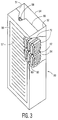
- the telecommunication unit shown in Figs. 1 and 2 may be used for CATV/Telephony transmission and reception, handling signals at frequencies from 5 Mhz to 1 Ghz.
- a housing cool section 10 is provided with equally spaced cooling fins 12 extending upwardly and rearwardly.
- a laser diode 13 (shown schematically), whose performance will be seriously impaired if its temperature exceeds 65°C, is mounted on a PC board 14, via a heat sink 15 which is fastened by a screw or more permanent means to a wall portion or plate 17 on which the fins 12 are formed. This configuration enhances heat transfer from the diode to the housing section 10 and then to the cooling air flow.
- a housing hot section 20 is also provided with equally spaced cooling fins 22 extending upwardly and rearwardly.
- a plurality of transistors 23 are mounted on a PC board 24. These transistors have heat sinks 25 which are attached to a wall portion or plate 27 of the housing section 20 by screws, to enhance heat transfer from the transistors to the housing section.
- the side plates 17 and 27 are each formed by casting from an easy-casting aluminum alloy.
- the two side plates are separated by a thermally insulating gasket 30 made of an inexpensive thermoplastic material such as nylon.
- the gasket may be eliminated, and a simple gap or open slot may separate the two side plates.
- the fins 12 are aligned with, but spaced from, the fins 22 so that they define cooling air flow channels.
- the hot section side plate 22 may include an end portion perpendicular to the side wall.
- the cool section side plate 12 can include an end portion. This is especially desirable if a cable socket should be placed close to the diode 13. If the side plates are mechanically connected by an insulating or low conductivity internal structure, then all electrical assembly can be performed easily before attachment of a cover.
- a cover 32 is fastened to both side plates by screws.
- the cover 32 may be made of thin aluminum sheet material, and may also be perforated if dust-tightness is not required. Where the side plates include end portions, the cover then is easily formed by bending into a "U" shape.
- a further gasket portion may be provided between the cover and the side plate 17; the inside of the cover 32 may be insulated at the cool end; or some thermal shielding may be provided around the cool end components to reduce convection air currents within the unit.
- the dimensions of the thermally insulating gap or gasket will usually not be critical. Depending in part on the wall thicknesses, a gap length or gasket thickness might be as small as 0.5 mm (.020") or even less. To reduce thermal transfer between the sections, the wall thickness can be reduced greatly adjacent the gap or gasket. To prevent excessive RF leakage, a maximum gap of approximately 1% of the shortest wavelength of concern will usually suffice. For critical applications, perforations in the cover may be omitted, or made very small. A shield plate or screen can bridge the gap, and can easily be made to minimize thermal conduction between the two side plates.
- the cover 32 actually holds the cool section side plate 12 in position. It will be clear that this is just one of many construction expedients. As discussed above, an internal structure may interconnect the two side plates. Instead of making two separate side plates 17 and 27, it is possible to cast them as one piece, with a slot formed to provide two thin portions interconnecting cool and hot portions of the plate. Functionally the unit still has two housing sections.
- This design is suitable for units which have one cable connection (not shown) to the cool housing section, and one or more to the hot section.
- the rack 50 has side walls 51 and 52, a rear wall 54, a front door 56 having louver openings 57, and an internal frame 58 including appropriate cross pieces for mounting rows of units 60, 62 one above the other. Between the rear surfaces of the units 60, 62 and the rear wall 54 a rear pathway 64 for air heated by the units 60 will provide a chimney effect, greatly increasing the cooling of the units. This rear pathway also provides space for cables (not shown) connecting to the units 60, 62. To aid in defining the chimney effect, the front portion of the cabinet may also have a top cover 66.
- the units 60 may be identical to those shown in Figs. 1 and 2.
- the units 62 are exemplary of a design for units with a higher heat dissipation, and have fins 72 on both sides. Such a unit may have separate castings for the two sides of the hot housing section, and one casting for the cool section.
- the front door 56 provides access for any cables connected to the cool sections of the units 60, 62.
- the space between the front door 56 and the fronts (cool housing sections) of the units 60 and 62 forms a pathway 80 for surrounding air.
- the fins need not be straight. Curvature, or irregularities in the fin surfaces, or variation in fin thickness may be used to improve the overall cooling effect, or to increase thermal transfer to the air at one region of the channels compared with another. In some applications the fins may not be evenly spaced; or some or all of the spacings on one section may differ from those on the other. This last possibility necessarily implies that the fins or the two sections will not be fully in line with each other.
- heat sensitive elements such as the diode 13 may be mounted adjacent to but not touching the cool housing section 10, or be located somewhat remotely from the plate 17.
- circuit considerations call for placing a heat sensitive component near a component in the hot section
- a special advantage of the invention allows insulating the heat sensitive component somewhat from the hotter component in the hot section, and enhancing heat transfer from the temperature sensitive component to the cool section by a heat pipe or other high thermal conductivity element.
- the hot section may be at the housing front.
- This design requires that the door be kept closed except for brief maintenance periods; and that any louvers be confined to the extreme top or bottom.
- the rack be elevated above any floor, and that most cooling air enter the cabinetry toward the rear. Side to side cooling flow is also possible, and allows easy entry of cool air and exit of hot air, but this arrangement usually impairs access to units toward the rear of the cabinet.
Landscapes
- Engineering & Computer Science (AREA)
- Aviation & Aerospace Engineering (AREA)
- Physics & Mathematics (AREA)
- Thermal Sciences (AREA)
- Microelectronics & Electronic Packaging (AREA)
- Cooling Or The Like Of Electrical Apparatus (AREA)
Description
Claims (4)
- A heat-liberating equipment, comprising:a plurality of heat-liberating units (60), each unit having a housing (10) and at least one heat-liberating element mounted within said housing, each respective housing having a side surface (17, 27) extending generally vertically, each said side surface having a plurality of heat-dissipating fins (12) protruding therefrom, each of said fins being inclined between approximately 30° and approximately 60° from vertical, and each of said fins having a respective lower end and an upper end,a partially enclosed rack (50) including means for mounting said heat-liberating units (60) as a vertical stack in said rack,
arranged such that said side surfaces are aligned vertically above each other with the respective fins being inclined in the same direction,said rack being arranged to define a pathway (80) for flow of surrounding air to said lower ends of said fins, and a further pathway (64) producing a chimney effect for upward flow of heated air from said upper ends. - An equipment as claimed in claim 1, characterized in that at least a group of said plurality of units have substantially similar external dimensions in plan view, and
each of the units of said group are mounted in a vertical line, and have two said side surfaces extending parallel to each other, with the respective fins being substantially parallel to each other. - An equipment as claimed in claim 2, characterized in that said pathway (80) for flow of surrounding air extends along a front of said rack, and said further pathway (64) for upward flow of heated air extends along a back of said rack.
- A telecommunications equipment, comprising:a plurality of heat-liberating units (60), each unit having a housing (10) and at least one heat-liberating element mounted within said housing, each respective housing having a side surface (17, 27) extending generally vertically, each said side surface having a plurality of heat-dissipating fins (12) protruding therefrom, each of said fins being inclined between approximately 30° and approximately 60° from vertical, and each of said fins having a respective lower end and an upper end,a partially enclosed rack (50) including means for mounting said heat-liberating units (60) as a vertical stack in said rack,
arranged such that said side surfaces are aligned vertically above each other with the respective fins being inclined in the same direction,said rack being arranged to define a pathway (80) for flow of surrounding air to said lower ends of said fins, and a further pathway (64) producing a chimney effect for upward flow of heated air from said upper ends.
Applications Claiming Priority (3)
| Application Number | Priority Date | Filing Date | Title |
|---|---|---|---|
| US08/345,166 US5513071A (en) | 1994-11-28 | 1994-11-28 | Electronics housing with improved heat rejection |
| US345166 | 1994-11-28 | ||
| PCT/IB1995/001015 WO1996017506A1 (en) | 1994-11-28 | 1995-11-16 | Housing with equipment heat-liberating |
Publications (2)
| Publication Number | Publication Date |
|---|---|
| EP0741958A1 EP0741958A1 (en) | 1996-11-13 |
| EP0741958B1 true EP0741958B1 (en) | 1999-06-23 |
Family
ID=23353833
Family Applications (1)
| Application Number | Title | Priority Date | Filing Date |
|---|---|---|---|
| EP95936052A Expired - Lifetime EP0741958B1 (en) | 1994-11-28 | 1995-11-16 | Housing with heat-liberating equipment |
Country Status (5)
| Country | Link |
|---|---|
| US (1) | US5513071A (en) |
| EP (1) | EP0741958B1 (en) |
| JP (1) | JPH09509014A (en) |
| DE (1) | DE69510443T2 (en) |
| WO (1) | WO1996017506A1 (en) |
Families Citing this family (44)
| Publication number | Priority date | Publication date | Assignee | Title |
|---|---|---|---|---|
| US5894407A (en) * | 1997-03-28 | 1999-04-13 | Lucent Technologies, Inc. | Enclosures for heat producing devices |
| US6065530A (en) * | 1997-05-30 | 2000-05-23 | Alcatel Usa Sourcing, L.P. | Weatherproof design for remote transceiver |
| US6082441A (en) * | 1997-06-13 | 2000-07-04 | Knuerr-Mechanik Fuer Die Elektronik Aktiengellschaft | Cabinet for electric and electronic systems |
| US6104602A (en) * | 1997-07-31 | 2000-08-15 | General Electric Company | Compact electrical equipment enclosure |
| US5915466A (en) * | 1998-01-19 | 1999-06-29 | Lucent Technologies Inc. | Heat dissipating structure for an electrical assembly |
| US5914857A (en) * | 1998-03-30 | 1999-06-22 | International Business Machines Corporation | Air flow devices for electronic boards |
| US5953930A (en) * | 1998-03-31 | 1999-09-21 | International Business Machines Corporation | Evaporator for use in an extended air cooling system for electronic components |
| US6223810B1 (en) | 1998-03-31 | 2001-05-01 | International Business Machines | Extended air cooling with heat loop for dense or compact configurations of electronic components |
| DE59914640D1 (en) | 1998-04-08 | 2008-03-20 | Fujitsu Siemens Computers Gmbh | DEVICE FOR COOLING A PERSONNEL COMPUTER SUBJECT TO A HOUSING |
| US6157546A (en) | 1999-03-26 | 2000-12-05 | Ericsson Inc. | Shielding apparatus for electronic devices |
| JP2000299965A (en) * | 1999-04-12 | 2000-10-24 | Calsonic Kansei Corp | Heat sink structure for fan controller |
| JP4023054B2 (en) * | 1999-12-07 | 2007-12-19 | 株式会社デンソー | Electronic circuit unit |
| DE10001735B4 (en) * | 2000-01-17 | 2006-07-06 | Pilz Gmbh & Co. Kg | Protection against unwanted commissioning of a machine plant |
| US6657121B2 (en) * | 2001-06-27 | 2003-12-02 | Thermal Corp. | Thermal management system and method for electronics system |
| US6459577B1 (en) * | 2001-07-06 | 2002-10-01 | Apple Computer, Inc. | Thermal chimney for a computer |
| US6536510B2 (en) | 2001-07-10 | 2003-03-25 | Thermal Corp. | Thermal bus for cabinets housing high power electronics equipment |
| US6388882B1 (en) | 2001-07-19 | 2002-05-14 | Thermal Corp. | Integrated thermal architecture for thermal management of high power electronics |
| US6856037B2 (en) * | 2001-11-26 | 2005-02-15 | Sony Corporation | Method and apparatus for converting dissipated heat to work energy |
| US20030221817A1 (en) * | 2002-05-31 | 2003-12-04 | Racksaver, Inc. | Rack mountable computer component cooling method and device |
| US7198094B2 (en) * | 2003-06-20 | 2007-04-03 | Hewlett-Packard Development Company, L.P. | Finned device for removing heat from an electronic component |
| US20050257912A1 (en) * | 2004-01-12 | 2005-11-24 | Litelaser Llc | Laser cooling system and method |
| US7201651B2 (en) * | 2004-12-22 | 2007-04-10 | Chi-Min Su | Louver heat vent for chassis of computer |
| US7283358B2 (en) * | 2005-07-19 | 2007-10-16 | International Business Machines Corporation | Apparatus and method for facilitating cooling of an electronics rack by mixing cooler air flow with re-circulating air flow in a re-circulation region |
| US8240359B2 (en) * | 2006-04-17 | 2012-08-14 | Gerald Garrett | Liquid storage and cooling computer case |
| EP1855363B1 (en) * | 2006-05-11 | 2012-12-12 | I.R.E. Industria Resistenze Elettriche S.R.L. | Cabinet for electrical elements that generate heat to be dissipated |
| US8264856B2 (en) | 2006-08-18 | 2012-09-11 | Delphi Technologies, Inc. | Lightweight audio system for automotive: applications and method |
| US7733659B2 (en) | 2006-08-18 | 2010-06-08 | Delphi Technologies, Inc. | Lightweight audio system for automotive applications and method |
| US9237685B2 (en) | 2006-08-18 | 2016-01-12 | Delphi Technologies, Inc. | Lightweight audio system for automotive applications and method |
| WO2008029636A1 (en) * | 2006-09-04 | 2008-03-13 | Kabushiki Kaisha Yaskawa Denki | Motor control device |
| US7391610B2 (en) | 2006-09-29 | 2008-06-24 | Rockwell Automation Technologies, Inc. | Thermal cooling of industrial electronic module by conductive structure |
| US8291965B2 (en) * | 2007-03-27 | 2012-10-23 | Adc Telecommunications, Inc. | Heat sink with angled fins |
| US7535716B2 (en) * | 2007-05-23 | 2009-05-19 | Adc Telecommunications, Inc. | Apparatus for enclosing electronic components used in telecommunication systems |
| US8253076B2 (en) * | 2007-10-29 | 2012-08-28 | Smiths Medical Asd, Inc. | Respiratory system heater unit |
| CA2629493A1 (en) * | 2008-04-18 | 2009-10-18 | Mabe Canada Inc. | Clothes dryer with louvre cover |
| JP5405043B2 (en) * | 2008-04-22 | 2014-02-05 | 株式会社小糸製作所 | Vehicle lighting |
| CA2764322C (en) | 2009-06-11 | 2015-10-27 | Relume Technologies, Inc. | Solar shield for led light emitting assembly |
| US8451604B2 (en) * | 2010-09-27 | 2013-05-28 | Intel Corporation | Chimney-based cooling mechanism for computing devices |
| US10209003B2 (en) | 2012-02-21 | 2019-02-19 | Thermal Corp. | Electronics cabinet and rack cooling system and method |
| DE102014201483B4 (en) * | 2014-01-28 | 2016-04-07 | Wago Verwaltungsgesellschaft Mbh | Cuboid housing for an electronics module, electronic module and arrangement for cooling at least one electronic module |
| DE102015016260A1 (en) * | 2015-12-15 | 2017-06-22 | Wilo Se | Electronics housing with cooling fins |
| KR101794007B1 (en) * | 2016-04-06 | 2017-11-07 | (주)휴맥스 | Eradiation module assembly and set top box having the same |
| JP6673889B2 (en) | 2017-10-31 | 2020-03-25 | ファナック株式会社 | Electronic equipment |
| WO2019151914A1 (en) * | 2018-02-02 | 2019-08-08 | Telefonaktiebolaget Lm Ericsson (Publ) | Cooling device for dissipating heat from an object |
| EP4415495A1 (en) * | 2023-02-09 | 2024-08-14 | Abb Schweiz Ag | Automation device for an electric drive device and an electric drive device |
Family Cites Families (11)
| Publication number | Priority date | Publication date | Assignee | Title |
|---|---|---|---|---|
| US336074A (en) * | 1886-02-09 | Assigfoe to joseph f | ||
| US4027206A (en) * | 1975-01-27 | 1977-05-31 | L. H. Research | Electronic cooling chassis |
| US4237521A (en) * | 1979-02-05 | 1980-12-02 | R. L. Drake Company | Housing for electronic assembly including internally mounted heat sink |
| JPS626720Y2 (en) * | 1981-05-14 | 1987-02-16 | ||
| US5105336A (en) * | 1987-07-29 | 1992-04-14 | Lutron Electronics Co., Inc. | Modular multilevel electronic cabinet |
| JP2720072B2 (en) * | 1988-09-09 | 1998-02-25 | 株式会社日立製作所 | Electronic equipment cooling device |
| US5065278A (en) * | 1990-01-29 | 1991-11-12 | Power Guard | Cast housing encased CATV power supply unit |
| US5150278A (en) * | 1991-04-16 | 1992-09-22 | J. E. Thomas Specialties Limited | Finned housing |
| JP2582577Y2 (en) * | 1992-11-04 | 1998-10-08 | 昭和アルミニウム株式会社 | Radiation fin |
| US5398159A (en) * | 1992-12-15 | 1995-03-14 | Telefonaktiebolaget Lm Ericsson | Modular packaging system |
| US5406451A (en) * | 1993-06-14 | 1995-04-11 | Comaq Computer Corporation | Heat sink for a personal computer |
-
1994
- 1994-11-28 US US08/345,166 patent/US5513071A/en not_active Expired - Fee Related
-
1995
- 1995-11-16 WO PCT/IB1995/001015 patent/WO1996017506A1/en not_active Ceased
- 1995-11-16 DE DE69510443T patent/DE69510443T2/en not_active Expired - Fee Related
- 1995-11-16 JP JP8518519A patent/JPH09509014A/en not_active Ceased
- 1995-11-16 EP EP95936052A patent/EP0741958B1/en not_active Expired - Lifetime
Also Published As
| Publication number | Publication date |
|---|---|
| US5513071A (en) | 1996-04-30 |
| DE69510443T2 (en) | 1999-12-16 |
| JPH09509014A (en) | 1997-09-09 |
| WO1996017506A1 (en) | 1996-06-06 |
| DE69510443D1 (en) | 1999-07-29 |
| EP0741958A1 (en) | 1996-11-13 |
Similar Documents
| Publication | Publication Date | Title |
|---|---|---|
| US5513071A (en) | Electronics housing with improved heat rejection | |
| US6065530A (en) | Weatherproof design for remote transceiver | |
| US5276584A (en) | Electronic unit | |
| US7408776B2 (en) | Conductive heat transport cooling system and method for a multi-component electronics system | |
| US6031720A (en) | Cooling system for semiconductor die carrier | |
| US7405936B1 (en) | Hybrid cooling system for a multi-component electronics system | |
| US4454566A (en) | Heat removal from cabinets housing electronic equipment | |
| US7031158B2 (en) | Heat pipe cooled electronics enclosure | |
| JP2001119181A (en) | Electronic component cooling device and electronic equipment | |
| US5912803A (en) | Heat dissipating box | |
| US4382271A (en) | Electrical and thermal interconnection system for electronic circuit boards and an electrical cabinet fitted with such a system | |
| US5999405A (en) | PCB module support system | |
| US6510053B1 (en) | Circuit board cooling system | |
| SE524893C2 (en) | Heat-conducting casing with diagonal-shaped flanged profiles | |
| JP4320401B2 (en) | Electronic device and mounting method thereof | |
| US7111674B2 (en) | Heat dissipating housing with interlocking chamfers and ESD resistance | |
| JP2806373B2 (en) | Electronic equipment cooling structure | |
| CN111615305A (en) | Plug box and magnetic resonance system | |
| JP2002010624A (en) | Power supply | |
| JPH066064A (en) | Dense installation device | |
| CN219496997U (en) | Server device | |
| JPH0730275A (en) | Electronic device cooling structure | |
| JPH06260784A (en) | Cooling apparatus | |
| CN215600793U (en) | Electric element protection shell used in electric cabinet | |
| JP7638817B2 (en) | Electronics Assembly |
Legal Events
| Date | Code | Title | Description |
|---|---|---|---|
| PUAI | Public reference made under article 153(3) epc to a published international application that has entered the european phase |
Free format text: ORIGINAL CODE: 0009012 |
|
| AK | Designated contracting states |
Kind code of ref document: A1 Designated state(s): DE FR GB |
|
| 17P | Request for examination filed |
Effective date: 19961206 |
|
| 17Q | First examination report despatched |
Effective date: 19980206 |
|
| GRAG | Despatch of communication of intention to grant |
Free format text: ORIGINAL CODE: EPIDOS AGRA |
|
| GRAG | Despatch of communication of intention to grant |
Free format text: ORIGINAL CODE: EPIDOS AGRA |
|
| GRAH | Despatch of communication of intention to grant a patent |
Free format text: ORIGINAL CODE: EPIDOS IGRA |
|
| GRAH | Despatch of communication of intention to grant a patent |
Free format text: ORIGINAL CODE: EPIDOS IGRA |
|
| GRAA | (expected) grant |
Free format text: ORIGINAL CODE: 0009210 |
|
| AK | Designated contracting states |
Kind code of ref document: B1 Designated state(s): DE FR GB |
|
| REF | Corresponds to: |
Ref document number: 69510443 Country of ref document: DE Date of ref document: 19990729 |
|
| ET | Fr: translation filed | ||
| PLBE | No opposition filed within time limit |
Free format text: ORIGINAL CODE: 0009261 |
|
| STAA | Information on the status of an ep patent application or granted ep patent |
Free format text: STATUS: NO OPPOSITION FILED WITHIN TIME LIMIT |
|
| 26N | No opposition filed | ||
| REG | Reference to a national code |
Ref country code: GB Ref legal event code: IF02 |
|
| REG | Reference to a national code |
Ref country code: GB Ref legal event code: 746 Effective date: 20020917 |
|
| REG | Reference to a national code |
Ref country code: FR Ref legal event code: D6 |
|
| PGFP | Annual fee paid to national office [announced via postgrant information from national office to epo] |
Ref country code: DE Payment date: 20040121 Year of fee payment: 9 |
|
| PGFP | Annual fee paid to national office [announced via postgrant information from national office to epo] |
Ref country code: FR Payment date: 20041125 Year of fee payment: 10 |
|
| PGFP | Annual fee paid to national office [announced via postgrant information from national office to epo] |
Ref country code: GB Payment date: 20041129 Year of fee payment: 10 |
|
| PG25 | Lapsed in a contracting state [announced via postgrant information from national office to epo] |
Ref country code: DE Free format text: LAPSE BECAUSE OF NON-PAYMENT OF DUE FEES Effective date: 20050601 |
|
| PG25 | Lapsed in a contracting state [announced via postgrant information from national office to epo] |
Ref country code: GB Free format text: LAPSE BECAUSE OF NON-PAYMENT OF DUE FEES Effective date: 20051116 |
|
| GBPC | Gb: european patent ceased through non-payment of renewal fee |
Effective date: 20051116 |
|
| PG25 | Lapsed in a contracting state [announced via postgrant information from national office to epo] |
Ref country code: FR Free format text: LAPSE BECAUSE OF NON-PAYMENT OF DUE FEES Effective date: 20060731 |
|
| REG | Reference to a national code |
Ref country code: FR Ref legal event code: ST Effective date: 20060731 |