EP0740615B1 - Writing instrument - Google Patents
Writing instrument Download PDFInfo
- Publication number
- EP0740615B1 EP0740615B1 EP95907121A EP95907121A EP0740615B1 EP 0740615 B1 EP0740615 B1 EP 0740615B1 EP 95907121 A EP95907121 A EP 95907121A EP 95907121 A EP95907121 A EP 95907121A EP 0740615 B1 EP0740615 B1 EP 0740615B1
- Authority
- EP
- European Patent Office
- Prior art keywords
- shaft
- cylindrical portion
- barrel
- retainer
- shoulder
- Prior art date
- Legal status (The legal status is an assumption and is not a legal conclusion. Google has not performed a legal analysis and makes no representation as to the accuracy of the status listed.)
- Expired - Lifetime
Links
- 230000007246 mechanism Effects 0.000 claims description 7
- 229920003023 plastic Polymers 0.000 claims description 6
- 239000004033 plastic Substances 0.000 claims description 6
- 239000000463 material Substances 0.000 claims description 4
- 239000007769 metal material Substances 0.000 claims description 4
- 238000010276 construction Methods 0.000 description 3
- 230000000694 effects Effects 0.000 description 2
- 238000000034 method Methods 0.000 description 2
- 229910001369 Brass Inorganic materials 0.000 description 1
- DHKHKXVYLBGOIT-UHFFFAOYSA-N acetaldehyde Diethyl Acetal Natural products CCOC(C)OCC DHKHKXVYLBGOIT-UHFFFAOYSA-N 0.000 description 1
- 125000002777 acetyl group Chemical class [H]C([H])([H])C(*)=O 0.000 description 1
- 239000010951 brass Substances 0.000 description 1
- 230000008030 elimination Effects 0.000 description 1
- 238000003379 elimination reaction Methods 0.000 description 1
Images




Classifications
-
- B—PERFORMING OPERATIONS; TRANSPORTING
- B43—WRITING OR DRAWING IMPLEMENTS; BUREAU ACCESSORIES
- B43K—IMPLEMENTS FOR WRITING OR DRAWING
- B43K24/00—Mechanisms for selecting, projecting, retracting or locking writing units
- B43K24/02—Mechanisms for selecting, projecting, retracting or locking writing units for locking a single writing unit in only fully projected or retracted positions
- B43K24/06—Mechanisms for selecting, projecting, retracting or locking writing units for locking a single writing unit in only fully projected or retracted positions operated by turning means
Definitions
- the present invention relates to writing instruments in general, and more particularly to a writing instrument having a mechanism for advancing and retracting the writing tip of the instrument wherein the mechanism is actuated by rotation of a knob disposed at the non-writing end of the pen barrel.
- a plunger assembly includes a rotatable knob which is disposed at the rear of the barrel and is interconnected to a finger which contacts a cam surface of a slidable actuator. Rotation of the knob in one direction advances the writing tip from within the barrel, and opposite rotation of the knob is effective to retract the writing tip into the barrel.
- knob attachment to the shaft of the plunger assembly may be accomplished by more firmly fixing the connection between the rotating knob assembly to the rotating shaft of the plunger assembly, while increasing the ease of protection of the knob during the actuating process.
- the Patent 3,679,318, issued to Thomas A. Liguori, discloses a writing instrument having a barrel and an advance and retract mechanism actuated by rotation of a knob disposed at the rear of the barrel opposite a writing tip.
- the writing instrument includes a shaft extending rearwardly form within the barrel to receive the knob for rotation of the shaft. The writing tip is advanced and retracted when the shaft is rotated by the knob.
- a writing instrument including a barrel and an advance-retract mechanism actuated by rotation of a knob disposed at the rear of said barrel opposite a writing tip at the forward end of said instrument, a shaft extending rearwardly from within said barrel to receive said knob for rotation of said shaft, said shaft being effective to advance and retract said writing tip when so rotated, characterized in that a retainer having a first cylindrical portion and a second cylindrical portion surrounds said shaft, in that said first cylindrical portion envelopes said shaft and has a plurality of rearwardly inwardly extending tangs contacting the surface of said shaft, and in that said second cylindrical portion is disposed forwardly of said first cylindrical portion and has a forward facing surface in spaced relation with a rearwardly facing end surface of said barrel.
- Biasing means is provided to force the retainer member rearwardly, and is disposed between the second cylindrical portion forward facing surface and the rear surface of the barrel.
- the biasing means is effective to force the tangs into the shaft and also provides a bearing surface between the retainer member and the barrel.
- the biasing means disclosed herein comprises a unitary bearing member, the bearing member having a cylindrical body through which the shaft extends and having a surface contacting the end surface of the barrel.
- a radially outwardly extending flange is disposed on the bearing member for contacting the forward facing surface of the retainer member.
- the unitary bearing member is generally formed of a resilient plastic material and the radially outwardly extending flange is compressible between the end surfaces of the barrel and the forward facing surface of the retainer member, causing the biasing action to force the tangs into the shaft.
- the shaft is generally formed of plastic and the retainer member is formed of a metallic material to provide the locking action between the retainer and the shaft when the metallic tangs are forced into the plastic shaft.
- biasing means may be deleted from the apparatus, thereby eliminating one piece from and simplifying the assembly process.
- a writing instrument 10 in the form of a ball point pen having an elongated writing assembly 12 disposed in a barrel 14.
- the various elements and the function of the writing assembly 12 are disclosed hereinafter with specific reference to Figures 20 through 24.
- the actuating member comprises a shaft 16 as shown in Figure 2, having a portion extending into the barrel 14, and a portion extending through an opening in the barrel for access by the user to rotate the shaft and thereby cause a finger 18 to manipulate those elements of the writing assembly 12, and move the writing tip into and out of the barrel 14.
- the barrel 14 has an opening 20 through which the shaft 16 extends, and a rivet 22 extends into the opening 20 having a planar surface 23 and a portion 24 which is peened over to encapsulate a clip 25.
- the shaft 16 extends outwardly through the opening 20 to a point at which a shoulder 26 of the shaft contacts the surface 22 of the rivet.
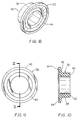
- the retainer 28 is shown to comprise a first cylindrical portion 32 which is of a size to substantially envelop the shaft 16 when inserted therein, and three inwardly extending tangs 33 which project inwardly to contact the shaft in interfitting engagement with the outer surface of the shaft.
- a second cylindrical portion 34 is disposed forwardly of the portion 32 and comprises a forward facing surface 36 with the retainer mounted as shown in Figure 1, the surface 36 being disposed in spaced relation with the barrel 14 which has the rivet 22 set in place.
- cylindrical portion 34 substantially forms a cup for retaining the bearing 30, however the forward edge of the retainer cylindrical portion 34 lies outside of the peened portion 24 of the rivet, thereby allowing only the bearing 30 to provide rotatable surfaces between the barrel 14 and the surface 36 of the retainer 28.
- the bearing 30 is of unitary construction and comprises a cylindrical body 38 through which the shaft 16 extends and a planar surface 40 which contacts the barrel 14 at the portion 24 of the rivet 22.
- a radially outwardly extending flange 42 is provided with a planar bearing surface 44 for contacting the forward facing surface 36 of the retainer 28. It will further be noted that the flange 42, in addition to extending radially outwardly, is canted rearwardly to, in effect, form a spring-like or biasing effect when compressed between the surface 36 of the retainer 28 and the barrel 14.
- both the shaft 16 and the bearing 30 are manufactured of a resilient plastic material such as acetal.
- the retainer 28 is manufactured of a metallic material such as brass or the like, to provide tangs 33 which will pierce and enter the surface of the shaft 16 when forced rearwardly by the biasing action of the flange 42 of the bearing 30.
- a knob 46 is provided at the rearwardmost end of the shaft 16 for rotation of the shaft to actuate the writing assembly 12.
- the elements of the knob 46 comprise a sleeve 48 and cap 50, the sleeve 48 being manufactured of a resilient plastic material and the cap 50 being formed of a metallic material.
- the sleeve 48 is provided with 4 inwardly directed projections 52 having arcuate surfaces which are spaced to provide an engagement with the rearwardmost end of the shaft 16.
- the sleeve 48 further has four outwardly projecting blocks 54 which extend outwardly from the body of the sleeve 48.
- the cap 50 is a tubular member and has four slots 56 formed therein and positioned to receive the blocks 54 therein, the cap aiding to retain the resilient sleeve 48 into interfitting engagement with the shaft 16 when the cap is in place.
- the biasing member i.e. bearing 30 is eliminated.
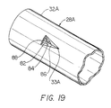
- elimination of the bearing 30 eases the assembly operation of the cap 50A, knob 46A and retainer 28A onto the shaft 16A. Since the bearing 30 has been eliminated, such that there is no longer an imposed force acting from the tang 33A to the shaft 16A, the tangs 33A are redesigned to engage the shaft in a more aggressive manner. Comparing the original tang design ( Figure 5, Figure 7) with the revised tang design ( Figure 18 and Figure 19) it can be seen that the new tang 33A includes a chevron side A 82 and a chevron side B 84 which merge at a chevron side A, B junction 86. The chevrons 82, 84 are forced sufficiently downward from the surface of the first cylindrical portion 32A of the retainer 28A, such that a definite tang opening 88 is formed between the exterior and interior surfaces of the retainer 28A.
- the retainer 28A as before includes the forward facing surface 36A, the retainer second cylindrical portion outer surface 78, and the second cylindrical portion 34A.
- the shaft 16A as before includes a shoulder 26A and a main shaft shoulder 72, but also includes tang shoulder 70, and centralizer shoulder 74.
- the centralizer shoulder 74 is of smaller outer diameter than the tang shoulder 70, the tang shoulder 70 being of smaller outer diameter than the main shaft shoulder 72.
- the outer diameters of the shoulder 74, and 70 are selected such that the retainer 28A may first be centralized relative to the shaft 16A during assembly over the shaft 16A. As the assembly progresses, the tangs 33A drag over and securely engage with the tang shoulder 70, preventing the cap from being withdrawn from the shaft.
- the tang shoulder 70 in one embodiment has an outer diameter slightly less than the adjacent main shaft shoulder 72. It should be well understood that the tang shoulder, depending on the design of the tangs, may have an outer diameter equal to, or even greater than the main shoulder 72.
- tangs are shown in Figure 18 located centrally from either end of the first cylindrical portion, they may be located toward either end of the first cylindrical portion, so as to cooperate with the tang shoulder 70.
- the second cylindrical portion outer surface 78 engages in an interference fit with the cap inner surface 76.
- the engagement force of the cap inner surface with the second cylindrical portion outer surface is designed to exceed the engagement force of the tangs with the centralizer shoulder and the tang shoulder, such that the cap remains fixed relative to the retainer when the tangs are engaged with the tang shoulder.
- the knob 46A is first inserted into openings in cap 50A, and the retainer 28A is thereafter inserted into the cap 50A.
- the retainer 28A remains fixed relative to the cap 50A, by strong interference fit, even while the tangs are dragged upwardly over the centralizer shoulder and the tang shoulder.
Landscapes
- Mechanical Pencils And Projecting And Retracting Systems Therefor, And Multi-System Writing Instruments (AREA)
Description
Claims (5)
- A writing instrument including a barrel (14) and an advance-retract mechanism actuated by rotation of a knob (46) disposed at the rear of said barrel (14) opposite a writing tip at the forward end of said instrument, a shaft (16) extending rearwardly from within said barrel (14) to receive said knob (46) for rotation of said shaft (16), said shaft (16) being effective to advance and retract said writing tip when so rotated, characterized in that a retainer (28) having a first cylindrical portion (32) and a second cylindrical portion (34) surrounds said shaft (16), in that said first cylindrical portion (32) envelopes said shaft (16) and has a plurality of rearwardly inwardly extending tangs (33) contacting the surface of said shaft (16), and in that said second cylindrical portion (34) is disposed forwardly of said first cylindrical portion (32) and has a forward facing surface (36) in spaced relation with a rearwardly facing end surface of said barrel (14).
- A writing instrument according to claim 1, characterized in that the, shaft (16) is formed of a plastics material and the retainer (28) is formed of a metallic material.
- A writing instrument according to claim 1, characterized in that the second cylindrical portion (34) includes a wall extending substantially from the forward facing surface (36) to form a forwardly facing cup.
- A writing instrument according to claim 1, characterized in that the retainer (28A) includes a second cylindrical portion outer surface (78), and in that the knob (46) has a cap (50A) with a cap inner surface (76), said second cylindrical portion outer surface (78) being engageable in an interference fit with said cap inner surface (76).
- A writing instrument according to claim 4, characterized in that the shaft (16A) includes a centralizer shoulder (74) and an adjacent tang shoulder (70) located on the distal end of the shaft (16A), and in that the engagement force of the cap inner surface (76) with the second cylindrical portion outer surface (78) exceeds the engagement force of the tangs (33A) with said centralizer shoulder (74) and said tang shoulder (70) such that said cap (50A) remains fixed relative to the retainer (28) when said tangs (33A) are engaged with said tang shoulder (70).
Applications Claiming Priority (5)
| Application Number | Priority Date | Filing Date | Title |
|---|---|---|---|
| US18776094A | 1994-01-27 | 1994-01-27 | |
| US08/358,051 US5551788A (en) | 1994-01-27 | 1994-12-16 | Writing instrument |
| US358051 | 1994-12-16 | ||
| PCT/IB1995/000094 WO1995020495A1 (en) | 1994-01-27 | 1995-01-26 | Writing instrument |
| US187760 | 2002-07-01 |
Publications (2)
| Publication Number | Publication Date |
|---|---|
| EP0740615A1 EP0740615A1 (en) | 1996-11-06 |
| EP0740615B1 true EP0740615B1 (en) | 1998-10-21 |
Family
ID=26883367
Family Applications (1)
| Application Number | Title | Priority Date | Filing Date |
|---|---|---|---|
| EP95907121A Expired - Lifetime EP0740615B1 (en) | 1994-01-27 | 1995-01-26 | Writing instrument |
Country Status (6)
| Country | Link |
|---|---|
| US (1) | US5551788A (en) |
| EP (1) | EP0740615B1 (en) |
| CA (1) | CA2181043C (en) |
| DE (1) | DE69505494T2 (en) |
| ES (1) | ES2124526T3 (en) |
| WO (1) | WO1995020495A1 (en) |
Families Citing this family (1)
| Publication number | Priority date | Publication date | Assignee | Title |
|---|---|---|---|---|
| US6764240B2 (en) | 2002-07-17 | 2004-07-20 | Bic Corporation | Universal refill mechanism and method |
Family Cites Families (6)
| Publication number | Priority date | Publication date | Assignee | Title |
|---|---|---|---|---|
| FR1004813A (en) * | 1947-05-16 | 1952-04-03 | Improvements to pen and mechanical pencils | |
| FR976412A (en) * | 1948-12-10 | 1951-03-19 | Ballpoint pen | |
| US3205864A (en) * | 1963-03-21 | 1965-09-14 | Eagle Pencil Co | Writing implement |
| US3436160A (en) * | 1966-08-08 | 1969-04-01 | Lew Mfg Co | Retractable writing instrument |
| CH483937A (en) * | 1968-12-30 | 1970-01-15 | Caran D Ache Crayons | Pen |
| US5342135A (en) * | 1993-08-17 | 1994-08-30 | The Gillette Company | Writing instrument having advance-retract mechanism |
-
1994
- 1994-12-16 US US08/358,051 patent/US5551788A/en not_active Expired - Fee Related
-
1995
- 1995-01-26 ES ES95907121T patent/ES2124526T3/en not_active Expired - Lifetime
- 1995-01-26 DE DE69505494T patent/DE69505494T2/en not_active Expired - Fee Related
- 1995-01-26 WO PCT/IB1995/000094 patent/WO1995020495A1/en not_active Ceased
- 1995-01-26 EP EP95907121A patent/EP0740615B1/en not_active Expired - Lifetime
- 1995-01-26 CA CA002181043A patent/CA2181043C/en not_active Expired - Fee Related
Also Published As
| Publication number | Publication date |
|---|---|
| DE69505494D1 (en) | 1998-11-26 |
| CA2181043A1 (en) | 1995-08-03 |
| WO1995020495A1 (en) | 1995-08-03 |
| ES2124526T3 (en) | 1999-02-01 |
| DE69505494T2 (en) | 1999-05-20 |
| US5551788A (en) | 1996-09-03 |
| EP0740615A1 (en) | 1996-11-06 |
| CA2181043C (en) | 1999-05-25 |
Similar Documents
| Publication | Publication Date | Title |
|---|---|---|
| EP0513874B1 (en) | Writing tool | |
| EP0620127B1 (en) | Stick-shaped material propelling container | |
| EP0600299B1 (en) | Writing instrument | |
| US4780016A (en) | Captive pen cap | |
| US6336761B1 (en) | Knock-type writing instrument | |
| KR100298840B1 (en) | Push-button writing instrument | |
| US5702193A (en) | Side knock type mechanical pencil | |
| US5342135A (en) | Writing instrument having advance-retract mechanism | |
| US5551788A (en) | Writing instrument | |
| US5004364A (en) | Device for advancing and retracting writing element in writing instrument | |
| US6309129B1 (en) | Writing utensils | |
| US4521126A (en) | Mechanical pencil | |
| US5171097A (en) | Mechanical pencil with lead-feeding device operable by forward shake | |
| JPH10129186A (en) | Knock-type writing instrument | |
| JP3095986B2 (en) | 2-core writing instrument | |
| JP2025125452A (en) | Retractable grip writing implement | |
| KR930003581Y1 (en) | Rotary writing instruments | |
| US4806038A (en) | Knock type mechanical pencil connection | |
| US5588764A (en) | Lock for deflectable writing utensil | |
| KR890003650Y1 (en) | Writing utensils | |
| JPH0123833Y2 (en) | ||
| JPH0528690U (en) | Compound writing instrument | |
| JP3588914B2 (en) | Cutter | |
| JPH0139590Y2 (en) | ||
| JPH0528073Y2 (en) |
Legal Events
| Date | Code | Title | Description |
|---|---|---|---|
| PUAI | Public reference made under article 153(3) epc to a published international application that has entered the european phase |
Free format text: ORIGINAL CODE: 0009012 |
|
| 17P | Request for examination filed |
Effective date: 19960821 |
|
| AK | Designated contracting states |
Kind code of ref document: A1 Designated state(s): DE ES FR GB IT |
|
| RBV | Designated contracting states (corrected) |
Designated state(s): DE ES FR GB IT |
|
| RBV | Designated contracting states (corrected) |
Designated state(s): DE ES FR GB IT |
|
| 17Q | First examination report despatched |
Effective date: 19970421 |
|
| GRAG | Despatch of communication of intention to grant |
Free format text: ORIGINAL CODE: EPIDOS AGRA |
|
| GRAG | Despatch of communication of intention to grant |
Free format text: ORIGINAL CODE: EPIDOS AGRA |
|
| GRAH | Despatch of communication of intention to grant a patent |
Free format text: ORIGINAL CODE: EPIDOS IGRA |
|
| GRAH | Despatch of communication of intention to grant a patent |
Free format text: ORIGINAL CODE: EPIDOS IGRA |
|
| GRAA | (expected) grant |
Free format text: ORIGINAL CODE: 0009210 |
|
| AK | Designated contracting states |
Kind code of ref document: B1 Designated state(s): DE ES FR GB IT |
|
| REF | Corresponds to: |
Ref document number: 69505494 Country of ref document: DE Date of ref document: 19981126 |
|
| PGFP | Annual fee paid to national office [announced via postgrant information from national office to epo] |
Ref country code: GB Payment date: 19981231 Year of fee payment: 5 Ref country code: FR Payment date: 19981231 Year of fee payment: 5 |
|
| PGFP | Annual fee paid to national office [announced via postgrant information from national office to epo] |
Ref country code: DE Payment date: 19990104 Year of fee payment: 5 |
|
| ITF | It: translation for a ep patent filed | ||
| PGFP | Annual fee paid to national office [announced via postgrant information from national office to epo] |
Ref country code: ES Payment date: 19990121 Year of fee payment: 5 |
|
| REG | Reference to a national code |
Ref country code: ES Ref legal event code: FG2A Ref document number: 2124526 Country of ref document: ES Kind code of ref document: T3 |
|
| ET | Fr: translation filed | ||
| PLBE | No opposition filed within time limit |
Free format text: ORIGINAL CODE: 0009261 |
|
| STAA | Information on the status of an ep patent application or granted ep patent |
Free format text: STATUS: NO OPPOSITION FILED WITHIN TIME LIMIT |
|
| 26N | No opposition filed | ||
| PG25 | Lapsed in a contracting state [announced via postgrant information from national office to epo] |
Ref country code: GB Free format text: LAPSE BECAUSE OF NON-PAYMENT OF DUE FEES Effective date: 20000126 |
|
| PG25 | Lapsed in a contracting state [announced via postgrant information from national office to epo] |
Ref country code: ES Free format text: LAPSE BECAUSE OF NON-PAYMENT OF DUE FEES Effective date: 20000127 |
|
| GBPC | Gb: european patent ceased through non-payment of renewal fee |
Effective date: 20000126 |
|
| PG25 | Lapsed in a contracting state [announced via postgrant information from national office to epo] |
Ref country code: FR Free format text: LAPSE BECAUSE OF NON-PAYMENT OF DUE FEES Effective date: 20000929 |
|
| PG25 | Lapsed in a contracting state [announced via postgrant information from national office to epo] |
Ref country code: DE Free format text: LAPSE BECAUSE OF NON-PAYMENT OF DUE FEES Effective date: 20001101 |
|
| REG | Reference to a national code |
Ref country code: FR Ref legal event code: ST |
|
| REG | Reference to a national code |
Ref country code: ES Ref legal event code: FD2A Effective date: 20010910 |
|
| PG25 | Lapsed in a contracting state [announced via postgrant information from national office to epo] |
Ref country code: IT Free format text: LAPSE BECAUSE OF NON-PAYMENT OF DUE FEES Effective date: 20050126 |