EP0738915B1 - Photographic printer and relative printing method - Google Patents
Photographic printer and relative printing method Download PDFInfo
- Publication number
- EP0738915B1 EP0738915B1 EP96105548A EP96105548A EP0738915B1 EP 0738915 B1 EP0738915 B1 EP 0738915B1 EP 96105548 A EP96105548 A EP 96105548A EP 96105548 A EP96105548 A EP 96105548A EP 0738915 B1 EP0738915 B1 EP 0738915B1
- Authority
- EP
- European Patent Office
- Prior art keywords
- paper
- rollers
- pair
- printing
- feeding
- Prior art date
- Legal status (The legal status is an assumption and is not a legal conclusion. Google has not performed a legal analysis and makes no representation as to the accuracy of the status listed.)
- Expired - Lifetime
Links
- 238000000034 method Methods 0.000 title claims description 10
- 238000010008 shearing Methods 0.000 claims description 15
- 238000007664 blowing Methods 0.000 claims description 6
- 238000007687 exposure technique Methods 0.000 claims 2
- 230000003287 optical effect Effects 0.000 description 6
- 238000006073 displacement reaction Methods 0.000 description 2
- 238000011144 upstream manufacturing Methods 0.000 description 2
- 230000001419 dependent effect Effects 0.000 description 1
- 238000001035 drying Methods 0.000 description 1
- 238000004519 manufacturing process Methods 0.000 description 1
Images
Classifications
-
- G—PHYSICS
- G03—PHOTOGRAPHY; CINEMATOGRAPHY; ANALOGOUS TECHNIQUES USING WAVES OTHER THAN OPTICAL WAVES; ELECTROGRAPHY; HOLOGRAPHY
- G03G—ELECTROGRAPHY; ELECTROPHOTOGRAPHY; MAGNETOGRAPHY
- G03G15/00—Apparatus for electrographic processes using a charge pattern
- G03G15/65—Apparatus which relate to the handling of copy material
- G03G15/6597—Apparatus which relate to the handling of copy material the imaging being conformed directly on the copy material, e.g. using photosensitive copy material, dielectric copy material for electrostatic printing
-
- B—PERFORMING OPERATIONS; TRANSPORTING
- B41—PRINTING; LINING MACHINES; TYPEWRITERS; STAMPS
- B41J—TYPEWRITERS; SELECTIVE PRINTING MECHANISMS, i.e. MECHANISMS PRINTING OTHERWISE THAN FROM A FORME; CORRECTION OF TYPOGRAPHICAL ERRORS
- B41J2/00—Typewriters or selective printing mechanisms characterised by the printing or marking process for which they are designed
-
- B—PERFORMING OPERATIONS; TRANSPORTING
- B41—PRINTING; LINING MACHINES; TYPEWRITERS; STAMPS
- B41J—TYPEWRITERS; SELECTIVE PRINTING MECHANISMS, i.e. MECHANISMS PRINTING OTHERWISE THAN FROM A FORME; CORRECTION OF TYPOGRAPHICAL ERRORS
- B41J2/00—Typewriters or selective printing mechanisms characterised by the printing or marking process for which they are designed
- B41J2/435—Typewriters or selective printing mechanisms characterised by the printing or marking process for which they are designed characterised by selective application of radiation to a printing material or impression-transfer material
-
- G—PHYSICS
- G03—PHOTOGRAPHY; CINEMATOGRAPHY; ANALOGOUS TECHNIQUES USING WAVES OTHER THAN OPTICAL WAVES; ELECTROGRAPHY; HOLOGRAPHY
- G03B—APPARATUS OR ARRANGEMENTS FOR TAKING PHOTOGRAPHS OR FOR PROJECTING OR VIEWING THEM; APPARATUS OR ARRANGEMENTS EMPLOYING ANALOGOUS TECHNIQUES USING WAVES OTHER THAN OPTICAL WAVES; ACCESSORIES THEREFOR
- G03B27/00—Photographic printing apparatus
- G03B27/32—Projection printing apparatus, e.g. enlarger, copying camera
- G03B27/52—Details
- G03B27/58—Baseboards, masking frames, or other holders for the sensitive material
- G03B27/587—Handling photosensitive webs
- G03B27/588—Supply rolls; Cutting arrangements
Definitions
- This invention concerns a photographic printer and the relative printing method, as set forth in the respective main claims.
- the photographic printer according to the invention is employed to print, on photosensitive paper fed from a continuous wound roll, computer images according to the so-called monoline system, whereby the printing is carried out line by line by making the paper run step-by-step below the printing device.
- the printer according to the invention can be used by itself or in combination with a normal photogram printer and is installed upstream of the developing baths and drying means.
- the printing of photographs from images created or integrated by means of a computer is more and more often used in the field of photographic printing on photosensitive paper besides the traditional optical printing from negatives.
- a reserve stock of photosensitive paper has to be created within the printer in the known printers of the monoline type, this stock being independent of the roll of paper being fed so as to prevent an uneven feed of the paper during the printing step owing to an uneven friction of the paper being moved.
- One type of printers of the state of the art fed from continuous rolls of photosensitive paper and used for monoline printing includes a pair of opposed rollers of which at least one is powered, these rollers drawing the photosensitive paper into a buffer-stock chamber along a segment which is approximately the desired segment by unrolling the roll of paper.
- This photosensitive paper is then drawn back so as to identify accurately its leading edge and is then fed forwards again by means of the pair of rollers by a length equal to the length of the photograph to be printed.
- the sheet of photosensitive paper is drawn back step by step so as to print the desired image line by line and is then again fed forwards through an opening or outlet slit so as to be fed to the operations downstream of the printing.
- the friction generated by the photosensitive paper on the feeding means, on the sidewalls of the buffer-stock chamber and on the guide elements may lead to the generation of faults on the photosensitive paper which damage the finished product.
- the purpose of this invention is to provide a photographic printer employed in monoline printing on photosensitive paper fed from a continuous wound roll, the printer ensuring an accurate feed of the photosensitive paper during the printing step and reducing considerably the length of this cycle of feeding, positioning and printing in such a way as to increase the output of the printer.
- the photosensitive paper is not subject to folds or crumpled portions which could lead to the blockage of the printer or could ruin the photosensitive paper with a resulting production of poor-quality finished products.
- the path of the photosensitive paper both during the feeding step and in the printing step is substantially free, and the causes of friction or rubbing against the elements forming the printer are considerably reduced so as to ensure the desired accuracy of feed and positioning of the photosensitive paper.
- auxiliary tension of the photosensitive paper during the printing step is precisely that generated by the paper itself and therefore can be controlled and foreseen at all times.
- the printing cycle which can be obtained with the printer according to the invention is much simpler and much shorter than that of the printers of the state of the art.
- the printer according to the invention is fed from a continuous roll of photosensitive paper and includes an assembly performing the feeding and positioning of the paper, this assembly comprising a first pair of rollers to load the paper and a second pair of rollers to draw the paper.
- At least this second pair of drawing rollers is actuated independently of the first pair of loading rollers.
- At least this second pair of drawing rollers is actuated at least momentarily with a controlled step and is capable of two-way motion.
- these two pairs of rollers define a plane of running of the paper which may be horizontal, vertical or inclined.
- this second pair of drawing rollers acts also as a means to measure the paper unrolled.
- a buffer-stock chamber is included at an intermediate position between these two pairs of rollers and can contain a segment of paper of a desired length.
- this segment of paper of a desired length is free and is subject only to the action of its own weight, which makes the paper form a loop having a substantially U-shaped conformation, thus preventing unnatural folds, crumpled portions or obstructions.
- the printer according to the invention advantageously includes supporting means which support the paper being fed during the preliminary step of loading the paper.
- These supporting means have the task of ensuring that the leading edge of the paper is gripped by the second pair of drawing rollers.
- these supporting means are stationary and are suitably shaped to accompany the paper being fed and to prevent the paper from being inserted into the buffer-stock chamber during the preliminary step of loading the paper.
- these supporting means can be momentarily actuated and have at least one first working position, in which they cooperate with the paper being fed and accompany the paper until it cooperates with the pair of drawing rollers, and a second inactive position, in which the paper is free to enter the buffer-stock chamber.
- the supporting means consist of a jet of air which can be actuated momentarily and directed suitably.
- the printer according to the invention may include switch means which have the purpose of directing the paper into the buffer-stock chamber when so required by the printing cycle.
- These switch means may be of a mechanical type and may be stationary or movable.
- the switch means are of a pneumatic type and consist, for instance, of a suitably directed jet of air or of negative pressure means.
- the printer according to the invention comprises a device for the monoline printing of the paper, sensors which monitor the leading edge of the paper and means to shear the paper.
- the printer according to the invention is associated with a programming, control and actuation assembly which governs the actuation of the pairs of rollers, the printing device and the shearing means; this programming, control and actuation assembly is associated with the sensors which monitor the position of the leading edge of the paper.
- the printer according to the invention may comprise further means to support and/or switch the paper which reduce to a minimum the friction of the paper and thus ensure a regular and accurate feed thereof.
- the printer according to the invention has a preliminary step of loading photosensitive paper from a continuous roll, this step including the following steps:
- the printer according to the invention is now ready to carry out the printing method comprising the following steps:
- the printer according to the invention includes also a sensor to monitor the tensioned paper, this monitor being positioned at an intermediate position between the two pairs of rollers so as to ensure that the paper is properly tensioned.
- auxiliary supporting means to change the direction of the paper include chute means, which can be actuated momentarily and are actuated during the printing step so as to reduce to a minimum the friction between the paper being drawn back and the auxiliary supporting and direction-changing means.
- the printer according to the invention may include not only a printing device for monoline printing but also a traditional optical printing device fitted downstream or upstream of the monoline printing device.
- the paper for the optical printing is fed forwards directly by a length equal to that of the photograph to be printed and is positioned at a position corresponding to that of the optical printing device.
- a photographic printer 10 shown in the figures is suitable both for so-called monoline digital printing and for traditional optical printing.
- the printer 10 which is described here only with reference to its characteristic elements, is fed from a continuous wound roll 11 of photosensitive paper 18 and includes an assembly 12 to feed and position paper, a monoline printing device 13 and a shearing means 14.
- the feeding and positioning assembly 12 comprises two pairs of opposed rollers, which are respectively a first pair of loading rollers 15a, 15b and a second pair of drawing rollers 16a, 16b.
- each pair of rollers 15a, 15b and 16a, 16b is associated with its own independent motor 17a, 17b.
- the pairs of rollers 15a, 15b and 16a, 16b are associated with one and the same motor and can be disconnected from each other at least momentarily by clutch means, for instance.
- the motor 17b associated with the second pair of drawing rollers 16a, 16b is of a two-way type and is suitable to draw the photosensitive paper 18 with controlled steps.
- the plane of running 19 is substantially horizontal and the buffer-stock chamber 20 is positioned below that plane 19.
- the plane of running 19 is vertical.
- the feeding and positioning assembly 12 includes, in an intermediate position between the pairs of rollers 15a, 15b and 16a, 16b and in association with the buffer-stock chamber 20, supporting means 21 which uphold the paper 18 during the loading step.
- the supporting means 21 consist of a movable platform 34 pivoted at 35 and having a first working position 34a (Figs.2a and 2b), in which the platform 34 cooperates with the moving paper 18 and prevents access to the buffer-stock chamber 20, and a second inactive position 34b, in which the platform 34 does not cooperate with the paper 18 but frees the access to the buffer-stock chamber 20.
- the supporting means 21 consist of a suitably shaped stationary element 36, which in this case is shaped as an arc of a circle, accompanies the moving paper 18 and enables the paper 18 to spread into the buffer-stock chamber 20 when the paper 18 is in the step of being drawn backwards, as shown with a line of dashes in the figure.
- the supporting means 21 consist of a suitably directed jet of air 37 generated by a blowing means 38 which can be momentarily actuated.
- the printer 10 may include switch means 22, which direct the paper 18 into the buffer-stock chamber 20 when the paper 18 is in the step of being drawn backwards.
- the switch means 22 consist of a stationary guide platform 39 positioned above the plane of running 19 of the paper 18.
- the switch means 22 comprise a vertically movable roller 23.
- the switch means 22 consist of a jet of air 32 produced by a suitably directed blowing means 33.
- the printer 10 includes the monoline printing device 13 positioned downstream of the feeding and positioning assembly 12.
- Sensors 24 are included in association with the printing device 13 and detect the presence of the leading edge of the paper 18 and set to zero a metering means 25 associated with the motor 17b of the second pair of drawing rollers 16a, 16b.
- the printer 10 includes auxiliary supporting and direction-changing means 26 consisting of rotary rollers 27 on which the photosensitive paper 18 runs.
- the rotary rollers 27 include intermediate lifting-chute elements 28, which have a first inner retracted position 28a and a second outer raised position 28b.
- the printer 10 according to the invention is governed by a the programming, control and actuation assembly 29.
- the printer 10 according to the invention includes also a traditional optical printing assembly 30.
- the loading of the paper 18 into the printer 10 according to the invention comprises the following steps:
- the printer 10 according to the invention now has (Figs.2d, 1a) the leading edge of the paper 18 coinciding with the sensors 24 and is ready to carry out the printing method by means of the monoline system comprising the following steps:
- the printer 10 includes a sensor 31 to monitor the tensioned paper at an intermediate position between the first pair of loading rollers 15a, 15b and the second pair of drawing rollers 16a, 16b, so as to ensure that the paper 18 thus fed is correctly positioned and tensioned.
- the plane of running 19 of the paper 18 in the printer 10 of Fig.3b is inclined and the step of printing is carried out on the paper 18 in a substantially vertical position.
Landscapes
- Physics & Mathematics (AREA)
- General Physics & Mathematics (AREA)
- Advancing Webs (AREA)
- Handling Of Continuous Sheets Of Paper (AREA)
- Camera Data Copying Or Recording (AREA)
Description
- This invention concerns a photographic printer and the relative printing method, as set forth in the respective main claims.
- The photographic printer according to the invention is employed to print, on photosensitive paper fed from a continuous wound roll, computer images according to the so-called monoline system, whereby the printing is carried out line by line by making the paper run step-by-step below the printing device.
- The printer according to the invention can be used by itself or in combination with a normal photogram printer and is installed upstream of the developing baths and drying means.
- The printing of photographs from images created or integrated by means of a computer is more and more often used in the field of photographic printing on photosensitive paper besides the traditional optical printing from negatives.
- Whereas in the printing from a negative the printing of the photosensitive paper is obtained in one single step with the impression of the complete image on a sheet of paper, in printing from a computer the so-called monoline printing can be employed whereby the image is printed line by line by means of a step-by-step feed of the sheet of the photosensitive paper.
- With the monoline printing system it is very important that the photosensitive paper should be fed extremely accurately so as to achieve a satisfactory result and to prevent any slipping of the photosensitive paper which could lead to the superimposing or displacement of the lines of print.
- So as to achieve this, a reserve stock of photosensitive paper has to be created within the printer in the known printers of the monoline type, this stock being independent of the roll of paper being fed so as to prevent an uneven feed of the paper during the printing step owing to an uneven friction of the paper being moved.
- One type of printers of the state of the art fed from continuous rolls of photosensitive paper and used for monoline printing includes a pair of opposed rollers of which at least one is powered, these rollers drawing the photosensitive paper into a buffer-stock chamber along a segment which is approximately the desired segment by unrolling the roll of paper.
- This photosensitive paper is then drawn back so as to identify accurately its leading edge and is then fed forwards again by means of the pair of rollers by a length equal to the length of the photograph to be printed.
- At this point the sheet of photosensitive paper is drawn back step by step so as to print the desired image line by line and is then again fed forwards through an opening or outlet slit so as to be fed to the operations downstream of the printing.
- These printers of the state of the art have shown a series of problems linked above all to the fact that the photosensitive paper is rolled up and unrolled several times without being guided into the buffer-stock chamber, thereby often generating folds or crumpled portions which make the finished product unacceptable.
- During the discharge step in these printers of the state of the art the photosensitive paper has to follow a path different from that followed during the other feeding steps, thereby requiring auxiliary guide elements which have to be actuated in this discharge step and thereby also making the printer complicated, expensive and subject to obstructions and ill-functioning.
- Moreover, the friction generated by the photosensitive paper on the feeding means, on the sidewalls of the buffer-stock chamber and on the guide elements may lead to the generation of faults on the photosensitive paper which damage the finished product.
- Furthermore, the output of these printers is very low owing to the great number of operations required for carrying out each printing cycle.
- The present applicants have designed, tested and embodied this invention to overcome the shortcomings of the state of the art and to achieve further advantages.
- This invention is set forth and characterised in the respective main claims, while the dependent claims describe variants of the idea of the main embodiment.
- The purpose of this invention is to provide a photographic printer employed in monoline printing on photosensitive paper fed from a continuous wound roll, the printer ensuring an accurate feed of the photosensitive paper during the printing step and reducing considerably the length of this cycle of feeding, positioning and printing in such a way as to increase the output of the printer.
- In the printer according to the invention the photosensitive paper is not subject to folds or crumpled portions which could lead to the blockage of the printer or could ruin the photosensitive paper with a resulting production of poor-quality finished products.
- In the printer according to the invention the path of the photosensitive paper both during the feeding step and in the printing step is substantially free, and the causes of friction or rubbing against the elements forming the printer are considerably reduced so as to ensure the desired accuracy of feed and positioning of the photosensitive paper.
- Moreover, the auxiliary tension of the photosensitive paper during the printing step is precisely that generated by the paper itself and therefore can be controlled and foreseen at all times.
- The printing cycle which can be obtained with the printer according to the invention is much simpler and much shorter than that of the printers of the state of the art.
- The printer according to the invention is fed from a continuous roll of photosensitive paper and includes an assembly performing the feeding and positioning of the paper, this assembly comprising a first pair of rollers to load the paper and a second pair of rollers to draw the paper.
- In the printer according to the invention at least this second pair of drawing rollers is actuated independently of the first pair of loading rollers.
- In the printer according to the invention at least this second pair of drawing rollers is actuated at least momentarily with a controlled step and is capable of two-way motion.
- In the printer according to the invention these two pairs of rollers define a plane of running of the paper which may be horizontal, vertical or inclined.
- According to the invention this second pair of drawing rollers acts also as a means to measure the paper unrolled.
- A buffer-stock chamber is included at an intermediate position between these two pairs of rollers and can contain a segment of paper of a desired length.
- In the buffer-stock chamber according to the invention this segment of paper of a desired length is free and is subject only to the action of its own weight, which makes the paper form a loop having a substantially U-shaped conformation, thus preventing unnatural folds, crumpled portions or obstructions.
- At this buffer-stock chamber the printer according to the invention advantageously includes supporting means which support the paper being fed during the preliminary step of loading the paper.
- These supporting means have the task of ensuring that the leading edge of the paper is gripped by the second pair of drawing rollers.
- According to a first form of embodiment these supporting means are stationary and are suitably shaped to accompany the paper being fed and to prevent the paper from being inserted into the buffer-stock chamber during the preliminary step of loading the paper.
- According to another form of embodiment these supporting means can be momentarily actuated and have at least one first working position, in which they cooperate with the paper being fed and accompany the paper until it cooperates with the pair of drawing rollers, and a second inactive position, in which the paper is free to enter the buffer-stock chamber.
- According to another variant, the supporting means consist of a jet of air which can be actuated momentarily and directed suitably.
- At a position corresponding with the supporting means and on the opposite side of the plane of running of the paper, the printer according to the invention may include switch means which have the purpose of directing the paper into the buffer-stock chamber when so required by the printing cycle.
- These switch means may be of a mechanical type and may be stationary or movable.
- According to a variant the switch means are of a pneumatic type and consist, for instance, of a suitably directed jet of air or of negative pressure means.
- Downstream of the assembly that feeds and positions the paper, the printer according to the invention comprises a device for the monoline printing of the paper, sensors which monitor the leading edge of the paper and means to shear the paper.
- The printer according to the invention is associated with a programming, control and actuation assembly which governs the actuation of the pairs of rollers, the printing device and the shearing means; this programming, control and actuation assembly is associated with the sensors which monitor the position of the leading edge of the paper.
- The printer according to the invention may comprise further means to support and/or switch the paper which reduce to a minimum the friction of the paper and thus ensure a regular and accurate feed thereof.
- The printer according to the invention has a preliminary step of loading photosensitive paper from a continuous roll, this step including the following steps:
- the feeding of the paper by a first pair of loading rollers until the leading edge of the paper cooperates with the second pair of drawing rollers , the paper cooperating advantageously with the supporting means;
- the possible halting of the supporting means when the supporting means are of a pneumatic type, or else the displacement of the supporting means to their inactive position so as to free the access to the buffer-stock chamber;
- the forward feeding of the paper by means of the first pair of loading rollers and the second pair of drawing rollers until the paper has passed beyond the shearing means by a desired pre-set segment;
- the shearing of the leading segment of paper to be eliminated.
- The printer according to the invention is now ready to carry out the printing method comprising the following steps:
- the forward feeding of the photosensitive paper by a length equal to that of the desired printing by means of the actuation of the first pair of loading rollers and of the second pair of drawing rollers;
- the clamping of the first pair of loading rollers;
- the actuation of the second pair of drawing rollers in the opposite direction by a controlled step and the simultaneous printing of the paper; the paper moves backwards and is positioned within the buffer-stock chamber so as to form, under the action of its own weight, a loop having a natural substantially U-shaped conformation;
- at the end of the printing, the forward actuation of the second pair of drawing rollers and the successive shearing of the paper, which is forwarded to the subsequent development steps.
- According to a variant the printer according to the invention includes also a sensor to monitor the tensioned paper, this monitor being positioned at an intermediate position between the two pairs of rollers so as to ensure that the paper is properly tensioned.
- According to yet another variant, auxiliary supporting means to change the direction of the paper include chute means, which can be actuated momentarily and are actuated during the printing step so as to reduce to a minimum the friction between the paper being drawn back and the auxiliary supporting and direction-changing means.
- According to a further variant, the printer according to the invention may include not only a printing device for monoline printing but also a traditional optical printing device fitted downstream or upstream of the monoline printing device.
- In this case the paper for the optical printing is fed forwards directly by a length equal to that of the photograph to be printed and is positioned at a position corresponding to that of the optical printing device.
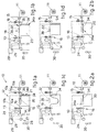
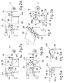
- The attached figures are given as a non-restrictive example and show some preferred embodiments of the invention as follows:-
- Figs.1a to 1d
- show diagrammatically the printing method with a photographic printer according to the invention;
- Figs.2a to 2d
- show diagrammatically the method of loading paper into the photographic printer of Fig.1;
- Figs.3a and 3b
- show diagrammatically two variants of the photographic printer of Fig.1;
- Fig.4
- is a three-dimensional view of a possible form of embodiment of the auxiliary supporting and direction-changing means;
- Figs.5a and 5b
- gives side views of the auxiliary supporting and direction-changing means in two different positions.
- In this case a
photographic printer 10 shown in the figures is suitable both for so-called monoline digital printing and for traditional optical printing. - The
printer 10 according to the invention, which is described here only with reference to its characteristic elements, is fed from a continuous wound roll 11 ofphotosensitive paper 18 and includes anassembly 12 to feed and position paper, amonoline printing device 13 and a shearing means 14. - The feeding and
positioning assembly 12 comprises two pairs of opposed rollers, which are respectively a first pair ofloading rollers 15a, 15b and a second pair of drawingrollers 16a, 16b. - In this case each pair of
rollers independent motor - According to a variant, the pairs of
rollers - The
motor 17b associated with the second pair of drawingrollers 16a, 16b is of a two-way type and is suitable to draw thephotosensitive paper 18 with controlled steps. - These two pairs of
rollers paper 18 are distanced apart in cooperation with a buffer-stock chamber 20 in which thepaper 18 can be freely arranged. - In the example of Figs.1 and 2 the plane of running 19 is substantially horizontal and the buffer-
stock chamber 20 is positioned below thatplane 19. - According to the variant shown in Fig.3b the plane of running 19 is inclined.
- According to yet another variant the plane of running 19 is vertical.
- The feeding and
positioning assembly 12 includes, in an intermediate position between the pairs ofrollers stock chamber 20, supportingmeans 21 which uphold thepaper 18 during the loading step. - In the example shown in Figs.1 and 2 the supporting means 21 consist of a
movable platform 34 pivoted at 35 and having afirst working position 34a (Figs.2a and 2b), in which theplatform 34 cooperates with the movingpaper 18 and prevents access to the buffer-stock chamber 20, and a secondinactive position 34b, in which theplatform 34 does not cooperate with thepaper 18 but frees the access to the buffer-stock chamber 20. - According to the variant shown in Fig.3a the supporting
means 21 consist of a suitably shaped stationary element 36, which in this case is shaped as an arc of a circle, accompanies the movingpaper 18 and enables thepaper 18 to spread into the buffer-stock chamber 20 when thepaper 18 is in the step of being drawn backwards, as shown with a line of dashes in the figure. - According to another variant shown in Fig.3b the supporting
means 21 consist of a suitably directed jet ofair 37 generated by a blowing means 38 which can be momentarily actuated. - In correspondence with the supporting
means 21 theprinter 10 according to the invention may include switch means 22, which direct thepaper 18 into the buffer-stock chamber 20 when thepaper 18 is in the step of being drawn backwards. - In the example shown in Figs.1a to 1d and 2a to 2d the switch means 22 consist of a
stationary guide platform 39 positioned above the plane of running 19 of thepaper 18. - According to a variant shown in Fig.3a the switch means 22 comprise a vertically
movable roller 23. - According to another variant shown in Fig.3b the switch means 22 consist of a jet of
air 32 produced by a suitably directed blowing means 33. - In this case, the
printer 10 according to the invention includes themonoline printing device 13 positioned downstream of the feeding andpositioning assembly 12. -
Sensors 24 are included in association with theprinting device 13 and detect the presence of the leading edge of thepaper 18 and set to zero a metering means 25 associated with themotor 17b of the second pair of drawingrollers 16a, 16b. - In this case the
printer 10 according to the invention includes auxiliary supporting and direction-changingmeans 26 consisting ofrotary rollers 27 on which thephotosensitive paper 18 runs. - In this example, the
rotary rollers 27 include intermediate lifting-chute elements 28, which have a first inner retractedposition 28a and a second outer raised position 28b. - When the intermediate lifting-
chute elements 28 are in their first inner retractedposition 28a, thepaper 18 is supported on the rotary rollers 27 (Fig.5a), whereas when the intermediate lifting-chute elements 28 are in their second outer raised position 28b, thepaper 18 is raised from therotary rollers 27 and slides on the intermediate lifting-chute elements 28 so as to reduce to a minimum the friction (Fig.5b). - The
printer 10 according to the invention is governed by a the programming, control andactuation assembly 29. - In this case the
printer 10 according to the invention includes also a traditionaloptical printing assembly 30. - The loading of the
paper 18 into theprinter 10 according to the invention comprises the following steps: - actuation of the pair of
loading rollers 15a, 15b (Fig.2a) and resulting forward movement of thepaper 18, which is unrolled from thewound roll 11 until its leading edge is brought into cooperation with the second pair of drawingrollers 16a, 16b (Fig.2b), the supportingplatform 34 being in thefirst working position 34a (Figs.2a, 2b), or else the blowing means 38 constituting the supportingmeans 21 being in operation (Fig.3b); - where the supporting
means 21 can be momentarily actuated, actuation of the supportingmeans 21, which in this case consist of themovable platform 34 brought to itsinactive position 34b (Fig.2c), or else the halting of the blowing means 38 constituting the supporting means 21 (Fig.3b); - actuation of the first pair of
loading rollers 15a, 15b and of the second pair of drawingrollers 16a, 16b until the leading edge of thepaper 18 has been brought beyond the shearing means 14 by a desired segment (Fig.2c); - the shearing of the leading segment of
paper 18, which is eliminated (Fig.2d). - The
printer 10 according to the invention now has (Figs.2d, 1a) the leading edge of thepaper 18 coinciding with thesensors 24 and is ready to carry out the printing method by means of the monoline system comprising the following steps: - the setting to zero of the metering means 25 associated
with the pair of drawing
rollers 16a, 16b; - the forward feeding of the
paper 18 by a length equal to that of the desired printing (Fig.1d), the speed of the first pair ofloading rollers 15a, 15b being advantageously, but not necessarily, greater than the speed of the second pair of drawingrollers 16a, 16b so as to release thepaper 18 from thewound roll 11 and to prevent possible slipping of thepaper 18 on the second pair of drawingrollers 16a, 16b; - clamping of the first pair of
loading rollers 16a, 16b; - actuation of the second pair of drawing
rollers 16a, 16b step-by-step in the opposite direction and simultaneous impression of thepaper 18 by theprinting device 13; during this step thepaper 18 thus drawn backwards cooperates with the switch means 22 and forms a loop within the buffer-stock chamber 20 (Fig.1c); - at the end of the printing, the forward actuation of the
second pair of drawing
rollers 16a, 16b and the successive shearing of thepaper 18, which is forwarded to the subsequent development steps (Fig.1d). - These operation are repeated in each printing cycle.
- According to a variant shown in Fig.3a the
printer 10 according to the invention includes asensor 31 to monitor the tensioned paper at an intermediate position between the first pair ofloading rollers 15a, 15b and the second pair of drawingrollers 16a, 16b, so as to ensure that thepaper 18 thus fed is correctly positioned and tensioned. - In this case, the plane of running 19 of the
paper 18 in theprinter 10 of Fig.3b is inclined and the step of printing is carried out on thepaper 18 in a substantially vertical position.
Claims (15)
- Photographic printer for printing on photosensitive paper according to a line-by-line exposure technique, comprising:characterised in thatmeans for supporting a roll (11) of continuous photosensitive paper (18);a line printing device (13);a feeding and positioning assembly (12) located between said supporting means and said printing device for feeding the photosensitive paper from said roll (11) and positioning the paper with respect to said printing device, said assembly (12) comprising a set of rollers (15,16) defining a plane of running (19) of the photosensitive paper (18) and arranged such that said paper may form a loop between said rollers;shearing means (14) located downstream of said printing device for cutting said paper;a control and actuation assembly (29) for controlling the actuation of said printing device, said feeding and positioning assembly and said shearing means,said feeding and positioning assembly (12) comprises a first pair of opposed rollers (15a, 15b) and a second pair of opposed rollers (16a, 16b), said second pair of rollers being actuatable independently of said first pair of rollers and capable of rotation in two opposite directions;a buffer-stock chamber (20) is provided in an intermediate position between said first and second pairs of rollers (15a, 15b, 16a, 16b);said control and actuation assembly being arranged to carry out the printing operation by clamping said first pair of rollers (15a, 15b) while rotating said second pair of rollers (16a, 16b), such that said photosensitive paper is fed backwards step-by-step into said buffer-stock chamber, and by actuating said printing device concomitantly with stepwise rotation of said second pair of rollers such that an image can printed line-by-line on said photosensitive paper being fed backwards.
- A photographic printer according to claim 2, further comprising means (21) provided in said buffer-stock chamber for supporting a leading edge of said photosensitive paper (18) at the time when said leading edge has been fed into the chamber by said first pair of rollers, such that said leading edge can be gripped by said second pair of rollers (16a, 16b) and fed toward said printing device.
- A photographic printer according to claim 2, wherein said supporting means (21) consist of a curved element (36) stationarily provided adjacently to said second pair of rollers (16a, 16b).
- A photographic printer according to claim 2, wherein said supporting means (21) consist of a platform (34) movable between a working position (34a) substantially aligned with said plane (19) of running of said photosensitive paper and an inactive position (34b).
- A photographic printer according to claim 2, wherein said supporting means (21) consist of blowing means (38) arranged to direct jet of air (37) toward said photosensitive paper.
- A photographic printer according to any preceding claim, further comprising switch means (22) located between said first and second pair of rollers for directing said photosensitive paper into said buffer-stock chamber (20) when said paper is fed backwards by said second pair of rollers during the printing operation.
- A photographic printer according to claim 6, wherein said switch means (22) consist of a stationary guide (39) located on the side of said plane of running (19) opposite to that of the buffer-stock chamber (20).
- A photographic printer according to claim 6, wherein said switch means (22) consist of an element (23) movable substantially at a right angle to the plane of running (19) and located on the side of said plane of running (19) opposite to that of said buffer-stock chamber (20).
- A photographic printer according to claim 6, wherein said switch means (22) consists of blowing means (33) arranged to direct jet of air (32) toward said photosensitive paper.
- A photographic printer according to any preceding claim, further comprising sensors (31) to monitor the tension of the paper (18).
- A photographic printer according to any preceding claim, further comprising supporting and direction-changing means (26) located downstream of said shearing means (14) and consisting of rollers (27) associated with intermediate lifting-chute elements (28) having a first inner retracted position (28a) and a second outer raised position (28b).
- A method of printing on photosensitive paper according to a line-by-line exposure technique with a photographic printer according to any of the preceding claims, comprising the steps of:preliminary loading a roll of continuous photosensitive paper in said printer such that a leading edge of the paper comes in correspondence of said shearing means (14);feeding said paper (18) forwards by a segment equal to the length of the photograph to be printed by means of the first and second pair of rollers (15a, 15b, 16a, 16b);clamping said first pair of rollers (15a, 15b);feeding backwards said paper (18) by actuating said second pair of rollers (16a, 16b) step-by-step, wherein said paper (18) re-enters said buffer-stock chamber (20) and forms therein a substantially U-shaped loop due to its own weight;actuating said printing device (13) concomitantly with said backwards stepwise rotation of said second pairs of rollers so as to print an image line-by-line on said segment of paper.
- A method of printing according to claim 12, wherein the step of preliminarily loading said roll of paper comprises the steps of:feeding the paper (18) by actuating the first pair of rollers (15a, 15b) until the leading edge of the paper (18) is brought into cooperation with the second pair of rollers (16a, 16b);supporting the leading edge of the paper during its forward movement between said first and second pair of rollers by means of supporting means (21);optionally deactivating said supporting means (21), if they are of a momentarily actuatable type, when said leading edge has been gripped by said second pair of rollers;actuating said first and second pairs of rollers (16a, 16b) for feeding the paper until the leading edge of the paper (18) has been brought beyond the shearing means (14) by a desired amount;shearing and disposing of the leading segment of paper (18) protruding beyond the shearing means.
- A method of printing according to claims 12 or 13, further comprising the step of actuating said switching means (22) at the beginning of the step of backwards feeding of the paper (18) to direct said paper into said buffer-stock chamber (20).
- A method of printing according to claims 12 to 14, further comprising the step of bringing at the beginning of the step of backwards feeding the paper (18) said intermediate lifting-chute elements (28) associated with said rollers (27) of the supporting and direction-changing means (26) in their second outer raised position (28b) so as to release the paper (18) from the rollers (27).
Applications Claiming Priority (2)
| Application Number | Priority Date | Filing Date | Title |
|---|---|---|---|
| ITUD950074 | 1995-04-19 | ||
| IT95UD000074A IT1280161B1 (en) | 1995-04-19 | 1995-04-19 | PHOTOGRAPHIC PRINTER AND RELATED PRINTING PROCEDURE |
Publications (3)
| Publication Number | Publication Date |
|---|---|
| EP0738915A2 EP0738915A2 (en) | 1996-10-23 |
| EP0738915A3 EP0738915A3 (en) | 1997-04-02 |
| EP0738915B1 true EP0738915B1 (en) | 2001-11-14 |
Family
ID=11421816
Family Applications (1)
| Application Number | Title | Priority Date | Filing Date |
|---|---|---|---|
| EP96105548A Expired - Lifetime EP0738915B1 (en) | 1995-04-19 | 1996-04-09 | Photographic printer and relative printing method |
Country Status (4)
| Country | Link |
|---|---|
| US (1) | US5706078A (en) |
| EP (1) | EP0738915B1 (en) |
| DE (1) | DE69616862T2 (en) |
| IT (1) | IT1280161B1 (en) |
Families Citing this family (4)
| Publication number | Priority date | Publication date | Assignee | Title |
|---|---|---|---|---|
| US6227731B1 (en) | 1999-10-14 | 2001-05-08 | Eastman Kodak Company | Printing apparatus |
| JP2003072054A (en) * | 2001-09-04 | 2003-03-12 | Seiko Epson Corp | INK TYPE RECORDING APPARATUS AND CLEANING CONTROL METHOD THEREOF |
| JP3994804B2 (en) * | 2002-06-25 | 2007-10-24 | ブラザー工業株式会社 | Tape printer and tape cassette |
| JP5148363B2 (en) * | 2008-05-13 | 2013-02-20 | 富士フイルム株式会社 | Image forming apparatus and maintenance method |
Family Cites Families (12)
| Publication number | Priority date | Publication date | Assignee | Title |
|---|---|---|---|---|
| US3818493A (en) * | 1972-05-22 | 1974-06-18 | Dyk Res Corp Van | High speed xerographic printer |
| US4234261A (en) * | 1977-04-04 | 1980-11-18 | Mannesmann Aktiengesellschaft | Printer |
| US4147427A (en) * | 1978-02-24 | 1979-04-03 | Pako Corporation | Variable working distance photographic printer with stationary paper magazines |
| JPS57115542A (en) * | 1981-01-09 | 1982-07-19 | Copal Co Ltd | Loop control device for picture printer |
| JP2529348B2 (en) * | 1988-04-27 | 1996-08-28 | 富士写真フイルム株式会社 | Image synthesis printer |
| JP2573877B2 (en) * | 1989-08-02 | 1997-01-22 | グラフテック株式会社 | Printing method |
| JP2915619B2 (en) * | 1991-05-13 | 1999-07-05 | 富士写真フイルム株式会社 | Paper magazine mounting device and method |
| JP2889736B2 (en) * | 1991-05-24 | 1999-05-10 | 富士写真フイルム株式会社 | Paper transport device for photo printer |
| JP2974222B2 (en) * | 1991-12-03 | 1999-11-10 | 富士写真フイルム株式会社 | Photographic printing apparatus and control method thereof |
| JP3171714B2 (en) * | 1993-01-19 | 2001-06-04 | 富士写真フイルム株式会社 | Guide holding structure for image recording material |
| JP2822832B2 (en) * | 1993-02-17 | 1998-11-11 | ノーリツ鋼機株式会社 | Photo printing equipment |
| JP2906902B2 (en) * | 1993-03-10 | 1999-06-21 | ノーリツ鋼機株式会社 | Image printing method and apparatus |
-
1995
- 1995-04-19 IT IT95UD000074A patent/IT1280161B1/en active IP Right Grant
-
1996
- 1996-04-09 EP EP96105548A patent/EP0738915B1/en not_active Expired - Lifetime
- 1996-04-09 DE DE69616862T patent/DE69616862T2/en not_active Expired - Fee Related
- 1996-04-10 US US08/629,881 patent/US5706078A/en not_active Expired - Fee Related
Also Published As
| Publication number | Publication date |
|---|---|
| EP0738915A2 (en) | 1996-10-23 |
| DE69616862T2 (en) | 2002-08-14 |
| US5706078A (en) | 1998-01-06 |
| ITUD950074A0 (en) | 1995-04-19 |
| ITUD950074A1 (en) | 1996-10-19 |
| EP0738915A3 (en) | 1997-04-02 |
| IT1280161B1 (en) | 1998-01-05 |
| DE69616862D1 (en) | 2001-12-20 |
Similar Documents
| Publication | Publication Date | Title |
|---|---|---|
| US5394215A (en) | Photographic processing apparatus | |
| EP0420297B1 (en) | Processing paper and other webs | |
| US4129238A (en) | Apparatus for feeding a web in registry between web passes through a processing machine | |
| JP2915619B2 (en) | Paper magazine mounting device and method | |
| DE69528404T2 (en) | Photographic material feeder | |
| KR910003002B1 (en) | Method and apparatus for intermittently treating continuous constant length of continuous flexible web | |
| JP2013123832A (en) | Digital printing method and digital printing apparatus | |
| US3951023A (en) | Transport guide for pliable sheet material | |
| US4874161A (en) | Sheet transporting apparatus | |
| US5706078A (en) | Photographic printer and method for monoline printing | |
| CA1138523A (en) | Copier scan and collator back bar control | |
| US3911771A (en) | Transport and shearing apparatus | |
| US4963896A (en) | Recording media transporting device with arcshaped path | |
| JPS6359138B2 (en) | ||
| JP3144219B2 (en) | Photo processing equipment | |
| US7007602B2 (en) | Method and apparatus for controlling a cutting position of a web member and device therefor | |
| US5735474A (en) | Method for forwarding and rewinding photosensitive material | |
| JPH0431071A (en) | Printing device | |
| JP2979957B2 (en) | Disconnecting a reader in a photo processing device | |
| US6520078B1 (en) | Stencil printing machine | |
| JPH08216363A (en) | Web transfer device for automatic paper transfer device | |
| US20200062527A1 (en) | Conveying apparatus | |
| JPH079149Y2 (en) | Paper transport device for photo printing printers | |
| US20250276867A1 (en) | Rolling machine for printed substrates and related control method | |
| JPS5927891B2 (en) | photo printing equipment |
Legal Events
| Date | Code | Title | Description |
|---|---|---|---|
| PUAI | Public reference made under article 153(3) epc to a published international application that has entered the european phase |
Free format text: ORIGINAL CODE: 0009012 |
|
| AK | Designated contracting states |
Kind code of ref document: A2 Designated state(s): DE ES FR GB IT |
|
| PUAL | Search report despatched |
Free format text: ORIGINAL CODE: 0009013 |
|
| AK | Designated contracting states |
Kind code of ref document: A3 Designated state(s): DE ES FR GB IT |
|
| 17P | Request for examination filed |
Effective date: 19970627 |
|
| GRAG | Despatch of communication of intention to grant |
Free format text: ORIGINAL CODE: EPIDOS AGRA |
|
| 17Q | First examination report despatched |
Effective date: 20010117 |
|
| GRAG | Despatch of communication of intention to grant |
Free format text: ORIGINAL CODE: EPIDOS AGRA |
|
| GRAH | Despatch of communication of intention to grant a patent |
Free format text: ORIGINAL CODE: EPIDOS IGRA |
|
| GRAH | Despatch of communication of intention to grant a patent |
Free format text: ORIGINAL CODE: EPIDOS IGRA |
|
| GRAA | (expected) grant |
Free format text: ORIGINAL CODE: 0009210 |
|
| AK | Designated contracting states |
Kind code of ref document: B1 Designated state(s): DE ES FR GB IT |
|
| REF | Corresponds to: |
Ref document number: 69616862 Country of ref document: DE Date of ref document: 20011220 |
|
| REG | Reference to a national code |
Ref country code: GB Ref legal event code: IF02 |
|
| ET | Fr: translation filed | ||
| PG25 | Lapsed in a contracting state [announced via postgrant information from national office to epo] |
Ref country code: ES Free format text: LAPSE BECAUSE OF FAILURE TO SUBMIT A TRANSLATION OF THE DESCRIPTION OR TO PAY THE FEE WITHIN THE PRESCRIBED TIME-LIMIT Effective date: 20020530 |
|
| RAP2 | Party data changed (patent owner data changed or rights of a patent transferred) |
Owner name: IMIP LLC |
|
| PLBE | No opposition filed within time limit |
Free format text: ORIGINAL CODE: 0009261 |
|
| STAA | Information on the status of an ep patent application or granted ep patent |
Free format text: STATUS: NO OPPOSITION FILED WITHIN TIME LIMIT |
|
| 26N | No opposition filed | ||
| PG25 | Lapsed in a contracting state [announced via postgrant information from national office to epo] |
Ref country code: IT Free format text: LAPSE BECAUSE OF NON-PAYMENT OF DUE FEES;WARNING: LAPSES OF ITALIAN PATENTS WITH EFFECTIVE DATE BEFORE 2007 MAY HAVE OCCURRED AT ANY TIME BEFORE 2007. THE CORRECT EFFECTIVE DATE MAY BE DIFFERENT FROM THE ONE RECORDED. Effective date: 20050409 |
|
| PGFP | Annual fee paid to national office [announced via postgrant information from national office to epo] |
Ref country code: GB Payment date: 20050411 Year of fee payment: 10 |
|
| PGFP | Annual fee paid to national office [announced via postgrant information from national office to epo] |
Ref country code: DE Payment date: 20050422 Year of fee payment: 10 |
|
| PGFP | Annual fee paid to national office [announced via postgrant information from national office to epo] |
Ref country code: FR Payment date: 20050425 Year of fee payment: 10 |
|
| PG25 | Lapsed in a contracting state [announced via postgrant information from national office to epo] |
Ref country code: GB Free format text: LAPSE BECAUSE OF NON-PAYMENT OF DUE FEES Effective date: 20060409 |
|
| PG25 | Lapsed in a contracting state [announced via postgrant information from national office to epo] |
Ref country code: DE Free format text: LAPSE BECAUSE OF NON-PAYMENT OF DUE FEES Effective date: 20061101 |
|
| GBPC | Gb: european patent ceased through non-payment of renewal fee |
Effective date: 20060409 |
|
| REG | Reference to a national code |
Ref country code: FR Ref legal event code: ST Effective date: 20061230 |
|
| PG25 | Lapsed in a contracting state [announced via postgrant information from national office to epo] |
Ref country code: FR Free format text: LAPSE BECAUSE OF NON-PAYMENT OF DUE FEES Effective date: 20060502 |