EP0738873B1 - Gyroscope à fibre optique multi-axe - Google Patents
Gyroscope à fibre optique multi-axe Download PDFInfo
- Publication number
- EP0738873B1 EP0738873B1 EP96400816A EP96400816A EP0738873B1 EP 0738873 B1 EP0738873 B1 EP 0738873B1 EP 96400816 A EP96400816 A EP 96400816A EP 96400816 A EP96400816 A EP 96400816A EP 0738873 B1 EP0738873 B1 EP 0738873B1
- Authority
- EP
- European Patent Office
- Prior art keywords
- interferometers
- modulation
- phase
- equal
- photodetector
- Prior art date
- Legal status (The legal status is an assumption and is not a legal conclusion. Google has not performed a legal analysis and makes no representation as to the accuracy of the status listed.)
- Expired - Lifetime
Links
- 239000013307 optical fiber Substances 0.000 title claims description 5
- 230000010363 phase shift Effects 0.000 claims description 56
- 238000005259 measurement Methods 0.000 claims description 37
- 238000000034 method Methods 0.000 claims description 36
- 238000012545 processing Methods 0.000 claims description 36
- 239000000835 fiber Substances 0.000 claims description 19
- 230000003287 optical effect Effects 0.000 claims description 19
- 230000008569 process Effects 0.000 claims description 15
- 230000000694 effects Effects 0.000 claims description 14
- 230000001902 propagating effect Effects 0.000 claims description 11
- 230000010355 oscillation Effects 0.000 claims description 10
- 230000000737 periodic effect Effects 0.000 claims description 8
- 230000008033 biological extinction Effects 0.000 claims description 7
- 230000008859 change Effects 0.000 claims description 7
- 238000005215 recombination Methods 0.000 claims description 6
- 230000006798 recombination Effects 0.000 claims description 6
- 238000005070 sampling Methods 0.000 claims description 6
- 238000006243 chemical reaction Methods 0.000 claims description 4
- 238000000926 separation method Methods 0.000 claims description 4
- 244000045947 parasite Species 0.000 claims description 3
- 230000002123 temporal effect Effects 0.000 description 22
- 238000010586 diagram Methods 0.000 description 6
- 230000035945 sensitivity Effects 0.000 description 6
- 230000004044 response Effects 0.000 description 5
- 230000003071 parasitic effect Effects 0.000 description 4
- 230000010287 polarization Effects 0.000 description 4
- 238000012937 correction Methods 0.000 description 3
- 230000007423 decrease Effects 0.000 description 3
- 238000013519 translation Methods 0.000 description 3
- 230000014616 translation Effects 0.000 description 3
- 230000000996 additive effect Effects 0.000 description 2
- 230000002238 attenuated effect Effects 0.000 description 2
- 238000013461 design Methods 0.000 description 2
- 238000004519 manufacturing process Methods 0.000 description 2
- 229910052761 rare earth metal Inorganic materials 0.000 description 2
- 150000002910 rare earth metals Chemical class 0.000 description 2
- 230000006641 stabilisation Effects 0.000 description 2
- 238000011105 stabilization Methods 0.000 description 2
- 229910052691 Erbium Inorganic materials 0.000 description 1
- 229910052779 Neodymium Inorganic materials 0.000 description 1
- 230000009471 action Effects 0.000 description 1
- 239000000654 additive Substances 0.000 description 1
- 238000013459 approach Methods 0.000 description 1
- 230000000712 assembly Effects 0.000 description 1
- 238000000429 assembly Methods 0.000 description 1
- 230000008901 benefit Effects 0.000 description 1
- 239000003638 chemical reducing agent Substances 0.000 description 1
- 230000007547 defect Effects 0.000 description 1
- 230000001419 dependent effect Effects 0.000 description 1
- 238000001514 detection method Methods 0.000 description 1
- 238000005265 energy consumption Methods 0.000 description 1
- 238000005516 engineering process Methods 0.000 description 1
- UYAHIZSMUZPPFV-UHFFFAOYSA-N erbium Chemical compound [Er] UYAHIZSMUZPPFV-UHFFFAOYSA-N 0.000 description 1
- 230000003993 interaction Effects 0.000 description 1
- 239000011159 matrix material Substances 0.000 description 1
- 238000000691 measurement method Methods 0.000 description 1
- QEFYFXOXNSNQGX-UHFFFAOYSA-N neodymium atom Chemical compound [Nd] QEFYFXOXNSNQGX-UHFFFAOYSA-N 0.000 description 1
- -1 neodymium or erbium Chemical class 0.000 description 1
- 230000001151 other effect Effects 0.000 description 1
- 238000005192 partition Methods 0.000 description 1
- 238000005498 polishing Methods 0.000 description 1
- 238000011176 pooling Methods 0.000 description 1
- 230000005855 radiation Effects 0.000 description 1
- 238000000638 solvent extraction Methods 0.000 description 1
- 230000001360 synchronised effect Effects 0.000 description 1
- 230000007704 transition Effects 0.000 description 1
Images


Classifications
-
- G—PHYSICS
- G01—MEASURING; TESTING
- G01C—MEASURING DISTANCES, LEVELS OR BEARINGS; SURVEYING; NAVIGATION; GYROSCOPIC INSTRUMENTS; PHOTOGRAMMETRY OR VIDEOGRAMMETRY
- G01C19/00—Gyroscopes; Turn-sensitive devices using vibrating masses; Turn-sensitive devices without moving masses; Measuring angular rate using gyroscopic effects
- G01C19/58—Turn-sensitive devices without moving masses
- G01C19/64—Gyrometers using the Sagnac effect, i.e. rotation-induced shifts between counter-rotating electromagnetic beams
- G01C19/72—Gyrometers using the Sagnac effect, i.e. rotation-induced shifts between counter-rotating electromagnetic beams with counter-rotating light beams in a passive ring, e.g. fibre laser gyrometers
- G01C19/728—Assemblies for measuring along different axes, e.g. triads
Definitions
- the invention relates to a method for measurement of rotational speeds with respect to several axes, as well as an interferometric fiber gyroscope optics implementing this method.
- Navigation, guidance or stabilization generally use multiple axes of rotation measurement: two orthogonal axes in the case stabilization of a line of sight, three axes orthogonal in the case of navigation and guidance, four and more when redundancy is sought. Three axes are necessary to measure the position angle of a mobile.
- Such systems can use independent optical gyroscopes each comprising a source and a receiver. These devices are well known and just place several to make possible the desired measures.
- multi-axis gyroscopes For cost reasons, compactness and reliability, it is interesting to reduce the number of components. To do this, several elements can be shared between the means of measurement along different axes. Many gyroscopes for measuring rotational speed compared to several axes called “multi-axis gyroscopes" have thus been proposed. These gyroscopes include Sagnac ring interferometers for each direction of measurement, but can use the same light source, the same photodetector or the same electronic processing unit.
- a separating blade or other separating device splits a wave incident.
- the two counterpropagative waves as well created propagate in opposite directions, along a path closed optics, recombine and produce interferences which depend on the phase difference between the waves during their recombination.
- the closed optical path of the interferometers de Sagnac was defined by mirrors. It is maintained known that it can be constituted by a multi-turn coil of single mode optical fiber.
- Measuring the relative phase difference allows to quantify the phenomenon which generated it.
- the main physical phenomenon likely to create these non-reciprocal disturbances is the Sagnac effect produced by the rotation of the interferometer with respect to to an axis perpendicular to the plane of its optical path closed.
- the Faraday effect or magneto-optical effect collinear is also known to produce such non-reciprocal effects.
- Other effects can under certain conditions also produce a non-reciprocal phase difference.
- variations of many parameters representative of the environment which are often the cause of disruption of measurements, only have effects reciprocals on the Sagnac interferometer, do not disturb the relative phase difference between counterpropagative waves and therefore have no influence on the measurement of the parameter studied. Such is the case of slow variations in temperature, index, etc ..., which modify the optical path traveled by waves, but modify it reciprocally.
- phase difference ⁇ m typically has the amplitude ⁇ / 2.
- a phase modulator is usually placed at one end of the multi-turn coil of the interferometer and controlled by a signal V m .
- the controlled phase difference ⁇ c is produced by the phase modulator controlled by a signal V c .
- the modulation phase shift ⁇ c has a feedback component ⁇ cr . It therefore also includes a bias component ⁇ m with a period equal to the modulation period T m .
- This biasing component ⁇ m is generally itself the sum of an oscillation term ⁇ o and a constant offset term ⁇ d , the value of the oscillation term ⁇ o at an instant t being opposite to that at time t + T m / 2.
- a single light source is used. he this is, in fact, one of the most expensive elements, as well as the one consuming the most energy.
- the light emitted by this source can then be shared permanently with, for example, separators of bundles or couplers.
- separators of bundles or couplers We are talking about a "source sharing".
- At each interferometer, are usually associated with a detector and a unit signal processing electronics.
- Source sharing is done, for example, by a 3 x 3 fiber coupler including one of the three arms input is connected to the common source.
- Each of the output arm of the 3 x 3 coupler is connected to one of the three interferometers via a coupler 2 x 2 fiber, the second coupler input arm 2 x 2 being connected to a detector.
- the photodetector is connected to a first interferometer from which it receives a signal, while the source is connected to a second interferometer to which it sends light.
- the switches connect the photodetector to the second interferometer while the source is connected to the third, so that the photodetector receives the signal previously sent by the source in the second interferometer, while the source is sending light into the third interferometer.
- the photodetector is connected to the third interferometer, while the source is connected to the first.
- the signal received by the photodetector therefore corresponds successively to each of the three interferometers during a time interval equal to ⁇ . This succession is combined with a modulation of bias on period 6 ⁇ on the three interferometers.
- the time multiplexing of the three signals is does so by switching.
- FR-2,605,101 describes another gyroscope tri-axis exploiting source sharing and multiplexing.
- the three spools of fibers are there coupled in series and connected to each other by their middle.
- ⁇ the transit time of a wave in any of the interferometers
- a signal sent to the first coil at time t does not arrives at the second that at the moment t + ⁇ and at the third at time t + 2 ⁇ .
- the photodetector therefore receives the information in origin of the three interferometers, respectively at times t + ⁇ , t + 2 ⁇ and t + 3 ⁇ .
- the source must therefore send a signal at a rate of at least 3 ⁇ , so that the output signals are not mixed.
- this multiplexing is combined with a bias modulation of period 6 ⁇ , applied by modulators to the three interferometers.
- This device has the disadvantage of giving relatively low return powers due to losses in the couplers connecting the interferometers.
- place in the same case, so orthogonal, three coils connected together by couplers, is not technically easy.
- the fibers of connection to the coils also make the device sensitive to temperature gradient.
- the source is linked to a distribution element optic comprising several branches, each of these branches leading to the two ends of one of interferometers through a divider of beam.
- Phase modulators placed at level beam splitters, apply differences phase to counterpropagative waves traveling through interferometers.
- the multiplexing process used with this device consists of alternately starting up, for each of the interferometers, a signal of modulation while maintaining a zero signal for the whole other interferometers.
- This device is used with a method of alternating multiplexing, for each interferometer, a measurement modulation with extinction modulation.
- the latter is obtained by applying modulation amplitude phase ⁇ because it corresponds to a phase opposition of the counterpropagative waves in interferometer output, generating power nothing. Only one of the interferometers at a time is submitted to a measurement modulation.
- the return power received by the photodetector fluctuates over time, even if the powers from the interferometers are balanced by the mounting the gyroscope. This is due to the fact that differences of 10 to 20% are always present between the different axes, these differences being amplified during the demodulation of received signals.
- the photodetector being followed by a peak reducer and of an amplifier, the power jumps generated may saturate the amplifier.
- the device described in the previous patent is penalized by the fact that couplers used cause significant losses energy, the power received by the photodetector being very weak compared to that emitted by the source.
- the object of the present invention is a method for measuring rotational speeds with respect to multiple axes, reliable, precise and easy to implement artwork.
- the object of the present invention is therefore to multi-axis interferometric gyroscope admitting a single light source and allowing multiplexing temporal signals with the use of a photodetector and a processing unit common electronics, without requiring switch.
- Another objective of the invention is to achieve an inexpensive, compact, reliable and affordable multi-axis gyroscope low energy consumption.
- the invention aims to be able to perform closed-loop processing while retaining perfect stability.
- the signals emitted by the source reach all the interferometers I i , then the photodetector, substantially simultaneously.
- the controlled modulation phase differences ⁇ c, i generated by the modulators include biasing components ⁇ m, i of common modulation period T m substantially equal to double 2 ⁇ of the common transit time.
- ⁇ , and of common amplitude equal to a phase bias not multiple of ⁇ , the value of each biasing component ⁇ m, i at an instant t being opposite to that of the component at the instant t + T m / 2, each half-period T m / 2 being divided into at least N time intervals ⁇ t i .
- a signal arriving at the processing unit is affected simultaneously by Sagnac phase shifts ⁇ s, i representative of the rotational speeds of all the interferometers I i , adding to the modulation phase differences ⁇ c, i , the Sagnac phase shifts ⁇ s, i being extracted by the processing unit by sampling the signal over the N time intervals ⁇ t i .
- the modulation applied to each interferometer is thus a modulation similar to that applied in a gyroscope with a single measurement axis.
- the bias modulations are identical for the set of gyroscope interferometers according to the invention, but translated over time.
- An electronic demultiplexing and demodulation circuit placed at the output of the photodetector makes it possible to extract the signals from the various interferometers I i .
- An advantage of this multiplexing mode is that the power received by the photodetector from the interferometers I i is invariant.
- signals D i demultiplexing and demodulation periods equal to the common modulation period T m , such that the demultiplexing and demodulation signal D i associated with each of the interferometers I i is equal to 1 over the time interval ⁇ t i of corresponding sign change, 0 of the interval ⁇ t i + 1 following to (N-2 ) th interval ⁇ t N + i-2 next, 1 on the (N-1) th interval ⁇ t N + i-1 next, -1 on the N th interval ⁇ t N + i next, 0 of the (N + 1) th ⁇ t N + i + 1 at (2N-2) th ⁇ t 2N + i-2 following intervals, and -1 on the (2N-1) th interval ⁇ t 2N + i-1 following interval.
- the phase difference of controlled modulation ⁇ c, i generated in each interferometer I i is produced by the modulators by simultaneously applying the same phase shift of controlled modulation ⁇ c, i to the two contrapropagative waves propagating in l interferometer I i .
- These counterpropagative waves recombine after a time shift equal to the transit time ⁇ , the phase shift ⁇ c, i determining the phase difference ⁇ c, i .
- the modulation phase shift ⁇ c, i has a bias component ⁇ m, i with a period equal to the modulation period T m , the bias component ⁇ m, i being the sum of an oscillation term ⁇ o, i and a constant shift term ⁇ d, i .
- the value of the oscillation term ⁇ o, i at an instant t is opposite to that at the instant t + T m / 2, the oscillation term ⁇ o, i having an amplitude equal to half of the phase bias , and changing sign at the start of the time interval ⁇ t i corresponding to the interferometer I i .
- the phase bias is equal to ⁇ / 2.
- This value makes it possible to obtain a maximum sensitivity of the signal measured in the presence of a phase shift produced by rotations of interferometers.
- the time intervals ⁇ t i defined in the measurement method according to the invention are advantageously equal and are equal to 1 / N of the modulation period T m / 2.
- This distribution of time facilitates in particular the attenuation of parasitic effects due to overlapping responses during the transitions between the successive time intervals ⁇ t i .
- Such undesirable effects are mainly due to differences between the respective transit times in the different interferometers.
- a periodic signal processing gate is applied to an output signal reaching the processing unit.
- the gate consists of an amplitude modulation with a gate period equal to 1 / (2N) of the modulation period T m , leaving the signal unchanged during part of each gate period centered on one of the time intervals ⁇ t i , and canceling it during the other part of the period.
- the parasitic effects due to differences between the modulation half-period T m / 2 and the natural periods ⁇ i of the interferometers I i are thus attenuated.
- a second correction means action is taken on a signal emitted by the source by an electronic modulation circuit connected to the source.
- This arrangement applies a sequential extinction to the signal at an extinction period equal to 1 / (2N) of the modulation period T m .
- the parasitic effects due to differences between the modulation half-period T m / 2 and the natural periods ⁇ i of the interferometers I i are thus attenuated.
- This sequential extinction is advantageously achieved by mounting modulation electronics that keep a low noise level.
- a possible Sagnac phase shift ⁇ s, i is compensated for by a rotation of the interferometer I i and adding to the biasing component ⁇ m, i of the phase difference of controlled modulation ⁇ c, i associated, by a feedback component ⁇ cr, i of the phase difference of modulation ⁇ c, i .
- the sum ⁇ s, i + ⁇ cr, i of the Sagnac phase shift ⁇ s, i and of the feedback component ⁇ cr, i is constantly slaved to zero, so that the rotations of the interferometers I i are deduced from the components of feedback ⁇ cr, i .
- the controlled modulation phase differences ⁇ c, i generated by the modulators include bias components ⁇ m, i of common modulation period T m substantially equal to double 2 ⁇ of the common transit time ⁇ and of common amplitude equal to a phase bias not multiple of ⁇ , the value of each biasing component ⁇ m, i at a time t being opposite to that of the component at time t + T m / 2 .
- each half-period T m / 2 being divided into at least N time intervals ⁇ t i , the modulator of each interferometer I i produces a change in sign of the biasing component ⁇ m, i associated, at the start of a and of only one of the time intervals ⁇ t i .
- a signal arriving at the processing unit is affected simultaneously by Sagnac phase shifts ⁇ s, i representative of the rotational speeds of all the interferometers I i and adding to the modulation phase differences ⁇ c, i .
- These phase shifts Sagnac ⁇ s, i are extracted by the processing unit by sampling the signal over the N time intervals ⁇ t i .
- the gyroscope comprises a set of couplers connecting the source, the photodetector and the interferometers I i .
- the set of couplers has N entry doors and N exit doors, one entry door being connected to the source and N - 1 entry doors to the photodetector, and the N exit doors being connected, respectively, to the interferometers I i .
- a signal from the source is divided into N signals which arrive in a way substantially simultaneous to all of the interferometers and which, after passing through these last, arrive approximately simultaneous to the photodetector because the durations of transit are approximately the same for all interferometers.
- this device makes it possible, not only reception of the same light output by each of the interferometers, coming from the source, but also reception by the photodetector of the same light output from each of interferometers.
- phase modulators makes multiplexing possible without presenting complexity from the use of optical switches.
- the gyroscope includes a single coupler comprising N entry doors and N exit doors.
- the couplers each have two entry doors and two doors and form a tree-like whole.
- polarization maintaining couplers for example made by lateral polishing of a fiber, with a light source emitting polarized light, such as a superluminescent diode (DSL).
- DSL superluminescent diode
- the gyroscope includes two interferometers and a coupler, this coupler 1/2, 1/2 sharing an incident power on a first front door connected to the source, in two powers transmitted respectively to the two gates of output connected to two equal interferometers each at half the incident power.
- the two interferometers each receive the same light output and signals from the interferometers and received by the photodetector are balanced.
- the gyroscope includes three interferometers and two couplers.
- a first of these couplers has two entry doors, respectively connected to the source and the photodetector, a door output connected to a first of the interferometers and another exit door connected to a first second coupler entrance door.
- the second coupler 1/2, 1/2 has a second entrance door connected to the photodetector and exit doors, respectively to the other two interferometers.
- the first coupler 1/3, 2/3 shares incident power on the door input connected to the source in a first power transmitted to the exit door connected to the first interferometer, equal to a third of the power incident, and in a second power transmitted to the exit door connected to the first entry door of the second coupler, equal to two thirds of the incident power.
- the three interferometers each receive the same light output and signals from the interferometers and received by the photodetector are balanced.
- the optical path between an interferometer and a coupler being greater than the coherence length of the source, the waves coming from the different interferometers are non-consistent and cannot interfere.
- Polarizers are advantageously interposed between the couplers and the interferometers I i .
- the gyroscope according to the invention is usefully coupled with other gyroscopes.
- Figure 1 is a representation of a tri-axis gyroscope according to the invention.
- Figure 2 shows the changes effects of an applied bias shift phase shift according to the method of the invention in a first Figure 1 gyroscope interferometer, of the same shifted phase shift of the transit time, and the bias phase difference generated.
- Figure 3 represents the time evolution of the phase difference of Figure 2, the variation of interference power as a function of this phase difference and the time course of this power.
- Figure 4 represents the time evolution of the phase difference of Figures 2 and 3, modified by a Sagnac phase shift, the variation in power interference as a function of phase difference obtained and the time evolution of this power.
- Figure 5 shows the changes temporal, according to the method of the invention, bias shifts applied in each of the three interferometers of the gyroscope of Figure 1.
- Figure 6 shows the changes temporal, according to this first mode of multiplexing, interference powers obtained in each of three interferometers of Figure 1 in rotation, as well than the power received by the photodetector.
- Figure 7 is a block diagram of the circuit demultiplexing and demodulation corresponding to the tri-axis gyroscope of Figure 1 and the multiplexing of Figure 5.
- Figure 8 shows the changes of the three demultiplexing signals and demodulation applied in the circuit of Figure 7.
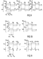
- Figure 9 shows, for each of the three Figure 1 interferometers, the phase difference bias applied and the signal demultiplexing and corresponding demodulation.
- Figure 10 shows the phase differences biasing according to the method of the invention in correspondence with demultiplexing signals and demodulation for a bi-axis gyroscope.
- Figure 11 shows the phase differences biasing according to the method of the invention in correspondence with demultiplexing signals and demodulation, for a gyroscope with N axes of measured.
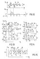
- Figure 12 shows the changes times of an applied feedback phase shift in an interferometer, of the same phase shift translated from the transit time and the phase difference of generated feedback.
- Figure 13 represents the evolutions effects of an applied bias shift phase shift in an interferometer, its translated from the duration of transit, of the bias phase difference and the interference power, when the modulation period is a little longer transit time.
- Figure 14 shows the changes interference power in the case asymmetric modulation, when the period of modulation is respectively greater than double of transit time, equal and less.
- Figure 15 represents the time evolution interference power in the case of a asymmetric modulation with a modulation period greater than double the transit time, in presence of a synchronous door.
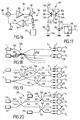
- Figure 16 is a block diagram of a modular light source with low noise.
- Figure 17 is a diagram of a mirror current and modulated source of the assembly shown in Figure 16.
- Figure 18 shows a second mode of production of a multi-axis gyroscope according to the invention.
- Figure 19 shows a third mode of production of a multi-axis gyroscope according to the invention, comprising four measurement axes.
- Figure 20 is a diagram of a gyroscope with four measurement axes, combining two gyroscopes with two axes according to the invention.
- the interferometric gyroscope with three measurement axes comprises a light source 1, a photodetector 2, three interferometers I 1 , I 2 and I 3 and couplers with fiber 4 and 5.
- the light source 1 is typically a superluminescent diode (DSL), but can also consist of a rare earth doped fiber source or superfluorescent source.
- the photodetector 2 is connected to an electronic processing unit 11.
- Each of the three interferometers I 1 , I 2 , I 3 comprises a multi-turn coil of single-mode optical fiber 10.
- the three coils 10 have substantially equal lengths, so that 'a light signal travels through them in the same transit time ⁇ .
- the interferometers I 1 , I 2 , I 3 each include an integrated optical Y junction 6 comprising a central guide 14 separating into two branch guides 15.
- the branch guides 15 are connected to the ends 8 of the fiber coils 10.
- a phase modulator 7 is placed on each of the branch guides 15 of the optical Y junctions 6.
- the two fiber couplers 4 and 5 are couplers with two doors 120, 121, 124, 125 and two exit doors 122, 123, 126, 127, so-called "2 x 2" couplers.
- the first coupler 4 has an entry door 120 connected to the light source 1 and the second entry door 121 to the photodetector 2.
- a first of its exit doors 122 is connected to the central guide 14 of the Y junction 6 of the first interferometer I 1 .
- Its second exit door 123 is connected to one of the two entry doors 124 of the second coupler 5. All of the connections are made by optical fibers 3.
- the second coupler 5 has an entry door 124 connected to the door output 123 of the first coupler 4, the second input door 125 connected to the photodetector 2 and its two output doors 126 and 127, respectively connected to the two interferometers I 2 and I 3 , by being connected to the central guides 14 of their junctions Y 6.
- the first coupler 4 is a 1/3, 2/3 coupler, also called a 4.8 dB coupler, distributing an incident power from the source 1 in a third at the output gate 122 in the direction of the interferometer I 1 and two thirds to the exit door 123 towards the second coupler 5.
- the second coupler 5 is a 1/2, 1/2 coupler, also called a 3 dB coupler, distributing an incident power from the first coupler 4 into two equal powers at the output doors 126 and 127.
- This configuration makes it possible to illuminate the three coils 10, each, with the same power and to cause the photodetector 2 to receive equal powers coming from each of the three interferometers I 1 , I 2 , I 3 .
- light source 1 If light source 1 is used, a DSL, the light is polarized and it is better to use couplers 4, 5 to maintain polarization.
- a power signal P s is emitted by the source 1.
- a power P s / 3 then reaches the first interferometer I 1 , and the input gate 124 of the second coupler 5 receives a power of 2P s / 3.
- This latter power 2P s / 3 is then equally distributed between the two interferometers I 2 and I 3 which each receive a power P s / 3.
- the total detected power P D is therefore equal to two thirds of the sum of the powers from the interferometers I 1 , I 2 , I 3 , i.e. 2/9 of the power P s emitted by the source 1.
- the three coils 10 are therefore lit with the same intensity and send balanced signals to the photodetector 2.
- the electronic processing unit controls the modulators 7 which apply controlled modulation phase shifts ⁇ c, i corresponding to the chosen modulations and multiplexing.
- the processing unit 11 also receives signals from the photodetector 2 which it demultiplexes and demodulates.
- the coils 10 of the interferometers I 1 , I 2 , I 3 being in rotation, the processing unit 11 can thus extract from the signals received, the rotational speeds S of the coils 10.
- the processing of the signals received makes it possible to adjust the phase shifts ⁇ c, i applied by the modulators 7.
- the controlled modulation phase shifts ⁇ c, i include a biasing component ⁇ m, i consisting of a periodic modulation and a possible feedback component ⁇ cr, i for closed loop operation.
- the multiplexing of the signals produced by the interferometers I i can be achieved by exploiting the oscillation terms ⁇ o, i of the bias components ⁇ m, i .
- a standard modulation is carried out for each of the three interferometers I i , but by shifting it over time.
- FIGS. 2 to 9 This multiplexing is illustrated in FIGS. 2 to 9.
- the modulators 7 of the interferometer I 1 apply to the counterpropagative waves propagating in the coil 10 of the interferometer I 1 , the same bias shifting phase shift ⁇ m, 1 .
- Its temporal evolution 40 represented in FIG. 2, consists of a modulation around the offset value ⁇ d, 1 , of period T m , and of amplitude ⁇ / 4.
- the modulation period T m is twice the common transit time ⁇ .
- the biasing phase shift ⁇ m, 1 of the wave has a temporal evolution 41 translated by the transit time ⁇ with respect to the previous 40.
- the period T m is equal to 2 ⁇ , it follows that the bias phase difference ⁇ m, 1 generated by the modulators 7, exhibits a temporal evolution 42, represented in FIG. 2, consisting of a modulation around 0, of period T m , and of amplitude ⁇ / 2.
- the interference power P 1 in the interferometer I 1 is directly deduced from this evolution 42.
- the variation 20 of the interference power P as a function of the phase difference ⁇ of superimposed waves, represented in FIG. 3, provides a signal for a phase difference ⁇ m, 1 not a multiple of ⁇ and a maximum sensitivity when the phase difference ⁇ m, 1 is an odd multiple of ⁇ / 2.
- the evolution 43 which has a period T m / 2, has a peak 54 of height P 0 at each start of the period, and is worth P 0/2 during each half -period T m / 2, as shown in Figure 3.
- the temporal evolution 44 of the bias phase difference ⁇ m, 1 during a rotation of the coil 10 of the interferometer I 1 , represented in FIG. 4, is then offset by the phase shift ⁇ s, 1 by compared to evolution 42 in the absence of rotation.
- this evolution 24 admits T m for a period, presents peaks 54 of height P 0 at each half-period T m / 2, and presents an alternation of values lower and greater than P 0/2 during the half-periods T m / 2.
- phase differences ⁇ m, 2 and ⁇ m, 3 respectively generated in the interferometers I 2 and I 3, present temporal changes 45 and 46, represented in FIG. 5, simply deduced from the phase difference bias ⁇ m, 1 generated in the interferometer I 1 by respective time translations of duration T m / 6 and T m / 3.
- phase differences ⁇ m, 2 and ⁇ m, 3 are obtained by applying bias phase shifts ⁇ m, 2 and ⁇ m, 3 in the interferometers I 2 and I 3 whose temporal evolutions (not shown) are respectively deduced from the evolution 40 of the phase shift ⁇ m, 1 by respective temporal translations of duration T m / 6 and T m / 3.
- Each half-period T m / 2 is divided into three successive time intervals: ⁇ t 1 , ⁇ t 2 and ⁇ t 3 .
- T h During each duration T h , only one of the bias phase differences ⁇ m, i has a sign opposite to that of the other two.
- the interference powers P 1 , P 2 and P 3 obtained at the output of the interferometers I i are deduced from the phase differences ⁇ m, i.
- the three power modulations are offset from each other by T m / 6. It follows that the power P D received by the photodetector 2, coming from the three interferometers I i , which is the sum of the three powers P 1 , P 2 and P 3 multiplied by a coefficient 2/3, takes at all times counts the three modulations corresponding respectively to the Sagnac phase shifts ⁇ s, i appearing in each interferometer I i .
- the temporal evolution of the power P 53 D, shown in Figure 6, is thus a function of period T m having bearings 56 of duration T m / 6 and oscillating height around the value 0 3P / 2, and peaks 55 appearing at each start of plateau 56 and of height oscillating around the value 2P 0 .
- This circuit 65 comprises an incoming wire 58 divided into three wires 59 on which are placed demultiplexing units 61, 62 and 63 and integrators 57.
- the demultiplexing units 61, 62 and 63 apply, respectively to the detected signals circulating in the wires 59, demultiplexing signals D 1 , D 2 and D 3 .
- the evolution 66 of the signal D 1 is an odd function of period T m equal to 1 during the first third T m / 6 of half period T m / 2, 0 during the second and 1 during the third.
- the temporal evolutions 67 and 68 of the signals D 2 and D 3 are, respectively, deduced from the evolution 66 by temporal translations of duration T m / 6 and T m / 3.
- each signal D i is simply deduced of the associated phase difference ⁇ m, i . It is sufficient to resume the latter by normalizing it, and to cancel it for a duration of clock T h in the middle of each slot.
- the same multiplexing and demultiplexing process can easily be transposed to two measurement axes instead of three.
- the clock time T h is then equal to T m / 4 and defines two intervals ⁇ t 1 and ⁇ t 2 over each half-period T m / 2 .
- the demultiplexing signals D 1 and D 2 have evolutions 142 and 143 directly deduced from those 140 and 141 from the phase differences, by a simple multiplying coefficient.
- the first demultiplexing signal D 1 is thus worth 1 from 0 to 2T h , -1 from 2T h to 4T h , while the second is -1 from 0 to T h , 1 from T h to 3T h and -1 from 3T h to 4T h . They therefore also correspond to standard modulations.
- the clock time T h then has the value T m / (2N) and defines over each half-period T m / 2 N intervals ⁇ t 1, ⁇ t 2 , ... ⁇ t N.
- the N bias phase differences ⁇ m, i applied respectively to the N axes, have temporal changes 144, 145 successively offset by T h ( Figure 11).
- the N signals D 1 , D 2 , ..., D N of demultiplexing are deduced from the phase differences ⁇ m, i by a simple matrix inversion.
- Their temporal evolutions 146, 147 are obtained from those 144, 145 of the phase differences normalized to 1, by canceling them over (N-2) clock durations T h in the middle of each slot.
- the i th demultiplexing signal D i is thus equal to 1 over the interval ⁇ t i , 0 from ⁇ t i + 1 to ⁇ t N + i-2 , 1 over ⁇ t N + i-1 , -1 over ⁇ t N + i , 0 from ⁇ t N + i + 1 to ⁇ t 2N + i-2 and -1 on ⁇ t 2N + i-1 .
- the demultiplexing thus produced is very simple to implement digitally with digital electronics, after analog-digital conversion of the signal from the photodetector 2 at each interval ⁇ t i .
- the measurement of the rotations can be improved by a closed loop operation, known per se.
- the modulators 7 of each interferometer I i then apply feedback phase shifts ⁇ cr, i which are added to the bias bias phase shift ⁇ m, i to constitute the phase shifts of controlled modulation ⁇ c, i .
- the typical time course 35 of such a phase shift ⁇ cr represented in FIG. 12, consists of a succession of phase ramps 38 of period ⁇ cr of feedback and of height 2 ⁇ .
- the time evolution 36 of the feedback phase shift ⁇ cr is translated by a duration ⁇ , as shown in Figure 12. Noting the slope of the phase ramps 38, the phase difference of feedback ⁇ cr generated by the modulators 7 therefore has a time evolution 37 in a time slot, such that the phase difference ⁇ cr is constantly equal to a ⁇ , with an additive factor of 2 ⁇ .
- the enslavement thus carried out makes it possible to deduct easily from a, or more directly from the frequency of fall of the phase ramps 38, the speed of rotation S of the corresponding coil 10.
- phase bias equal to ⁇ / 2 is particularly advantageous, it is possible to choose any other value not multiple of ⁇ .
- the transit times ⁇ i in the coils 10 of the interferometers I i are only approximately equal to the same transit time ⁇ .
- the modulation period T m is then chosen equal to double 2 ⁇ of this transit time ⁇ .
- an incident wave being subjected to this time evolution 70 of the phase shift ⁇ m , as shown in FIG. 13, there is at the output of the coil 10 of the interferometer I i a bias phase shift ⁇ m (t - ⁇ ) whose time evolution 71 is translated of a duration ⁇ compared to that 70 of the applied phase shift ⁇ m (t).
- bias phase difference ⁇ m obtained at the output of the interferometer I i has a temporal evolution 72 corresponding to a modulation of period T m and of amplitude ⁇ / 2, centered around zero, as in the absence of error of bias.
- stages 132 of zero phase shift, of duration (T m / 2) - ⁇ there appear stages 132 of zero phase shift, of duration (T m / 2) - ⁇ . It follows that the time evolution 73 of the interference power due to the bias phase difference ⁇ m is no longer, as in the absence of bias error, a stationary evolution of height P 0/2 interrupted by peaks 54 of power of height P 0 at the rate 2 / T m , but by slots 133 of duration (T m / 2) - ⁇ , of the same height and the same rate as the previous peaks 54.
- the square signal is not perfectly symmetrical due, in particular, to a priori different rise and fall times.
- the temporal changes 75, 76 and 77 of the interference powers shown in Figure 14, show slots 135, 136, 137 at the rate 2 / T m .
- the time evolution 76 of the power P admits slots 137 of the same duration d 1 , this duration depending on the asymmetry of the modulation.
- the modulation period T m is greater than double 2 ⁇ of the transit time ⁇ , the asymmetry of the modulation shows, in the time evolution 75 of the interference power, an alternation of slots 135 and 136 of durations , respectively lower d 2 and higher d 3 . The response therefore no longer admits T m / 2 for a period, and the differences obtained distort the accuracy of the results.
- the errors of bias obtained after demodulation at a period T m / 2 are mainly concentrated at the level of slots 135, 136, 137 of short duration d 1 , d 2 , d 3 , d 4 , d 5 .
- the electronic processing unit 11 includes a periodic signal processing gate of period T m / 2.
- This method, illustrated in FIG. 15, thus consists in eliminating in the time course 83 of the interference power received in the processing unit 11, time intervals of duration d 6 constituting a periodic gate 80.
- the points time sampling used in the processing unit 11 are thus chosen outside of these time intervals.
- the peaks 33, 55 obtained in the response signals 32, 53 received by the photodetector 2 appear at a rate of 6 / T m .
- the electronic processing gate 80 used to filter bias errors therefore has a period T m / 6.
- multiplexing with N interferometers I i would require a gate of period T m / N.
- an electronic modulation assembly 84 such as the one shown in the diagrams diagrams of Figures 16 and 17, is produced.
- This electronic assembly 84 consists of a logic gate 95 coupled to a low noise current generator 85 through a current mirror 97.
- the door logic 95 is connected in parallel with a diode superluminescent 96 acting as a light source 1.
- This logic gate 95 makes it possible to apply a modulation in U 101 which short-circuits or not the DSL 96. Power supply is provided for this assembly. 95, 96 by a low noise current generator 85 receiving current through an input 89.
- the light intensity emitted by the DSL 96 is directly dependent on the current flowing through it. It is why the noise level on the generator current 85 should be kept low. Typically, it must be less than 10 nA / ⁇ Hz on the 1 kHz-10 MHz band for a current of 80 mA, to stay below the photonic noise level on the photodetector 2.
- the low noise current generator 85 includes an NPN transistor 87 comprising an input 89 power supply, a 102 connection and a output 93 leading to current mirror 97 passing by a measurement resistor 91.
- An end box 92 is connected in parallel with the resistor 91 so as to obtain at output 94 of the end box 92, the voltage U r applied to the terminals of the resistor 91.
- This output 94 is connected to a comparator 90 comprising an input 88 for applying a setpoint voltage.
- the difference between the reference voltage and the resistance voltage U r is transmitted by the comparator 90 to an integrator 86. This leads to the connection 102 of the transistor 87.
- the intensity current I going to the DSL 96 is measured using the resistor 91 which generates the voltage U r .
- This voltage is compared with the set value entered in the comparator 90, and the difference between the two voltages controls the integrator 86 which reacts on the transistor 87 to control the value I of the current.
- the cutoff frequency of this servo is weak to minimize noise but however sufficient to compensate for any drifts components.
- the transistor 87 provides the current at resistor 91 while isolating it from food. The noise from this power supply is thus filtered. Practice shows that we reach noise levels below 1 nA / ⁇ Hz on the band 1 kHz-10 MHz for such assemblies.
- logic gate 95 allows obtain very short rise times, less than 10 ns and very little interference from the power supplies. In Indeed, if we have a perfect current generator, the current supplied by the power supply is constant whatever or the state of door 95.
- the current mirror 97 comprises two PNP 98 and 99 transistors, comprising respectively two inputs 103 and 104, two outputs 143 and 144 and two connections 141 and 141 connected to each other.
- the input wire 140 in current mirror 97, coming from point A, is split in two to reach at inputs 103 and 104 of transistors 98 and 99.
- the output 143 of transistor 98 is connected to a resistor 100 connected to earth 144.
- Output 144 of the second transistor 99 is connected to assembly 95, 96 source modulation.
- a wire 182 connects the junction connections 141, 142 of transistors 98 and 99 with the output 143 of the transistor 198.
- the branch formed by the transistor 98 and resistor 100 has a load fixed, because transistor 98 is mounted like a diode, the two transistors 98 and 99 being equivalent.
- the current at output 144 of transistor 99 towards the source modulation circuit 95, 96 is identical to that at output 143 of transistor 98 heading towards resistance 100, regardless of the load in the branch containing the assembly 95, 96.
- An incident current of intensity I reaching the current mirror 97 from point A is distributed so in two intensity currents I / 2 going, towards resistance 100 and towards mounting 95, 96.
- the presence of the current mirror 97 between the source modulation devices 95, 96 and the low noise current generator 85 thus allows obtain a very low noise light source 1 modular quickly. In this way we remedy the radiation of parasites on power supplies due to modulation of the generator 85.
- the noise level is independent of modulation 101 applied to DSL 96.
- the intensity traversing the DSL 96 has typically a rise time of around 20 ns for a slot with a height of 80 mA. Phenomenons electro-optics being significantly faster than those electronic, the optical power provided by DSL 96 has the same profile as the current flowing through it.
- This optical gyroscope 108 comprises a light source 1, a photodetector 2 and interferometers I i each comprising, as in the first embodiment, optical Y junctions 6, fiber coils 10 and being equipped with modulators 7.
- a single coupler 105 comprising N entry doors 106, 107 and N exit doors 109, one entry door 106 being connected to the source 1 and the other N-1s 107 to the photodetector. 2, and the N exit doors 109 being connected, respectively to the interferometers I i .
- the number of interferometers I i can also be chosen to be greater than three by exclusively keeping 2 x 2 couplers.
- the exclusive use of 2 x 2 couplers makes it possible, in particular, to keep the polarization of the light.
- FIG. 19 Another embodiment of gyroscope optics according to the invention, represented in FIG. 19, thus relates to a gyroscope with four measurement axes.
- the gyroscope 114 comprises a light source 1, a photo-detector 2 and four interferometers I i comprising the same components as above.
- the gyroscope 114 includes three couplers 1/2, 1/2, 145, 146 and 147.
- a first coupler 145 has an entry door 148 connected to the source 1 and a entrance door 149 connected to photodetector 2.
- a first of its exit doors 150 is connected to a second coupler 146 and the second of its gates output 151 at the third coupler 147. Both couplers 146 and 147 are located symmetrically by report to the assembly.
- An entry door 152 of the coupler 146 is connected to the exit door 150 of the first coupler 145, the second entry door 153 of the second coupler 146 being connected to the photodetector 2.
- the two exit doors 154 and 155 of the second coupler 146 are, respectively, connected to two interferometers I 1 and I 2 .
- an input range 156 is connected to the output gate 151 of the first coupler 145, an input gate 157 to the photodetector 2 and the two output gates 158 and 159, respectively to the two other interferometers I 3 and I 4 .
- the design of this arrangement is such that the powers arriving at the four interferometers I i are identical and that the signals received by the photodetector 2 from these interferometers I i are balanced.
- FIG. 20 One conceivable technique, represented in FIG. 20, consists of a gyroscope 115 combining two gyroscopes with two measurement axes each, in accordance with the preceding description.
- This configuration with four measurement axes therefore comprises two light sources 110 and 111, two photodetectors 112 and 113 and four interferometers I i .
- the gyroscope 115 comprises three 2 ⁇ 2 couplers, 160, 161 and 162, the couplers 160 and 161 playing a symmetrical role.
- a power coupler 162 has its two input doors 163 and 164, respectively connected to light sources 110 and 111. Its output doors 165 and 166 are, respectively, connected to the input doors 167 and 171 of the other two couplers 160 and 161.
- the first coupler 160 for connection with the interferometers I i has an entry door 167 connected to the exit door 165 of the coupler 162, its second entry door 168 connected to the first photodetector 112 and its two detection doors. output 169 and 170, respectively to two of the interferometers I 1 and I 2 .
- the second coupler 161 for connection to the interferometers I i has an entry door 171 connected to the exit door 166 of the coupler 162, its second entry door 172 to the second photodetector 113, and its two exit doors 173 and 174 , respectively to the other two interferometers I 3 and I 4 .
- coupler 1/2, 1/2 also makes it possible to balance the energies sent to the interferometers I i and received by the photodetectors 112, 113 coming from these interferometers I i .
Landscapes
- Physics & Mathematics (AREA)
- Engineering & Computer Science (AREA)
- Optics & Photonics (AREA)
- Electromagnetism (AREA)
- Power Engineering (AREA)
- General Physics & Mathematics (AREA)
- Radar, Positioning & Navigation (AREA)
- Remote Sensing (AREA)
- Gyroscopes (AREA)
Description
- on émet des signaux par une source lumineuse
commune vers l'ensemble des interféromètres I
i , - on détecte les signaux après traversée des interféromètres Ii dans un photodétecteur commun,
- on génère par des modulateurs de phase des différences de phase de modulation commandées δΦc,i entre les ondes contrapropagatives se propageant dans chacun des interféromètres Ii,
- on commande les modulateurs, on démultiplexe et on démodule des signaux provenant du photodétecteur, et on en extrait les vitesses de rotation des interféromètres Ii, par une unité de traitement.
- N interféromètres Ii en anneau de Sagnac, deux ondes contrapropagatives se propageant dans chacun des interféromètres Ii, le temps de propagation des ondes entre leur séparation et leur recombinaison étant une durée de transit τi, les durées τi associées aux interféromètres Ii étant approximativement égales à une durée commune de transit τ,
- une source lumineuse commune,
- un photodétecteur commun,
- des modulateurs de phase générant des différences δΦc,i de phase de modulation commandées entre les ondes contrapropagatives se propageant dans chacun des interféromètres Ii,
- une unité de traitement commandant les modulateurs, recevant des signaux provenant du photodétecteur, démultiplexant et démodulant ces signaux, et fournissant les vitesses de rotation des interféromètres Ii.
Φc,1, Φc,2 et Φc,3 appliqués, respectivement, dans les trois interféromètres I1, I2 et I3.
Claims (17)
- Procédé de mesure de vitesses de rotation (S) par rapport à N axes, N étant au moins égal à 2, utilisant un gyroscope interférométrique (9) à fibre optique (3) comportant N interféromètres Ii en anneau de Sagnac, deux ondes contrapropagatives se propageant dans chacun desdits interféromètres Ii, le temps de propagation des ondes entre leur séparation et leur recombinaison étant τi, lesdites durées τi associées aux interféromètres Ii étant sensiblement égales à une durée commune de transit τ, ledit procédé étant tel que :lesdits signaux émis par la source (1) parvenant à l'ensemble des interféromètres Ii, puis au photodétecteur (2), de façon sensiblement simultanée,on émet des signaux par une source lumineuse commune (1) vers l'ensemble des interféromètres Ii,on détecte lesdits signaux après traversée des interféromètres Ii dans un photodétecteur commun (2),on génère par des modulateurs de phase (7) des différences de phase de modulation commandées δΦc,i entre les ondes contrapropagatives se propageant dans chacun des interféromètres Ii,on commande les modulateurs (7), on démultiplexe et on démodule des signaux provenant du photodétecteur (2), et on en extrait les vitesses de rotation (S) des interféromètres Ii, par une unité de traitement (11),
caractérisé en ce que lesdites différences de phase de modulation commandées δΦc,i générées par les modulateurs (7) comportent des composantes de mise au biais δΦm,i (43, 45, 46) de période de modulation commune Tm sensiblement égale au double 2τ de la durée commune de transit τ, et d'amplitude commune égale à un biais de phase non multiple de π, la valeur de chaque composante de mise au biais δΦm,i à un instant t étant opposée à celle de ladite composante à l'instant t + Tm/2, chaque demi-période Tm/2 étant divisée en au moins N intervalles de temps δti, et en ce qu'on produit un changement de signe de la composante de mise au biais δΦm,i (42, 45, 46) associée à chaque interféromètre Ii, au début d'un et d'un seul des intervalles de temps δti, de façon qu'un signal parvenant à l'unité de traitement (11) est affecté simultanément par des déphasages Sagnac δΦs,i représentatifs des vitesses de rotation (S) de l'ensemble des interféromètres Ii, se rajoutant aux différences de phase de modulation δΦc,i, lesdits déphasages Sagnac δΦs,i étant extraits par l'unité de traitement (11) par un échantillonnage dudit signal sur les N intervalles de temps δti. - Procédé de mesure selon la revendication 1, caractérisé en ce que pour démultiplexer et démoduler lesdits signaux provenant du photodétecteur (2), on applique par un circuit électronique (65) de démultiplexage et de démodulation de l'unité de traitement (11), des signaux Di de démultiplexage et de démodulation de périodes égales à la période de modulation commune Tm, tels que le signal Di de démultiplexage et de démodulation associé à chacun des interféromètres Ii vaut 1 sur l'intervalle de temps δti de changement de signe correspondant, 0 de l'intervalle δti+1 suivant au (N-2)ème intervalle δtN+i-2 suivant, 1 sur le (N-1)ème intervalle δtN+i-1 suivant, -1 sur le Nème intervalle δtN+i suivant, 0 du (N+1)ème δtN+i+1 au (2N-2)ème δt2N+i-2 intervalles suivants, et -1 sur le (2N-1)ème intervalle δt2N+i-1 suivant.
- Procédé de mesure selon l'une des revendications 1 ou 2, caractérisé en ce qu'on produit ladite différence de phase de modulation commandée δΦc,i générée dans chaque interféromètre Ii par les modulateurs (7) en appliquant simultanément un même déphasage de modulation commandé Φc,i aux deux ondes contrapropagatives se propageant dans ledit interféromètre Ii, lesdites ondes contrapropagatives se recombinant après un décalage temporel égal à la durée de transit τ, ledit déphasage Φc,i déterminant ladite différence de phase δΦc,i, ledit déphasage de modulation Φc,i comportant une composante de mise au biais Φm,i (40) de période égale à la période de modulation Tm, ladite composante de mise au biais Φm,i (40) étant la somme d'un terme d'oscillation Φo,i et d'un terme de décalage constant Φd,i, la valeur dudit terme d'oscillation Φo,i à un instant t étant opposée à celle à l'instant t + Tm/2, ledit terme d'oscillation Φo,i ayant une amplitude égale à la moitié du biais de phase, et changeant de signe au début dudit intervalle de temps δti correspondant audit interféromètre Ii.
- Procédé de mesure selon l'une quelconque des revendications 1 à 3, caractérisé en ce que ledit biais de phase vaut π/2.
- Procédé de mesure selon l'une quelconque des revendications 1 à 4, caractérisé en ce que lesdits intervalles de temps δti sont égaux et valent 1/N de ladite période de modulation Tm/2.
- Procédé de mesure selon la revendication 5, caractérisé en ce qu'on applique un signal de sortie parvenant à l'unité de traitement (11), une porte périodique (80) de traitement de signal, consistant en une modulation d'amplitude avec une période de porte égale à 1/(2N) de la période de modulation Tm, laissant ledit signal inchangé pendant une partie de chaque période de porte centrée sur un desdits intervalles de temps δti, et l'annulant pendant l'autre partie (d6) de ladite période, de façon à atténuer les effets parasites (135, 136, 137) dus à des écarts entre la demi-période de modulation Tm/2 et les périodes propres τi des interféromètres Ii.
- Procédé de mesure selon l'une quelconque des revendications 5 et 6, caractérisé en ce qu'on agit sur un signal émis par la source (1) par un montage électronique (85) de modulation relié à ladite source (1), ledit montage (85) appliquant au signal une extinction séquentielle à une période d'extinction égale à 1/(2N) de la période de modulation Tm, de façon à atténuer les effets parasites (81, 82) dus à des écarts entre la demi-période de modulation Tm/2 et les périodes propres τi des interféromètres Ii.
- Procédé de mesure selon l'une quelconque des revendications précédentes, caractérisé en ce que pour chaque interféromètre Ii, on compense un éventuel déphasage Sagnac δΦs,i dû à une rotation dudit interféromètre Ii et s'ajoutant à la composante de mise au biais δΦm,i de la différence de phase de modulation commandée δΦc,i associée, par une composante de contre-réaction δΦcr,i de la différence de phase de modulation δΦc,i, la somme δΦs,i + δΦcr,i du déphasage Sagnac δΦs,i et de la composante de contre-réaction δΦcr,i étant constamment asservie à zéro, de façon que lesdites rotations des interféromètres Ii sont déduites des composantes de contre-réaction δΦcr,i.
- Gyroscope interférométrique (9) à fibre optique (3) permettant la mesure de vitesses de rotation (S) par rapport à N axes, N étant au moins égal à 2, comportant:caractérisé en ce que les modulateurs de phase sont adaptés à générer lesdites différences de phase de modulation commandées δΦc,i de sorte qu'elles comportent des composantes de mise au biais δΦm,i (43, 45, 46) de période de modulation commune Tm sensiblement égale au double 2τ de la durée commune de transit τ, et d'amplitude commune égale à un biais de phase non multiple de π, la valeur de chaque composante de mise au biais δΦm,i à un instant t étant opposée à celle de ladite composante à l'instant t + Tm/2, chaque demi-période Tm/2 étant divisée en au moins N intervalles de temps δti, et en ce que le modulateur (7) de chaque interféromètre Ii produit un changement de signe de la composante de mise au biais δΦm,i associée, au début d'un et d'un seul des intervalles de temps δti, de façon qu'un signal parvenant à l'unité de traitement (11) est affecté simultanément par des déphasages Sagnac δΦs,i représentatifs des vitesses de rotation (S) de l'ensemble des interféromètres Ii, se rajoutant aux différences de phase de modulation δΦc,i, lesdits déphasages Sagnac δΦs,i étant extraits par l'unité de traitement (11) par un échantillonnage dudit signal sur les N intervalles de temps δti.N interféromètres Ii en anneau de Sagnac, deux ondes contrapropagatives se propageant dans chacun desdits interféromètres Ii, le temps de propagation des ondes entre leur séparation et leur recombinaison étant une durée de transit τi, lesdites durées τi associées aux interféromètres Ii étant approximativement égales à une durée commune de transit τ,une source lumineuse commune (1),un photodétecteur commun (2),des modulateurs de phase (7) générant des différences δΦc,i de phase de modulation commandées entre les ondes contrapropagatives se propageant dans chacun des interféromètres Ii,une unité de traitement (11) commandant lesdits modulateurs (7), recevant des signaux provenant du photodétecteur (2), démultiplexant et démodulant lesdits signaux, et fournissant les vitesses de rotation (S) desdits interféromètres Ii,
- Gyroscope (9) selon la revendication 9, caractérisé en ce qu'il comporte un ensemble de coupleurs (4, 5) reliant la source (1), le photodétecteur (2) et les interféromètres Ii, ledit ensemble de coupleurs (4, 5) présentant N portes d'entrée (120, 121, 125) et N portes de sortie (122, 126, 127), une porte d'entrée (120) étant connectée à la source (1) et N - 1 portes d'entrée (121, 125) au photodétecteur (2), et les N portes de sortie (122, 126, 127) étant connectées, respectivement, aux interféromètres Ii.
- Gyroscope (108) selon la revendication 10, caractérisé en ce qu'il comprend un unique coupleur (105) comportant N portes d'entrée (106, 107) et N portes de sortie (109).
- Gyroscope (9, 114) selon la revendication 10, caractérisé en ce que lesdits coupleurs (4, 5, 145, 146, 147) comportent, chacun, deux portes d'entrée (120, 121, 124, 125, 148, 149, 152, 153, 156, 157) et deux portes de sortie (122, 123, 126, 127, 150, 151, 154, 155, 158, 159), et forment un ensemble arborescent.
- Gyroscope (108) selon la revendication 12, caractérisé en ce qu'il comprend deux interféromètres (I1, I2) et un coupleur (105), ledit coupleur (105) 1/2, 1/2, partageant une puissance incidente sur une première porte d'entrée (106) connectée à la source (1), en deux puissances transmises respectivement aux deux portes de sortie (109) connectées aux deux interféromètres (I1, I2), égales chacune à la moitié de ladite puissance incidente, de façon que les deux interféromètres (I1, I2) reçoivent chacun une même puissance lumineuse et que des signaux issus desdits interféromètres (I1, I2) et reçus par le photodétecteur (2) soient équilibrés.
- Gyroscope (9) selon la revendication 12, caractérisé en ce qu'il comprend trois interféromètres (I1, I2, I3) et deux coupleurs (4, 5), un premier (4) de ces coupleurs ayant deux portes d'entrée (120, 121), respectivement connectées à ladite source (1) et audit photodétecteur (2), une porte de sortie (122) connectée à un premier desdits interféromètres (I1) et une autre porte de sortie (123) connectée à une première porte d'entrée (124) du second coupleur (5), le second coupleur (5) 1/2, 1/2 ayant une seconde porte d'entrée (125) connectée au photodétecteur (2), et les portes de sortie (126, 127) respectivement aux deux autres interféromètres (I2, I3), le premier coupleur (4) 1/3, 2/3 partageant une puissance incidente sur la porte d'entrée (120) connectée à la source en une première puissance transmise à la porte de sortie (122) connectée au premier interféromètre (I1) égale au tiers de ladite puissance incidente, et en une seconde puissance transmise à la porte de sortie (123) connectée à la première porte d'entrée (124) du second coupleur (5) égale aux deux tiers de ladite puissance incidente, de façon que les trois interféromètres (I1, I2, I3) reçoivent chacun une même puissance lumineuse et que des signaux issus desdits interféromètres et reçus par le photodétecteur (2) soient équilibrés.
- Gyroscope (9, 108, 114) selon l'une quelconque des revendications 9 à 14, caractérisé en ce que des polariseurs sont interposés entre les coupleurs et les interféromètres Ii.
- Gyroscope (9, 108, 114) selon l'une quelconque des revendications 9 à 15, caractérisé en ce qu'il est couplé à d'autres gyroscopes.
- Gyroscope (108) selon la revendication 16, caractérisé en ce qu'il est couplé à un second gyroscope (108) vérifiant l'une quelconque des revendications précédentes, par le biais d'un coupleur (162) comportant deux portes d'entrée (163, 164) et deux portes de sortie (165, 166), les deux portes d'entrée (163, 164) étant connectées respectivement aux deux sources lumineuses (110, 111) desdits gyroscopes (108), et les deux portes de sortie (165, 166) étant connectées respectivement aux deux gyroscopes (108) et leur envoyant des signaux optiques.
Applications Claiming Priority (2)
| Application Number | Priority Date | Filing Date | Title |
|---|---|---|---|
| FR9504601A FR2733320B1 (fr) | 1995-04-18 | 1995-04-18 | Procede de mesure multi-axe de vitesses de rotation et gyrofibre multi-axe multiplexe permettant une telle mesure |
| FR9504601 | 1995-04-18 |
Publications (2)
| Publication Number | Publication Date |
|---|---|
| EP0738873A1 EP0738873A1 (fr) | 1996-10-23 |
| EP0738873B1 true EP0738873B1 (fr) | 1999-09-29 |
Family
ID=9478196
Family Applications (1)
| Application Number | Title | Priority Date | Filing Date |
|---|---|---|---|
| EP96400816A Expired - Lifetime EP0738873B1 (fr) | 1995-04-18 | 1996-04-17 | Gyroscope à fibre optique multi-axe |
Country Status (5)
| Country | Link |
|---|---|
| US (1) | US5719674A (fr) |
| EP (1) | EP0738873B1 (fr) |
| JP (1) | JP4142120B2 (fr) |
| DE (1) | DE69604439T2 (fr) |
| FR (1) | FR2733320B1 (fr) |
Families Citing this family (23)
| Publication number | Priority date | Publication date | Assignee | Title |
|---|---|---|---|---|
| US6275780B1 (en) * | 1998-07-21 | 2001-08-14 | Trw Inc. | Rotational axis determination from photogrammetric data |
| JP2002525856A (ja) | 1998-09-11 | 2002-08-13 | ニュー・フォーカス・インコーポレイテッド | 波長可変レーザ |
| US6879619B1 (en) | 1999-07-27 | 2005-04-12 | Intel Corporation | Method and apparatus for filtering an optical beam |
| US6853654B2 (en) * | 1999-07-27 | 2005-02-08 | Intel Corporation | Tunable external cavity laser |
| US6856632B1 (en) * | 1999-09-20 | 2005-02-15 | Iolon, Inc. | Widely tunable laser |
| US6847661B2 (en) * | 1999-09-20 | 2005-01-25 | Iolon, Inc. | Tunable laser with microactuator |
| US7209498B1 (en) | 2000-05-04 | 2007-04-24 | Intel Corporation | Method and apparatus for tuning a laser |
| US7120176B2 (en) * | 2000-07-27 | 2006-10-10 | Intel Corporation | Wavelength reference apparatus and method |
| US6658031B2 (en) * | 2001-07-06 | 2003-12-02 | Intel Corporation | Laser apparatus with active thermal tuning of external cavity |
| US6901088B2 (en) * | 2001-07-06 | 2005-05-31 | Intel Corporation | External cavity laser apparatus with orthogonal tuning of laser wavelength and cavity optical pathlength |
| US6822979B2 (en) | 2001-07-06 | 2004-11-23 | Intel Corporation | External cavity laser with continuous tuning of grid generator |
| US6724797B2 (en) | 2001-07-06 | 2004-04-20 | Intel Corporation | External cavity laser with selective thermal control |
| US6804278B2 (en) | 2001-07-06 | 2004-10-12 | Intel Corporation | Evaluation and adjustment of laser losses according to voltage across gain medium |
| US7230959B2 (en) | 2002-02-22 | 2007-06-12 | Intel Corporation | Tunable laser with magnetically coupled filter |
| US7872758B2 (en) * | 2007-01-22 | 2011-01-18 | The Charles Stark Draper Laboratory, Inc. | Determining and compensating for modulator dynamics in interferometric fiber-optic gyroscopes |
| US7817284B2 (en) * | 2007-08-08 | 2010-10-19 | The Charles Stark Draper Laboratory, Inc. | Interferometric fiber optic gyroscope with off-frequency modulation signals |
| US8773665B1 (en) | 2011-04-01 | 2014-07-08 | Emcore Corporation | Compact fiber optic gyroscope |
| US8823946B1 (en) * | 2011-06-13 | 2014-09-02 | Emcore Corporation | Multi-axis fiber optic gyroscope with single light source |
| US8717575B2 (en) | 2011-08-17 | 2014-05-06 | Honeywell International Inc. | Systems and methods for environmentally insensitive high-performance fiber-optic gyroscopes |
| FR2990021B1 (fr) * | 2012-04-27 | 2014-05-09 | Ixblue | Dispositif de mesure a fibre optique, gyrometre, centrale de navigation et de stabilisation inertielle. |
| FR3011072B1 (fr) * | 2013-09-24 | 2017-05-19 | Ixblue | Systeme interferometrique a fibre optique multiaxe et procede de traitement d'un signal interferometrique dans un tel systeme |
| US10989535B1 (en) * | 2020-01-31 | 2021-04-27 | Northrop Grumman Systems Corporation | Calibration circuit to mitigate fiber-optic gyroscope (FOG) bias error |
| GB2629011B (en) * | 2023-04-13 | 2025-04-23 | Sezanne Marine Ltd | Systems and methods for measuring rotation and velocity |
Family Cites Families (5)
| Publication number | Priority date | Publication date | Assignee | Title |
|---|---|---|---|---|
| FR2605101B1 (fr) * | 1986-10-14 | 1988-12-09 | Thomson Csf | Interferometre en anneau a fibres optiques a trois axes |
| DE4018397A1 (de) * | 1990-06-08 | 1991-12-12 | Standard Elektrik Lorenz Ag | Vorrichtung und verfahren zur messung absoluter drehungen in mehreren raumrichtungen |
| DE4108807C2 (de) * | 1991-03-18 | 1994-09-01 | Litef Gmbh | Mehrachsige faseroptische Drehratensensoranordnung |
| US5184195A (en) * | 1991-05-28 | 1993-02-02 | Litton Systems, Inc. | Triaxial fiber optic Sagnac interferometer with single source and detector |
| US5189488A (en) * | 1991-11-25 | 1993-02-23 | Litton Systems, Inc. | Fiber optical gyroscope utilizing orthogonal sequences |
-
1995
- 1995-04-18 FR FR9504601A patent/FR2733320B1/fr not_active Expired - Fee Related
-
1996
- 1996-04-17 DE DE69604439T patent/DE69604439T2/de not_active Expired - Lifetime
- 1996-04-17 EP EP96400816A patent/EP0738873B1/fr not_active Expired - Lifetime
- 1996-04-17 US US08/633,339 patent/US5719674A/en not_active Expired - Lifetime
- 1996-04-18 JP JP09695696A patent/JP4142120B2/ja not_active Expired - Lifetime
Also Published As
| Publication number | Publication date |
|---|---|
| JP4142120B2 (ja) | 2008-08-27 |
| JPH08313269A (ja) | 1996-11-29 |
| FR2733320B1 (fr) | 1997-07-04 |
| FR2733320A1 (fr) | 1996-10-25 |
| DE69604439D1 (de) | 1999-11-04 |
| EP0738873A1 (fr) | 1996-10-23 |
| US5719674A (en) | 1998-02-17 |
| DE69604439T2 (de) | 2000-03-16 |
Similar Documents
| Publication | Publication Date | Title |
|---|---|---|
| EP0738873A1 (fr) | Gyroscope à fibre optique multi-axe | |
| EP0430747B1 (fr) | Dispositif de mesure à fibre optique, gyromètre, centrale de navigation et de stabilisation | |
| EP0457668B1 (fr) | Dispositif de mesure à fibre optique, gyromètre, centrale de stabilisation et capteur de courant ou de champ magnétique | |
| EP0455530B1 (fr) | Dispositif de mesure à fibre optique, gyromètre, centrale de navigation et de stabilisation, capteur de courant | |
| EP0030891B1 (fr) | Procédé et dispositif de mesure de la différence de phase des ondes circulant dans un interféromètre en anneau | |
| EP3049760B1 (fr) | Système interférométrique à fibre optique multiaxe et procédé de traitement d'un signal interférométrique dans un tel système | |
| EP3472558B1 (fr) | Système de mesure et gyromètre comportant un tel système | |
| FR2555739A1 (fr) | Dispositif de mesure d'un dephasage non reciproque engendre dans un interferometre en anneau | |
| FR3011632A1 (fr) | Gyrometre optique passif resonant a trois faisceaux | |
| EP2817590B1 (fr) | Dispositif de mesure à fibre optique, gyromètre, centrale de navigation et de stabilisation inertielle | |
| EP2841877B1 (fr) | Dispositif de mesure à fibre optique, gyromètre, centrale de navigation et de stabilisation inertielle | |
| FR2662805A1 (fr) | Capteur de rotation optique a fibre. | |
| EP4302050B1 (fr) | Procédé de réduction de l'effet kerr dans un dispositif de mesure interférométrique et un dispositif de mesure interférométrique configuré pour mettre en oeuvre ce procédé | |
| EP4367475A1 (fr) | Interféromètre à fibre optique basé sur une source laser monofréquence et procédé d'interférométrie corrigés des réflexions parasites | |
| CA2446706A1 (fr) | Gyrometre a fibre optique | |
| EP3200363B1 (fr) | Système d'échantillonnage optique linéaire et de détection cohérente d'un signal optique | |
| EP0938644B1 (fr) | Gyrometre a fibre optique multimode, a resolution et a stabilite ameliorees | |
| EP0493200A1 (fr) | Gyromètre en anneau à modulateur électro-optique | |
| FR2679029A1 (fr) | Dispositif de mesure a fibre optique, gyrometre, centrale de navigation et de stabilisation. | |
| EP0524885B1 (fr) | Gyromètre interférométrique à modulateur électro-optique | |
| EP0290297B1 (fr) | Filtre de réjection de signaux optiques et applications aux interféromètres en anneaux | |
| WO1988000336A1 (fr) | Procede pour mesurer la dispersion chromatique d'une fibre optique et appareil pour la mise en oeuvre de ce procede | |
| FR2680570A1 (fr) | Gyrometre en anneau a fibre optique multimode. | |
| EP0450244A2 (fr) | Dispositif de lecture de capteurs à fibres optiques | |
| EP0497696A1 (fr) | Dispositif de mesure d'un déphasage dans un interféromètre |
Legal Events
| Date | Code | Title | Description |
|---|---|---|---|
| PUAI | Public reference made under article 153(3) epc to a published international application that has entered the european phase |
Free format text: ORIGINAL CODE: 0009012 |
|
| AK | Designated contracting states |
Kind code of ref document: A1 Designated state(s): DE FR GB |
|
| 17P | Request for examination filed |
Effective date: 19960907 |
|
| GRAG | Despatch of communication of intention to grant |
Free format text: ORIGINAL CODE: EPIDOS AGRA |
|
| 17Q | First examination report despatched |
Effective date: 19980812 |
|
| GRAG | Despatch of communication of intention to grant |
Free format text: ORIGINAL CODE: EPIDOS AGRA |
|
| GRAH | Despatch of communication of intention to grant a patent |
Free format text: ORIGINAL CODE: EPIDOS IGRA |
|
| GRAG | Despatch of communication of intention to grant |
Free format text: ORIGINAL CODE: EPIDOS AGRA |
|
| GRAH | Despatch of communication of intention to grant a patent |
Free format text: ORIGINAL CODE: EPIDOS IGRA |
|
| GRAH | Despatch of communication of intention to grant a patent |
Free format text: ORIGINAL CODE: EPIDOS IGRA |
|
| GRAA | (expected) grant |
Free format text: ORIGINAL CODE: 0009210 |
|
| AK | Designated contracting states |
Kind code of ref document: B1 Designated state(s): DE FR GB |
|
| REF | Corresponds to: |
Ref document number: 69604439 Country of ref document: DE Date of ref document: 19991104 |
|
| GBT | Gb: translation of ep patent filed (gb section 77(6)(a)/1977) |
Effective date: 19991102 |
|
| PLBE | No opposition filed within time limit |
Free format text: ORIGINAL CODE: 0009261 |
|
| STAA | Information on the status of an ep patent application or granted ep patent |
Free format text: STATUS: NO OPPOSITION FILED WITHIN TIME LIMIT |
|
| 26N | No opposition filed | ||
| REG | Reference to a national code |
Ref country code: GB Ref legal event code: 732E |
|
| REG | Reference to a national code |
Ref country code: FR Ref legal event code: TP |
|
| REG | Reference to a national code |
Ref country code: GB Ref legal event code: IF02 |
|
| REG | Reference to a national code |
Ref country code: FR Ref legal event code: CD |
|
| REG | Reference to a national code |
Ref country code: FR Ref legal event code: CL Ref country code: FR Ref legal event code: CD |
|
| REG | Reference to a national code |
Ref country code: GB Ref legal event code: 732E |
|
| REG | Reference to a national code |
Ref country code: FR Ref legal event code: CD |
|
| REG | Reference to a national code |
Ref country code: FR Ref legal event code: CL Ref country code: FR Ref legal event code: AU |
|
| REG | Reference to a national code |
Ref country code: GB Ref legal event code: 732E Free format text: REGISTERED BETWEEN 20120119 AND 20120125 |
|
| REG | Reference to a national code |
Ref country code: DE Ref legal event code: R082 Ref document number: 69604439 Country of ref document: DE Representative=s name: PATENTANWAELTE VOLLMANN & HEMMER, DE Effective date: 20120712 Ref country code: DE Ref legal event code: R081 Ref document number: 69604439 Country of ref document: DE Owner name: IXBLUE, FR Free format text: FORMER OWNER: IXSEA SAS, MARLY LE ROI, FR Effective date: 20120712 Ref country code: DE Ref legal event code: R081 Ref document number: 69604439 Country of ref document: DE Owner name: IXBLUE SAS, FR Free format text: FORMER OWNER: IXSEA SAS, MARLY LE ROI, FR Effective date: 20120712 |
|
| REG | Reference to a national code |
Ref country code: FR Ref legal event code: GC Effective date: 20140716 |
|
| REG | Reference to a national code |
Ref country code: FR Ref legal event code: PLFP Year of fee payment: 20 |
|
| PGFP | Annual fee paid to national office [announced via postgrant information from national office to epo] |
Ref country code: GB Payment date: 20150309 Year of fee payment: 20 Ref country code: FR Payment date: 20150306 Year of fee payment: 20 |
|
| PGFP | Annual fee paid to national office [announced via postgrant information from national office to epo] |
Ref country code: DE Payment date: 20150309 Year of fee payment: 20 |
|
| REG | Reference to a national code |
Ref country code: DE Ref legal event code: R082 Ref document number: 69604439 Country of ref document: DE Representative=s name: PATENTANWAELTE VOLLMANN & HEMMER, DE Ref country code: DE Ref legal event code: R081 Ref document number: 69604439 Country of ref document: DE Owner name: IXBLUE, FR Free format text: FORMER OWNER: IXBLUE SAS, MARLY LE ROI, FR |
|
| REG | Reference to a national code |
Ref country code: FR Ref legal event code: CA Effective date: 20160304 |
|
| REG | Reference to a national code |
Ref country code: DE Ref legal event code: R071 Ref document number: 69604439 Country of ref document: DE |
|
| REG | Reference to a national code |
Ref country code: GB Ref legal event code: PE20 Expiry date: 20160416 |
|
| PG25 | Lapsed in a contracting state [announced via postgrant information from national office to epo] |
Ref country code: GB Free format text: LAPSE BECAUSE OF EXPIRATION OF PROTECTION Effective date: 20160416 |