EP0738462B1 - Lawn mowers having a pivoting grass chute - Google Patents
Lawn mowers having a pivoting grass chute Download PDFInfo
- Publication number
- EP0738462B1 EP0738462B1 EP96104506A EP96104506A EP0738462B1 EP 0738462 B1 EP0738462 B1 EP 0738462B1 EP 96104506 A EP96104506 A EP 96104506A EP 96104506 A EP96104506 A EP 96104506A EP 0738462 B1 EP0738462 B1 EP 0738462B1
- Authority
- EP
- European Patent Office
- Prior art keywords
- discharge
- grass
- grass bag
- discharge member
- lawn mower
- Prior art date
- Legal status (The legal status is an assumption and is not a legal conclusion. Google has not performed a legal analysis and makes no representation as to the accuracy of the status listed.)
- Expired - Lifetime
Links
- 244000025254 Cannabis sativa Species 0.000 title claims description 42
- 230000004075 alteration Effects 0.000 claims 3
- 230000004913 activation Effects 0.000 description 3
- 238000006243 chemical reaction Methods 0.000 description 3
- 230000000694 effects Effects 0.000 description 2
- 239000011148 porous material Substances 0.000 description 2
- 229910000831 Steel Inorganic materials 0.000 description 1
- 238000000034 method Methods 0.000 description 1
- 230000003014 reinforcing effect Effects 0.000 description 1
- 239000010959 steel Substances 0.000 description 1
Images


Classifications
-
- A—HUMAN NECESSITIES
- A01—AGRICULTURE; FORESTRY; ANIMAL HUSBANDRY; HUNTING; TRAPPING; FISHING
- A01D—HARVESTING; MOWING
- A01D43/00—Mowers combined with apparatus performing additional operations while mowing
- A01D43/06—Mowers combined with apparatus performing additional operations while mowing with means for collecting, gathering or loading mown material
- A01D43/063—Mowers combined with apparatus performing additional operations while mowing with means for collecting, gathering or loading mown material in or into a container carried by the mower; Containers therefor
-
- A—HUMAN NECESSITIES
- A01—AGRICULTURE; FORESTRY; ANIMAL HUSBANDRY; HUNTING; TRAPPING; FISHING
- A01D—HARVESTING; MOWING
- A01D2101/00—Lawn-mowers
-
- A—HUMAN NECESSITIES
- A01—AGRICULTURE; FORESTRY; ANIMAL HUSBANDRY; HUNTING; TRAPPING; FISHING
- A01D—HARVESTING; MOWING
- A01D34/00—Mowers; Mowing apparatus of harvesters
- A01D34/01—Mowers; Mowing apparatus of harvesters characterised by features relating to the type of cutting apparatus
- A01D34/412—Mowers; Mowing apparatus of harvesters characterised by features relating to the type of cutting apparatus having rotating cutters
- A01D34/63—Mowers; Mowing apparatus of harvesters characterised by features relating to the type of cutting apparatus having rotating cutters having cutters rotating about a vertical axis
Definitions
- This invention relates to an improved grass discharge member and, more particularly in the preferred embodiment, a pivoting discharge member selectably moveable between a direct discharge and grass bag use positions.
- Lawn mowers having grass chutes have been utilized in consumer and professional applications for many many years.
- the ubiquitous rotary mower is a familiar sight on urban and suburban landscapes.
- this type of rotary mower whether it be single or multiple bladed, has a discharge chute for transferring the grass clippings from underneath the rotary mower deck, which clippings may be dispersed over the lawn (as in the case of the direct discharge lawn mower), or which may be collected in a collection means such as a grass bag for later processing.
- Some lawn mowers are convertible, typically having some sort of cover member which is movably mounted to the lawn mower, so as to allow for the selective connection/disconnection of a grass bag from an otherwise blocked discharge chute.
- these conversion means are inconvenient to use and/or require additional steps in order to accomplish a successful interconnection of the grass bag to the lawn mower. This is often inconvenient and difficult for the typical consumer to manage.
- This invention relates to an improved lawn mower.
- the invention will be described in a preferred embodiment of a single bladed riding lawn mower having a rear mounted grass bag.
- This lawn mower includes a mower frame 10 (shown in representational form in Figure 5) supported by wheels (not shown) for controlled travel over the ground.
- the particular mower frame 10 disclosed is that of a rear engine riding lawn mower having a mower deck 11 suspended underneath for accomplishing the actual mowing function.
- Other types of mowers including push mowers can utilize the invention.
- the invention can also be utilized with other discharge locations including side discharge.
- the particular mowing deck 11 disclosed is a 760 mm single bladed deck 13 ( Figure 5).
- the rear discharge chute 14 is pivotally connected at its front 15 to the mower deck and at its rear portion 16 to the mower frame 10 so as to allow the mower deck 11 to be selectively moved upwards and downwards to order to control the height of cut and/or to avoid scalping the lawn.
- Invention of this particular application relates to a discharge member 20.
- This discharge member 20 is located axially off of the end 16 of the rear discharge chute 14.
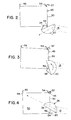
- This discharge member 20 is movable between two positions. In a first position ( Figure 4) the discharge member 20 cooperates with the discharge chute 14 so as to deflect grass clippings and/or residue upwards and backwards into the associated grass bag 50. In a second position ( Figure 2) the discharge member 20 cooperates with the discharge chute 14 in order to deflect grass clippings downward into the lawn for eventual disintegration. The discharge member is biased into the second position.
- the discharge member 20 disclosed is utilized in a rear discharge lawn mower, it is mounted in the back section of the mower frame 10.
- the mounting for the preferred rotating discharge member 20 includes mounting brackets 30 and an air dispersal member 40.
- the mounting brackets 30 are adapted to interconnect the air dispersal member 40 fixedly to the mower frame 10. As the mower is a rear discharge mower, the mounting brackets 30 are fixedly bolted to the aft section of the mower frame 10 so as to extend axially off of such frame.
- the mounting brackets 30 allow for room for the mowing discharge member 20 and the rear discharge chute 14, while at the same time fixedly interconnecting the air dispersal member 40 to the frame 10.
- the air dispersal member 40 serves as an intermediate member between the mower frame 10 and the grass bag 50, serving primarily to cooperate with the latter in grass collection.
- the particular air dispersal 40 member disclosed is a flat sheet of stamped steel 41 which has a clearance opening 42 and a multitude of air openings 43.
- the air dispersal member 40 is mounted off of the back of the mower frame 10 by the mounting brackets 30 with the clearance opening 42 generally in line with the discharge chute 14 of the mower deck 11.
- the discharge member 20 itself is located in the clearance opening 42 pivotally or rotatively mounted to the air dispersal member 40 for movement between the first position - directing the clippings upward and backward and a second position - directing the clippings downward (contrast Figure 4 with Figure 2).
- the discharge member 20 is biased in the second position such that upon removal or non-existence of the grass bag 50, the discharge member 20 is located to direct the grass clippings downward onto the lawn instead of through the clearance opening 42 in the air dispersal member.
- the preferred form of biasing is a spring 28.
- weights or an off center pivot point could be utilized.
- the deflection surface 27 of the discharge member 20 is in contact (or close proximity with) the discharge chute 14 (top of bottom edge respectively). This provides for efficient transfer or directing of the clippings.
- a hanger bar 45 is located across the top of the air dispersal member. This hanger bar 45, together with the alignment hooks 46 thereon, are for mounting of the grass bag 50 onto the air dispersal member 40 (and thus the mower frame 10).
- the grass bag 50 itself has a generally rectangular frame 51 surrounded by a porous material 52 on all but one side. This side is the open front 53.
- a front handle 54, a rear handle 55 and two reinforcing bars 56 complete the assembly.
- two mounting brackets 57 locating extending off of the top front edge of the frame 51 hook over the hanger bar 45 at the alignment hooks 46 so as to selectively interconnect the grass bag 50 to the air dispersal member 40.
- the act of lowering these mounting brackets 57 of the grass bag 50 onto the hanger bar 45 has the effect of causing the bottom front edge 59 of the grass bag to contact the then exposed activation section 24 of the discharge member 20 ( Figure 2). Due to the angular orientation of this activation section 24 in respect to the dispersal member 30 the edge 59 of the grass bag 50 is temporarily affixed in a position to activate the discharge member 20.
- the air openings 43 in the air dispersal member 40 are oversized, each being some 12 mm deep by 100 mm long. This allows for efficient air movement from the grass bag 50 to the surrounding atmosphere irrespective of the condition of the porous material 52 of such grass bag. Further, the cooperation of the discharge member 20 and air dispersal member 40 also provides that there is minimal residual leakage of grass clipping out of these openings 43.
Landscapes
- Life Sciences & Earth Sciences (AREA)
- Environmental Sciences (AREA)
- Harvester Elements (AREA)
Description
- Figure 1
- is a respective view of the back section of a rear discharge riding lawn mower incorporating the present invention;
- Figures 2-4
- are a series of cutaway side views of the rear discharge area of the lawn mower of Figure 1 detailing the conversion of the lawn mower to grass collection mode;
- Figure 5
- is a downward partially separated representational view of the lawn mower of Figure 1.
Claims (5)
- Lawn mower having a discharge chute (14) with an end and a connected grass bag (50), characterized by a discharge member (20), pivoting means to pivotally connect said discharge member (20) to the end of the discharge chute (14) with a first position directing clippings outward and a second position directing clippings downward, biasing means (28) to bias said discharge member (20) in said second position, and alteration means for the connection of the grass bag (50) to change over said discharge member (20) to said first position.
- Lawn mower according to claim 1, characterized by the addition of an air dispersal member (40) and said pivoting means including said air dispersal member (40).
- Lawn mower according to claim 1, characterized by the addition of a spring (28) and said biasing means including said spring.
- Lawn mower according to claim 1, characterized in that the grass bag (50) is mounted to a hanger bar (45) and has an in use position and said alteration means includes the connection of the grass bag (50) the to said hanger bar (45) to the grass bags (50) in use connected position.
- Lawn mower according to claim 1, characterized by an air dispersal member (40), means to fixedly connect said air dispersal member (40) to the frame (10) of the lawn mower adjacent to the discharge chute (14), a discharge member (20), pivoting means to mount said discharge member (20) to said air dispersal member (40) off of the end of the discharge chute (14), said discharge member (20) being movable between a first position directing clippings outward and a second position directing clippings downward, spring means (28) to bias said discharge member (20) in said second position, pivot means to connect the grass bag (50) to said dispersal member (40), the grass bag (50) having a use position in respect to said air dispersal member (40), and alteration means for the connection of the grass bag to said use position to change over said discharge member to said first position.
Applications Claiming Priority (2)
| Application Number | Priority Date | Filing Date | Title |
|---|---|---|---|
| US08/424,209 US5517811A (en) | 1995-04-19 | 1995-04-19 | Pivoting grass chute |
| US424209 | 1995-04-19 |
Publications (2)
| Publication Number | Publication Date |
|---|---|
| EP0738462A1 EP0738462A1 (en) | 1996-10-23 |
| EP0738462B1 true EP0738462B1 (en) | 2001-01-24 |
Family
ID=23681871
Family Applications (1)
| Application Number | Title | Priority Date | Filing Date |
|---|---|---|---|
| EP96104506A Expired - Lifetime EP0738462B1 (en) | 1995-04-19 | 1996-03-21 | Lawn mowers having a pivoting grass chute |
Country Status (4)
| Country | Link |
|---|---|
| US (1) | US5517811A (en) |
| EP (1) | EP0738462B1 (en) |
| CA (1) | CA2153080A1 (en) |
| DE (1) | DE69611629T2 (en) |
Cited By (1)
| Publication number | Priority date | Publication date | Assignee | Title |
|---|---|---|---|---|
| USD685822S1 (en) | 2013-01-04 | 2013-07-09 | Mtd Products Inc | Blower attachment for a walk-behind lawn mower |
Families Citing this family (8)
| Publication number | Priority date | Publication date | Assignee | Title |
|---|---|---|---|---|
| GB9608116D0 (en) * | 1996-04-19 | 1996-06-26 | Mcmurtry Ltd | Mower |
| US6195971B1 (en) | 1997-08-22 | 2001-03-06 | Murray, Inc. | Grass collector arrangement for a rear discharge mower |
| US6105350A (en) * | 1998-08-28 | 2000-08-22 | The Toro Company | Multi-port hopper exhaust apparatus |
| JP2006067915A (en) * | 2004-09-02 | 2006-03-16 | Honda Motor Co Ltd | Lawn mower |
| US20060272309A1 (en) * | 2005-06-03 | 2006-12-07 | Electrolux Professional Outdoor Products, Inc. | Collection system |
| EP2499894B1 (en) * | 2011-03-14 | 2014-07-02 | Robert Bosch GmbH | Lawnmowers |
| IT201800007555A1 (en) * | 2018-07-27 | 2020-01-27 | Stiga Spa In Breve Anche St Spa | Bag for lawn mowers with grass conveyor |
| US11716932B2 (en) * | 2020-02-19 | 2023-08-08 | Excel Industries, Inc. | Side-discharge to bagging conversion assembly for mower |
Family Cites Families (5)
| Publication number | Priority date | Publication date | Assignee | Title |
|---|---|---|---|---|
| GB942056A (en) * | 1959-07-06 | 1963-11-20 | Charles Herbert Christiansen | Improvements in or relating to forage harvesting units |
| US3757503A (en) * | 1971-05-10 | 1973-09-11 | T Soldavini | Lawnmower and grass collector |
| FR2247152A1 (en) * | 1973-10-16 | 1975-05-09 | Bernard Moteurs | Rotary lawn mower with removable grass box - cover for the box pivots down to enclose blades when box is removed |
| US3928956A (en) * | 1974-11-29 | 1975-12-30 | Perfection Mfg Co | Rear mounted grass catcher |
| US4203276A (en) * | 1978-08-07 | 1980-05-20 | Mtd Products Inc. | Lawn mower and grass catcher |
-
1995
- 1995-04-19 US US08/424,209 patent/US5517811A/en not_active Expired - Fee Related
- 1995-06-30 CA CA002153080A patent/CA2153080A1/en not_active Abandoned
-
1996
- 1996-03-21 EP EP96104506A patent/EP0738462B1/en not_active Expired - Lifetime
- 1996-03-21 DE DE69611629T patent/DE69611629T2/en not_active Expired - Fee Related
Cited By (1)
| Publication number | Priority date | Publication date | Assignee | Title |
|---|---|---|---|---|
| USD685822S1 (en) | 2013-01-04 | 2013-07-09 | Mtd Products Inc | Blower attachment for a walk-behind lawn mower |
Also Published As
| Publication number | Publication date |
|---|---|
| US5517811A (en) | 1996-05-21 |
| DE69611629T2 (en) | 2002-09-12 |
| CA2153080A1 (en) | 1996-10-20 |
| DE69611629D1 (en) | 2001-03-01 |
| EP0738462A1 (en) | 1996-10-23 |
Similar Documents
| Publication | Publication Date | Title |
|---|---|---|
| US5224326A (en) | Lawn mowers | |
| EP1138187B1 (en) | Mower with a grass catcher | |
| US5816035A (en) | Mower deck mounting system | |
| US3855763A (en) | Self-propelled rotary lawn mower | |
| US5943848A (en) | Mower conditioner swathboard support with down stop | |
| CA2044889C (en) | Mower deck height adjustment mechanism | |
| US6050072A (en) | Riding lawnmower comprising particularly a collector for cut grass | |
| EP0745316B1 (en) | Lawn mower | |
| US5517811A (en) | Pivoting grass chute | |
| CA1266183A (en) | Ride-on rotary lawnmower | |
| US6996963B2 (en) | Utility cart for use on a lawnmower | |
| US3874151A (en) | Self-propelled lawn mower | |
| US6966169B2 (en) | Mowing machine chute cleaner apparatuses and methods | |
| EP0941647B1 (en) | Four bar linkage mounting for mowers | |
| EP1312250A1 (en) | Lawn-mower with tipping device for the bin | |
| JP2556614B2 (en) | Edge lawn mower | |
| JP3527191B2 (en) | Riding mower | |
| US3874149A (en) | Self-propelled lawn mower | |
| JPH0214346Y2 (en) | ||
| EP1312249B1 (en) | Cutting blade for lawn-mower machine | |
| DK1656825T3 (en) | Lawnmower | |
| JP7785337B2 (en) | Grass cutting and collection device | |
| CA2513894A1 (en) | Machine for removing vegetation | |
| JP2003210018A (en) | Moving agricultural machine | |
| JPH04647Y2 (en) |
Legal Events
| Date | Code | Title | Description |
|---|---|---|---|
| PUAI | Public reference made under article 153(3) epc to a published international application that has entered the european phase |
Free format text: ORIGINAL CODE: 0009012 |
|
| AK | Designated contracting states |
Kind code of ref document: A1 Designated state(s): DE FR GB IT SE |
|
| 17P | Request for examination filed |
Effective date: 19970219 |
|
| GRAG | Despatch of communication of intention to grant |
Free format text: ORIGINAL CODE: EPIDOS AGRA |
|
| 17Q | First examination report despatched |
Effective date: 20000511 |
|
| GRAG | Despatch of communication of intention to grant |
Free format text: ORIGINAL CODE: EPIDOS AGRA |
|
| GRAH | Despatch of communication of intention to grant a patent |
Free format text: ORIGINAL CODE: EPIDOS IGRA |
|
| GRAH | Despatch of communication of intention to grant a patent |
Free format text: ORIGINAL CODE: EPIDOS IGRA |
|
| GRAH | Despatch of communication of intention to grant a patent |
Free format text: ORIGINAL CODE: EPIDOS IGRA |
|
| RIC1 | Information provided on ipc code assigned before grant |
Free format text: 7A 01D 34/71 A, 7A 01D 34/49 B |
|
| GRAA | (expected) grant |
Free format text: ORIGINAL CODE: 0009210 |
|
| AK | Designated contracting states |
Kind code of ref document: B1 Designated state(s): DE FR GB IT SE |
|
| REF | Corresponds to: |
Ref document number: 69611629 Country of ref document: DE Date of ref document: 20010301 |
|
| ITF | It: translation for a ep patent filed | ||
| ET | Fr: translation filed | ||
| PLBE | No opposition filed within time limit |
Free format text: ORIGINAL CODE: 0009261 |
|
| STAA | Information on the status of an ep patent application or granted ep patent |
Free format text: STATUS: NO OPPOSITION FILED WITHIN TIME LIMIT |
|
| REG | Reference to a national code |
Ref country code: GB Ref legal event code: IF02 |
|
| 26N | No opposition filed | ||
| PGFP | Annual fee paid to national office [announced via postgrant information from national office to epo] |
Ref country code: SE Payment date: 20020325 Year of fee payment: 7 |
|
| PG25 | Lapsed in a contracting state [announced via postgrant information from national office to epo] |
Ref country code: SE Free format text: LAPSE BECAUSE OF NON-PAYMENT OF DUE FEES Effective date: 20030322 |
|
| EUG | Se: european patent has lapsed | ||
| PG25 | Lapsed in a contracting state [announced via postgrant information from national office to epo] |
Ref country code: IT Free format text: LAPSE BECAUSE OF NON-PAYMENT OF DUE FEES;WARNING: LAPSES OF ITALIAN PATENTS WITH EFFECTIVE DATE BEFORE 2007 MAY HAVE OCCURRED AT ANY TIME BEFORE 2007. THE CORRECT EFFECTIVE DATE MAY BE DIFFERENT FROM THE ONE RECORDED. Effective date: 20050321 |
|
| PGFP | Annual fee paid to national office [announced via postgrant information from national office to epo] |
Ref country code: GB Payment date: 20080318 Year of fee payment: 13 |
|
| PGFP | Annual fee paid to national office [announced via postgrant information from national office to epo] |
Ref country code: FR Payment date: 20080314 Year of fee payment: 13 Ref country code: DE Payment date: 20080430 Year of fee payment: 13 |
|
| GBPC | Gb: european patent ceased through non-payment of renewal fee |
Effective date: 20090321 |
|
| REG | Reference to a national code |
Ref country code: FR Ref legal event code: ST Effective date: 20091130 |
|
| PG25 | Lapsed in a contracting state [announced via postgrant information from national office to epo] |
Ref country code: DE Free format text: LAPSE BECAUSE OF NON-PAYMENT OF DUE FEES Effective date: 20091001 |
|
| PG25 | Lapsed in a contracting state [announced via postgrant information from national office to epo] |
Ref country code: GB Free format text: LAPSE BECAUSE OF NON-PAYMENT OF DUE FEES Effective date: 20090321 Ref country code: FR Free format text: LAPSE BECAUSE OF NON-PAYMENT OF DUE FEES Effective date: 20091123 |