EP0737412B1 - Defective earth testing for an electric fence energizer - Google Patents
Defective earth testing for an electric fence energizer Download PDFInfo
- Publication number
- EP0737412B1 EP0737412B1 EP95905287A EP95905287A EP0737412B1 EP 0737412 B1 EP0737412 B1 EP 0737412B1 EP 95905287 A EP95905287 A EP 95905287A EP 95905287 A EP95905287 A EP 95905287A EP 0737412 B1 EP0737412 B1 EP 0737412B1
- Authority
- EP
- European Patent Office
- Prior art keywords
- voltage
- value
- capacitor
- secondary winding
- winding
- Prior art date
- Legal status (The legal status is an assumption and is not a legal conclusion. Google has not performed a legal analysis and makes no representation as to the accuracy of the status listed.)
- Expired - Lifetime
Links
Images


Classifications
-
- G—PHYSICS
- G01—MEASURING; TESTING
- G01R—MEASURING ELECTRIC VARIABLES; MEASURING MAGNETIC VARIABLES
- G01R27/00—Arrangements for measuring resistance, reactance, impedance, or electric characteristics derived therefrom
- G01R27/02—Measuring real or complex resistance, reactance, impedance, or other two-pole characteristics derived therefrom, e.g. time constant
- G01R27/20—Measuring earth resistance; Measuring contact resistance, e.g. of earth connections, e.g. plates
- G01R27/205—Measuring contact resistance of connections, e.g. of earth connections
-
- H—ELECTRICITY
- H05—ELECTRIC TECHNIQUES NOT OTHERWISE PROVIDED FOR
- H05C—ELECTRIC CIRCUITS OR APPARATUS SPECIALLY DESIGNED FOR USE IN EQUIPMENT FOR KILLING, STUNNING, OR GUIDING LIVING BEINGS
- H05C1/00—Circuits or apparatus for generating electric shock effects
- H05C1/04—Circuits or apparatus for generating electric shock effects providing pulse voltages
-
- H—ELECTRICITY
- H05—ELECTRIC TECHNIQUES NOT OTHERWISE PROVIDED FOR
- H05C—ELECTRIC CIRCUITS OR APPARATUS SPECIALLY DESIGNED FOR USE IN EQUIPMENT FOR KILLING, STUNNING, OR GUIDING LIVING BEINGS
- H05C3/00—Other circuits or apparatus
Definitions
- the present invention relates to a method and device for coupling to a control circuit a voltage representative of the voltage over a secondary winding of a transformer used in an electric fence energizer and in particular to a method and device for testing the earth connection and measurement of the quality thereof for an electric fence energizer, the energizer being the capacitor discharge type, in particular for determining whether the earth connection of the fence is defective.
- the energizer is principally a high voltage pulse generator and comprises in the conventional way a capacitor which is charged to a high voltage and is discharged to the primary winding of a transformer, the secondary winding of the transformer providing a very high voltage to an electric fence circuit.
- Electric fences conventionally comprise a bare electric conductor, one end of which, the proximate end, is connected to one output terminal of the electric fence energizer which provides, on its output terminals, high voltage pulses to the current conducting portion of the electric fence.
- the other output terminal of the energizer is connected to earth or grounded.
- the earth connection is conventionally made by the method that a pointed electrically conductive part, such as a metal part, an earth connection post, is inserted in the ground or soil close to the electric fence energizer as deeply as possible, preferably so deeply that a contact is obtained with humid layers in the ground.
- a pointed electrically conductive part such as a metal part, an earth connection post
- a method for measuring the quality of the connection to earth includes inserting a second earth connection post into the ground or soil at a place so far away from the first normal earth connection post that they do not influence each other. No significant current will then flow in the second earth connection post, and thus it is sufficient to use a second earth connection post having a simpler construction.
- the voltage is measured from the normal earth connection of the electric fence device to this second earth connection post and if the voltage is too high, the earth connection is considered to be bad.
- This measurement is normally made by connecting a glow-discharge tube, which is arranged to be illuminated at the desired voltage difference between the earth connection posts.
- the disadvantages of this method are several: An extra earth connection post is required, this extra earth connection post must be connected correctly to earth and the signal does not consider the load from the fence, to which the energizer is subjected.
- the quality of the fence isolation is determined by operating a switch T1, which closes an electric path from an output terminal of a secondary winding in a step-up transformer L2 to ground through a resistor R10 and a glow-charge tube I2.
- the switch When the switch is closed, the glow-charge tube should be illuminated for a good fence isolation and thus a good connection to earth.
- An electric fence energizer is disclosed in US Patent No. 3,378,694 for T.F. Griffith and comprises an energy storage capacitor 72 connected to a primary winding 30, 32 in a transformer 26, which has a secondary winding 28 connected to the electric conductor 16 in an electric fence and to an earth connection device 34 deeply inserted into the ground.
- a sensing device 70, 74 the varying humidity of the earth can be sensed and the resistance of the resistor 68 be adjusted for compensation thereof.
- Earth testing means for an electric fence is disclosed in the published European patent application No. 0 248 133.
- the output terminal of the energizer which is to connected to earth is, through isolation capacitors C 1 and C 2 and a calibration resistor R 1 , also connected to one input of a differential voltage indicator DIVI, the other input thereof being connectable, through manual operation of a switch S1, to a secure mains earth, such as the earth or neutral line of the mains supply.
- the voltage indicator displays the potential difference between the fence earth and the secure mains earth.
- the input of the voltage indicator may be preceded by a peak voltage monitoring means holding the worst case test voltage to be displayed by the voltage indicator.
- a simple manual method of testing a fence earth connection is described, see col. 2, lines 16 - 34.
- the circuits for determining the quality of the earth connection are only connected to the primary side of the transformer and thus always sensing voltages or other characteristics on the primary side. No galvanic connections need to be made to the fence circuit on the secondary side.
- an exterior earth connection such as an earth connection post inserted into the ground.
- the exterior earth connection is coupled to an output terminal of the energizer.
- the electric fence energizer comprises in the conventional way a step-up transformer having a primary winding and a secondary winding, the terminals of the secondary winding also being the output terminals of the energizer.
- One exterior terminal of the secondary winding is connected to the conductor in the electric fence and the second exterior terminal thereof is thus connected to the exterior earth connection.
- High voltage pulses are induced over the secondary winding of the transformer when voltage pulses are applied over the primary winding.
- a voltage is obtained which represents, and for instance can be essentially proportional to, the voltage between the second terminal of the secondary winding, which is connected to the exterior earth connection, and an artificial earth or ground potential.
- This artificial earth potential is an electronics or signal ground potential which is used as a ground or earth connection by electronic control devices in the electric fence energizer and for an electric fence energizer, supplied with alternating current from for instance the public electric energy distribution network, is the potential on one of the mains supply conductors terminals such as the potential on the neutral line or a phase line thereof.
- the voltage over a small portion of the secondary winding is obtained or recovered capacitively, i.e. by a capacitive coupling to this small winding portion, preferably by means of an extra winding in the transformer, this winding forming one plate in a capacitor and the other plate being formed by the small portion of the secondary winding.
- the obtained voltage can be evaluated for a determination of the quality of the earth connection by a determination of various characteristic quantities, such as that its maximum swing or maximum deviation from a stationary value with a definite polarity is determined, that the time difference is determined, before the obtained voltage starts to deviate from its stationary value when a high voltage pulse is induced, and/or returns to its stationary value after induction of a high voltage pulse, etc.
- the absolute voltage difference can thus be determined between a voltage value which exists quite or immediately before or a very small time before the time when a voltage pulse is applied to the primary winding for the induction of a high voltage pulse over the secondary winding, and a voltage peak value which has the largest absolute magnitude and which occurs after the voltage pulse has been applied over the primary winding.
- the value of the determined absolute difference may then be compared to a predetermined threshold value for deciding that an unsatisfactory connection to earth exists, in the case where the determined absolute difference exceeds the predetermined value.
- the obtained voltage can be coupled, substantially only for a predetermined polarity, to a charging circuit for a capacitor which is discharged over a known resistor.
- the voltage over this capacitor is evaluated for determination of the quality of the earth connection.
- the time difference can be determined between the time when the induction of a high voltage pulse over the secondary winding starts, and the time when a voltage change of the signal which is obtained capacitively starts thereafter.
- the maximum discharge voltage can also be determined.
- the time difference can also be determined between the time when the induction of a high voltage pulse over the secondary winding starts, and the time when the signal capacitively obtained after that returns to a stationary value which it had before the high voltage pulse, during the intermediate times between the high voltage pulses, when stationary electric conditions in the electric circuits at least partially exist.
- This measured time difference represents a measure of or provides indirectly the maximum charge voltage of the capacitor.
- the time difference is determined between the time, when the induction of a high voltage pulse starts over the secondary winding, and the time, when the value of the capacitively obtained voltage after that again obtains essentially its value before the start of induction of the high voltage pulse after having deviated, during the induction of the high voltage pulse, from this previous value.
- the second time may be taken as the time when the obtained voltage again deviates from its previous value, which existed at the start of the voltage pulse, by a value, the absolute magnitude of which is lower than a predetermined, in particular small, voltage value.
- a small voltage is here meant a voltage being a small fraction of the total amplitude of the voltage signal.
- the determined time difference can be compared to a predetermined threshold value, a time threshold, and it can be decided that a good connection to earth exists, if the measured or determined time difference exceeds this predetermined threshold value.
- the time difference can also be determined between the time when a voltage pulse starts to be applied to the primary winding for induction of a high voltage pulse and the time, when after that the obtained voltage starts to change or vary, in particulate deviates from its previous value at the start of the voltage pulse by a value, the absolute magnitude of which exceeds a predetermined, in particular small, voltage value.
- a small voltage is as above meant a voltage being a small fraction of the total amplitude of the obtained voltage.
- the determined time difference can also as above be compared to a predetermined threshold time value for deciding that a satisfactory connection to earth exists, in the case where the determined or measured time difference exceeds this predetermined threshold value.
- the voltage pulses are assumed to be applied to the primary winding, so that sufficient time periods exist between those time periods, during which these pulses are applied to the primary winding and during which high voltage pulses are induced over the secondary winding, in order that, during these sufficiently long, intermediate time periods, the electric condition in the electric fence energizer and particularly in its control circuits and the transformer will take an essentially stationary state.
- the capacitively obtained voltage can be coupled to a charging circuit for a capacitor.
- This coupling is made or is effective only for such a voltage over the secondary winding which has an essentially predetermined polarity, in particular in relation to the voltage which is stationarily applied over the capacitor.
- the capacitor is then discharged over a resistor, and the voltage at a charging of and/or a discharging of this capacitor through the resistor is evaluated for a determination of the quality of the connection to earth.
- this coupling can then be made in such a way that the voltage controls the charging of the capacitor, so that the capacitor is charged to essentially an extreme value or a peak value of the voltage.
- the charge and/or discharge voltage is in this case preferably sensed in the respective cases by a transistor amplifier.
- the time can also be determined, when the voltage starts to change from a previous stationary value, in particular the time, when the voltage deviates from a previous stationary value by a value, the absolute magnitude of which exceeds a predetermined, particular small, value, the word small here and below being used as defined above.
- the time is determined, when the voltage returns to a previous stationary value, in particular the time, when the voltage again deviates from a previous stationary value by a value, the absolute magnitude of which is smaller than a predetermined, in particular small, value.
- the device for determining the quality of a connection to earth thus comprises a generator for generation of voltage pulses over the primary winding of the transformer, whereby high voltage pulses are induced over the secondary winding.
- a generator for generation of voltage pulses over the primary winding of the transformer whereby high voltage pulses are induced over the secondary winding.
- means for obtaining a voltage representing the voltage between the second exterior terminal of the secondary winding which is connected to the exterior earth connection, and a ground potential.
- an evaluation circuit arranged for evaluation of the obtained voltage.
- the means for obtaining the voltage comprises a first capacitor plate in a first capacitor, the second plate of which is formed by a small portion of the secondary winding.
- the first capacitor plate in the first capacitor then advantageously comprises an extra winding in the transformer, this extra winding being located at or adjacent the secondary winding.
- the extra winding in the transformer can then comprise a layer of winding wire arranged at or close to one or several layers, for instance between two successive layers, of winding wire which are comprised in
- the evaluation circuit may be connected to the first capacitor plate for evaluation of the voltage over the first capacitor.
- the evaluation circuit comprises advantageously means for determining in the obtained voltage the absolute difference between the voltage value which exists quite before or a very small time before the time when a voltage pulse is applied over the primary winding for induction of a high voltage pulse, and the voltage value which has the largest absolute magnitude and is achieved after the voltage pulse has been applied over the primary winding.
- the evaluation circuit can then comprise comparator means for comparing the determined absolute difference to a predetermined threshold value and means for deciding that an unsatisfactory connection to earth exists, in the case where the determined absolute difference exceeds the predetermined value.
- the evaluation circuit can in another aspect comprise means for determining the time difference between the time, when the induction of a high voltage pulse starts over the secondary winding, and the time when the value of the capacitively obtained voltage after that returns essentially to the value which it had before the start of induction of the high voltage after having deviated, during the induction process, from this previous value.
- the evaluation circuit can then as above comprise comparator means for comparing the determined time difference to a predetermined time threshold value and means for deciding that a good connection to earth exists if the determined time difference exceeds this predetermined value.
- the evaluation circuit can comprise means for determining, in the obtained voltage, the time difference between the time, when a voltage pulse starts to be applied over the primary winding for induction of a high voltage pulse, and the time, when after that the obtained voltage starts to change or vary, in particular deviates from its previous value at the start of the voltage pulse by a value, which exceeds a predetermined, in particular small, voltage value.
- the evaluation circuit may as above comprises comparator means for comparing the determined time difference to a predetermined threshold value and means for deciding that a satisfactory connection to earth exists, in the case where the determined time difference exceeds this predetermined threshold value.
- the evaluation circuit may comprise a second capacitor and a charging circuit for charging it.
- a rectifier such as suitable semiconductor diode is arranged for coupling the voltage on the first capacitor plate in the first capacitor to the charging circuit for the second capacitor.
- a resistor is connected to the second capacitor, through which it can be discharged and there is an evaluation device for determining the charge voltage and/or discharge voltage of the second capacitor.
- the second capacitor may have its first terminal or plate connected to the ground potential and its second terminal or plate connected to the rectifier.
- the evaluation device comprises advantageously a connection line for applying the voltage over the second capacitor to one terminal of a resistor, the other terminal of which is connected to a direct voltage. This direct voltage is a supply voltage and has a constant value as related to the signal or artificial ground.
- the voltage over the second capacitor can be discharged through the resistor.
- the resistor comprises preferably a voltage divider circuit, the central connection of which is connected to the base of a transistor.
- the method of obtaining the voltage over a small part of the secondary winding capacitively and supply it to the control circuit can generally be used in an electric fence energizer to couple a portion of the voltage over the secondary winding to some control circuit in the electric fence energizer. Then, as above, the voltage can be obtained at an end or a terminal of an extra winding in the transformer arranged at or close to the secondary winding.
- a first capacitor plate in a capacitor is used, the second plate of which is formed by a small portion of the secondary winding, and this first capacitor plate advantageously comprises an extra winding in the transformer and this winding is then arranged close to or at the secondary winding.
- the extra winding in the transformer comprises in a preferred embodiment one layer of winding wire arranged close to, for instance directly on top of or inside, a layer of winding wire which is a part of the secondary winding.
- an electric fence energizer which comprises a transformer having a primary winding and a secondary winding, where one exterior terminal of the secondary winding is connected to the conductor in the electric fence and the other exterior connection thereof is connected to an exterior earth connection device, and which further comprises a generator for generating voltage pulses over the primary winding, whereby high voltage pulses are induced over the secondary winding
- a device may thus generally be arranged for coupling a voltage representative of the voltage over the secondary winding to a control circuit in the electric fence energizer.
- This device then comprises a first capacitor plate in a capacitor, the other plate of which is formed by a small part of the secondary winding.
- the first capacitor plate in the capacitor is preferably an extra winding in the transformer arranged at or adjacent the secondary winding.
- the extra winding in the transformer can then comprise one layer of winding wire arranged at or adjacent to one or preferably several layers of winding wire, for instance between two successive layers, which are included in the secondary winding.
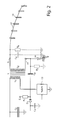
- An electric circuit for an electric fence energizer is illustrated, in its principal parts, by the circuit diagram of Fig. 1.
- the alternating voltage from an electric energy distribution network is supplied between mains terminals 1 and 3 to a charging circuit 5.
- a microprocessor 7 controls the charging circuit 5 for charging an energy storage capacitor C 1 which has a large capacitance and which is charged by the charging circuit 5 to a high voltage.
- the storage capacitor C 1 has its one terminal connected to signal ground and the other terminal is connected to a primary winding L 1 of a transformer T which is provided with a secondary winding L 2 .
- the secondary winding L 2 feeds the fence circuit or fence conductor which is connected between the terminals 9 and 11 of the secondary winding, these terminals forming the output terminals of the energizer.
- the other end of the primary winding L 1 is through a control switch 13 connected to signal ground, this switch being controlled by a signal TY from the microprocessor 7.
- the switch 13 can in the conventional way be constructed as a thyristor circuit, not shown, containing a thyristor, the positive terminal of which is connected to the primary winding L 1 and the negative terminal of which is connected to signal ground and the gate electrode of which, possibly through some amplifying circuit, is controlled by the signal TY.
- the transformer T has, in addition, an extra short winding L 3 , one end of which is free and the other end of which, through a resistor R 1 , is connected to a first positive supply DC voltage E 1 of for instance 12 V, as seen in relation to the signal ground.
- This other end is further, through a diode D 1 , connected to a first terminal of a capacitor C 2 , the other terminal of which is connected to signal or electronics ground.
- the charge voltage of the capacitor C 2 is sensed by means of a transistor amplifier stage, by the method that its first plate or terminal is connected, through two resistors R 2 , R 3 which are connected to each other in series, to a second positive supply voltage E 2 of for instance 5 V, as taken in relation to electronics ground.
- the middle point between the resistors R 2 and R 3 is connected to the base of a transistor T 1 .
- the transistor T 1 has its collector connected to the second positive supply voltage E 2 through a resistor R 4 and a signal is obtained on the collector and is provided to an input terminal PGND of the microprocessor 7.
- the emitter of the transistor T 1 is connected to signal ground.
- the microprocessor 7 evaluates the voltage signal on the input terminal PGND and shows an observed faulty earth connection by means of an indicator or display device 15, for instance in the shape of or comprising a light emitting diode, to which, for a defective earth connection, a voltage is applied and which is then illuminated.
- the high voltage winding L 2 comprises eight layers of thin copper wire 17 wound on a core 19 and isolated by plastic sheets 21 between the layers.
- the isolating plastic sheet 23 inside the extra winding 25 should be sufficiently thick in order to prevent flash-over or electrical break-through between this winding and the outermost layer in the high voltage winding L 2 .
- the extra winding L 3 can be constructed in the shape of an electrically conductive sheet or metal plate instead of being wound by copper wire in the layer 25, as is illustrated in Fig. 3.
- FIG. 2 An equivalent circuit diagram of the right portion of the circuit diagram of Fig. 1, together with a schematically indicated fence circuit, is shown in Fig. 2.
- the extra winding L 3 is here shown in the shape of a capacitor C 3 , which is connected to one pole or terminal of the secondary winding L 2 , the output terminal 11, which is also to be connected to earth.
- the earth connection of the fence circuit is in the conventional way made by means of an earth connection post 16 which is well inserted into the ground and is electrically represented by a resistor R 5 , which is illustrated in dotted lines and then also is connected to the same output terminal 11 of the secondary winding L 2 .
- the electric fence is shown as a conductor 17 located on posts or standards 19. An equivalent circuit for this portion is the resistor R 6 , which is connected to the second output terminal of the secondary winding, the terminal 9, and to ground, and a capacitor C 4 connected in parallel to this resistor R 6 .
- the capacitor C 4 represents the capacitance of the conductor 17 to ground which to a small extent influences the defective earth connection measurement described hereinafter.
- the ground connection which is used by the circuits on the primary side of the transformer, i.e. the ground connection for the storage capacitor C 1 , the capacitor C 2 , the transistor T 1 and the switch 13, also called signal or electronics ground, is, as been already mentioned, in a practical embodiment of the electric fence energizer a connection to one of the poles of the mains voltage (terminals 1 or 3), either a phase or the neutral or ground conductor.
- the voltage of the neutral conductor but also that of the phase voltage, for instance 230 Volts, 50 Hz can be considered as ground potential.
- the capacitor C 2 can only be charged for pulses having a negative polarity compared to the stationary voltage V 21,stat on the first terminal of the capacitor C 2 (the point 21) or roughly electronics ground from the capacitance C 3 or the extra winding L 3 , so that in this case the charging of the capacitor C 3 is negligible.
- the voltage V 21 at the first terminal or plate of the capacitor C 2 in the point 21 is lower than the small positive voltage V 21,stat , also a voltage is induced having a high absolute value over the capacitance C 3 and then the charging of the capacitor C 2 starts by the fact that current flows therefrom to the equivalent capacitance C 3 .
- the charging circuit of the capacitor C 2 is dimensioned to very rapidly achieve the charging.
- the discharge circuit of the same capacitor C 2 consisting of principally the resistors R 2 and R 3 is dimensioned to give a discharge time, which is significantly longer than the charging time and longer than the duration of the induced high voltage pulse in order to facilitate the measurement by means of the transistor circuit and the microprocessor 7.
- the voltage V 21 in the point 21, at charging the capacitor C 2 will all the time correspond the voltage which is applied through the diode D 1 from the extra winding L 3 , as long as this voltage, at the start of the charging, is lower than the mentioned small positive voltage V 21,stat and at a continued charging is lower than the earlier voltage over the capacitor C 2 . It can also be described by the wording that the voltage over the capacitor C 2 locks to the most negative voltage obtained from the extra winding L 3 .
- These times t 1 , t 2 for passing the voltage level V 21,stat - V 21,oms1 are detected by the microprocessor 7, which for each discharge cycle of the storage capacitor C 1 uses the times t 1 , t 2 together with the time t 0 , when the discharge of the storage capacitor C 1 is started, to evaluate if a satisfactory earth connection of the fence circuit exists.
- the microprocessor 7 calculates the time differences between these times t 0 , t 1 and t 2 , for instance the differences t 1 - t 0 and t 2 - t 0 , and compares the calculated time differences to various suitable predetermined threshold values.
- the time 0 in the diagram is the time to, when the switch 13 as commanded by the microprocessor 7 is switched to a conductive state for the start of the discharge of the storage capacitor C 1 through the primary winding L 1 .
- a correct earth connection essentially only a large positive high voltage pulse is obtained on the secondary side.
- the earth connection of the terminal 11 is not quite good, i.e. if the resistance R 5 has a significant magnitude compared to the effective resistance R 6 of the electric fence itself to earth, for instance is at least 10 % thereof, the potential level of the voltage pulse over the secondary winding L 2 is displaced. If the voltage over the secondary winding thus for a good connection to earth gave a large positive voltage or voltage pulse to the fence 17 (a high potential at the terminal 9) and a very small negative voltage over the earth connection post (a small negative voltage over the resistor R 5 , i.e.
- This time difference t 2 - t 0 is then also a measure of the magnitude of the negative pulse or the peak value (the smallest value for the polarities used in the figures).
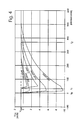
- Typical processes of this kind are illustrated in Fig. 4 by the curves of the voltage over the capacitor C 2 for a resistance R 5 of the earth connection equal to 150 and 200 ohms.
- the equivalent capacitance C 3 is here connected at a position on the winding L 2 , so that a first larger partial winding L 2 ' of the secondary winding L 2 is arranged between the connection position for the capacitor C 3 and the terminal 9, where the conductor 17 of the electric fence circuit is connected, and a second, smaller partial winding L 2 " is arranged between the connection point and the terminal 11, to which the earth connection post 16 is connected.
- the magnitude of the defective earth connection signal which is the negative "after swing” after the proper positive voltage pulse, also depends on the load which the fence is to the electric fence energizer and more particularly to the transformer T. It can mean that limit values for deciding that the earth connection is defective, which values function satisfactorily for normal loads, can appear to be too insensitive, when the electric fence is a light load, what can occur at dry weather.
- the electric fence energizer should be provided with some circuit for sensing the load of the electric fence, compare for instance our patent application filed simultaneously herewith and having the title "A mains operated electric fence energizer", this application being incorporated by reference herein.
- the time limit for defective earth connections can be changed and in particular increased compared to the time limit or threshold value which is valid for a perfect earth connection.
- the limit value for deciding that the earth connection is bad or faulty can be changed from t 2 - t 0 ⁇ 1.5 ms to t 2 - t 0 ⁇ 2.5 ms.
- the arrangement of the extra winding L 3 in the transformer T which is used for coupling a portion of the high voltage of the secondary circuit for an evaluation of that high voltage, can also be used for other purposes in an electric fence energizer.
- a voltage can be obtained, which is representative of the first large high voltage or main pulse, that is positive in the example above, on the secondary side, instead of the following, negative pulse which is used in the embodiment above.
- a voltage representative of the main pulse can be evaluated in a similar way with a measuring capacitor of type C 2 but having a diode of type D 1 connected with an opposite polarity and can for instance provide information of the fact whether this secondary pulse has the magnitude which has been determined by the microprocessor 7 in its control of the charging circuit 5 for the storage capacitor C 1 .
Landscapes
- Life Sciences & Earth Sciences (AREA)
- Insects & Arthropods (AREA)
- Physics & Mathematics (AREA)
- General Physics & Mathematics (AREA)
- Testing Of Short-Circuits, Discontinuities, Leakage, Or Incorrect Line Connections (AREA)
- Testing Relating To Insulation (AREA)
- Measurement Of Resistance Or Impedance (AREA)
- Catching Or Destruction (AREA)
Description
Claims (36)
- A method of determining the quality of the connection to earth obtained by means of an exterior connection inserted into the ground, in particular an earth connection post (16), of an electric fence energizer delivering high voltage pulses to an electric fence (17, 19), the energizer comprising a transformer (T) having a primary winding (L1) and a secondary winding (L2), a first exterior terminal (9) of the secondary winding being connected to a conductor (17) of the electric fence and a second exterior terminal (11) thereof being connected to the earth connection, high voltage pulses being induced over the secondary winding (L2) when voltage pulses are applied to the primary winding (L1), comprising the steps ofcharacterized by coupling, in order to produce the evaluation voltage, capacitively the voltage over a small portion of the secondary winding (L2) to a plate (L3) of a capacitor.producing an evaluation voltage, which represents the voltage between the second exterior terminal (11) of the secondary winding (L2), which is connected to the earth connection, and a ground potential, andevaluating the evaluation voltage,
- A method according to claim 1, characterized in that as the ground potential a potential is used which is utilized as a ground potential by electronic control circuits in the electric fence energizer.
- A method according to any of claims 1 - 2, characterized in that as the ground potential that potential is used, which is obtained on either one of two conductor wires (1, 3), on which the electric fence energizer is supplied with alternating current for the operation thereof.
- A method according to any of claims 1 - 3, characterized in that in the evaluation voltage the absolute difference is determined between a voltage value which exists quite before or a very small time before the time when a voltage pulse is applied to the primary winding (L1) for inducing a high voltage pulse over the secondary winding (L2), and a voltage value which has the largest absolute magnitude and is achieved after the voltage pulse has been applied over the primary winding (L1).
- A method according to claim 4, characterized in that the value of the determined absolute difference is compared to a predetermined value for deciding that an unsatisfactory connection to earth exists in the case where the determined absolute difference exceeds the predetermined value.
- A method according to any of claims 1 - 5, characterized in that the time difference is determined between the time, when the induction of a high voltage pulse starts over the secondary winding (L2), and the time, when the value of the evaluation voltage after that again obtains essentially its value before the start of induction of the high voltage pulse after having deviated, during the induction of the high voltage pulse, from this previous value, in particular again deviates from its previous value at the start of the voltage pulse by a value, the absolute magnitude of which is lower than a predetermined, in particular small, voltage value.
- A method according to claim 6, characterized in that the determined time difference is compared to a predetermined time value and that it is decided that a good connection to earth exists in the case where the determined time difference exceeds this predetermined value.
- A method according to any of claims 1 - 7, characterized in that in the evaluation voltage the time difference is determined between the time when a voltage pulse starts to be applied to the primary winding (L1) for inducing a high voltage pulse and the time, when after that the obtained voltage starts to change or vary, in particular deviates from its previous value at the start of the voltage pulse by a value, the absolute magnitude of which exceeds a predetermined, in particular small, voltage value.
- A method according to claim 8, characterized in that the determined time difference is compared to a predetermined value for deciding that a satisfactory connection to earth exists in the case where the determined time difference exceeds this predetermined value.
- A method according to any of claims 1 - 9, characterized in that the voltage pulses are applied to the primary winding (L1), so that sufficient time periods exist between the time periods, during which these pulses are applied to the primary winding (L1) and during which high voltage pulses are induced over the secondary winding (L2), in order that, during these intermediate periods, the electric condition in the electric fence energizer will take an essentially stationary state.
- A method according to any of claims 1 - 10, characterized inthat in evaluating the evaluation voltage the evaluation voltage is coupled to a charging circuit (E1, R1, D1) for a capacitor (C2),that this coupling is connected only for a voltage over the secondary winding (L2) having an essentially predetermined polarity, in particular in relation to the voltage which is stationarily applied over the capacitor (C2),that the capacitor (C2) is discharged over a resistor (R2, R3), andthat the voltage (V21) for charging and/or discharging this capacitor (C2) through the resistor (R2, R3) is evaluated in order to determine the quality of the connection to earth.
- A method according to claim 11, characterized in that in coupling the evaluation voltage to the charging circuit (E1, R1, D1) for the capacitor (C2) this coupling is made in such a way that the evaluation voltage controls the charging, so that the capacitor (C2) is charged to essentially an extreme value or a peak value of the evaluation voltage.
- A method according to any of claims 11 - 12, characterized in that in evaluating the voltage, when charging or discharging the capacitor (C2), the charge and/or discharge voltage (V21) is sensed in the respective cases by a transistor amplifier.
- A method according to any of claims 11 - 13, characterized in that in evaluating the charge voltage (V21), when charging the capacitor (C2), the time is determined, when the voltage starts to change from a previous stationary value, in particular the time, when the voltage deviates from a previous stationary value by a value, the absolute magnitude of which exceeds a predetermined, in particular small, value.
- A method according to any of claims 11 - 14, characterized in that in evaluating the discharge voltage (V21), when discharging the capacitor (C2), the time is determined, when the voltage returns to a previous stationary value, in particular the time, when the discharge voltage again deviates from a previous stationary value by a value, the absolute magnitude of which is smaller than a predetermined, in particular small, value.
- A device for determining the quality of a connection to earth, obtained by means of an exterior earth connection device, in particular an earth connection post (16), of an electric fence energizer,characterized in that the means for producing the evaluation voltage comprises a first capacitor plate (L3) in a first capacitor, the second plate of the capacitor being a small portion of the secondary winding (L2).the energizer comprising a transformer (T) having a primary winding (L1) and a secondary winding (L2), one exterior terminal (9) of the secondary winding (L2) being connected to an electrical conductor (17) in an electric fence and the other exterior terminal (11) thereof being connected to the exterior earth connection device, andthe energizer further comprising a generator (5, C1, 13, 7) for generating voltage pulses over the primary winding (L1), whereby high voltage pulses are induced over the secondary winding (L2),means being arranged for producing an evaluation voltage representing the voltage between the second exterior terminal (11) of the secondary winding (L2), which is connected to the exterior earth connection, and a ground potential, andan evaluation circuit arranged for evaluating the evaluation voltage,
- A device according to claim 16, characterized in that the means for producing the evaluation voltage are arranged to use as a ground potential a potential which is used as a ground by electronic control circuits in the electric fence energizer.
- A device according to any of claims 16 - 17, characterized in that the means for producing the evaluation voltage are arranged to use as a ground potential the potential of either one of two conductive wires (1, 3), whereby the electric fence energizer is supplied with alternating current for the operation thereof.
- A device according to any of claims 16 - 18, characterized in that the evaluation circuit is connected to the first capacitor plate (L3) for evaluating the voltage over the first capacitor.
- A device according to any of claims 16 - 19, characterized in that the evaluation circuit comprises means for determining, in the evaluation voltage, the absolute difference between the voltage value which exists quite before or a very small time period before the time when a voltage pulse is applied over the primary winding for inducing a high voltage pulse, and the voltage value which has the largest absolute magnitude and is achieved after the voltage pulse has been applied over the primary winding (L3).
- A device according to claim 20, characterized in that the evaluation circuit comprisescomparator means for comparing the determined absolute difference to a predetermined value, andmeans for deciding that an unsatisfactory connection to earth exists in the case where the determined absolute difference exceeds the predetermined value.
- A device according to any of claims 16 - 21, characterized in that the evaluation circuit comprises means for determining the time difference between the time, when the induction of a high voltage pulse starts over the secondary winding (L2), and the time when the value of the evaluation voltage after that returns to the value which it had before the start of induction of the high voltage after having deviated, during the induction, from this previous value.
- A device according to claim 22, characterized in that the evaluation circuit comprises comparator means for comparing the determined time difference to a predetermined time value and means for deciding that a good connection to earth exists if the determined time difference exceeds this predetermined value.
- A device according to any of claims 16 - 23, characterized in that the evaluation circuit comprises means for determining, in the evaluation voltage, the time difference between the time, when a voltage pulse starts to be applied over the primary winding (L1) for induction of a high voltage pulse, and the time, when after that the obtained voltage starts to change or vary, in particular deviates from its previous value at the start of the voltage pulse by a value, which exceeds a predetermined, in particular small, voltage value.
- A device according to claim 24, characterized in that the evaluation circuit comprises comparator means for comparing the determined time difference to a predetermined value and means for deciding that a satisfactory connection to earth exists in the case where the determined time difference exceeds this predetermined value.
- A device according to any of claims 16 - 25, characterized in that the evaluation circuit comprisesa second capacitor (C2) including a charging circuit (E1, R1, D1) therefor,a rectifier (D1) for coupling the voltage on the first capacitor plate (L3) in the first capacitor to the charging circuit for the second capacitor (C2) ,a resistor (R2, R3) connected to the second capacitor (C2), through which it can be discharged, andan evaluation device for determining the charge voltage (V21) and/or discharge voltage (V21) of the second capacitor (C2).
- A device according to claim 26, characterized in that the second capacitor (C2) has its first terminal connected to the ground potential and has its second terminal connected to the rectifier (D1).
- A device according to any of claims 26 - 27,
characterized in that the evaluation device comprises a connection line for applying the voltage (V21) over the second capacitor (C2) to one terminal of a resistor (R2, R3), the other terminal of which is connected to a direct voltage (E2) and through which the voltage (V21) over the second capacitor (C2) can be discharged. - A device according to claim 28, characterized in that the resistor (R2, R3) comprises a voltage divider, the central connection of which is connected to the base of a transistor (T1).
- A device according to any of claims 16 - 29,
characterized in that the first capacitor plate (L3) in the first capacitor comprises an extra winding in the transformer (T), located at or adjacent the secondary winding (L2). - A device according to claim 30, characterized in that the extra winding (L3) in the transformer (T) comprises a layer of winding wire (25) arranged at or adjacent to one or several layers of winding wire (17) which are comprised in the secondary winding (L2).
- A method of connecting, in an electric fence energizer, the energizer comprising a transformer (T) having a primary winding (L1) and a secondary winding (L2), one exterior terminal (9) of the secondary winding being connected to a conductor (17) in an electric fence and the other exterior terminal thereof being connected to an exterior earth connection (16), and the energizer further comprising a generator (5, C1, 13, 7) for generating voltage pulses over the primary winding (L1) of the transformer (T), whereby high voltage pulses are induced over the secondary winding (L2), a voltage representative of the voltage over the secondary winding (L2) to a control circuit (7) in the electric fence energizer, characterized by coupling capacitively the voltage over a small part of the secondary winding (L2) to the control circuit (7).
- A method according to claim 32, characterized in that in coupling capacitively a voltage is produced at one end or terminal of an extra winding (L3) in the transformer (T), this extra winding being arranged at or adjacent a small part of the secondary winding (L2).
- A device for coupling, in an electric fence energizer, the energizer comprising a transformer (T) having a primary winding (L1) and a secondary winding (L2), one exterior terminal of the secondary winding (9) being connected to an electrical conductor (17) in an electric fence and the other exterior connection thereof being connected to an exterior earth connection device (16), the energizer further comprising a generator (5, C1, 13, 7) for generating voltage pulses over the primary winding (L1), whereby high voltage pulses are induced over the secondary winding (L2), and means for applying a voltage representative of the voltage over the secondary winding (L2) to a control circuit (7) in the electric fence energizer, characterized in that the means comprise a first capacitor plate (L3) in a capacitor, the other capacitor plate of which is formed by a small part of the secondary winding (L2).
- The device according to claim 34, characterized in that the first capacitor plate (L3) in the capacitor comprises an extra winding in the transformer (T) arranged at or adjacent the secondary winding (L2).
- A device according to claim 35, characterized in that the extra winding (L3) in the transformer (T) comprises one layer of winding wire (25) arranged at or adjacent to one or several layers of winding wire (17), which are included in the secondary winding (L2).
Applications Claiming Priority (3)
| Application Number | Priority Date | Filing Date | Title |
|---|---|---|---|
| SE9304342A SE504979C2 (en) | 1993-12-29 | 1993-12-29 | Device and method for determining the grounding of an electric fence |
| SE9304342 | 1993-12-29 | ||
| PCT/SE1994/001268 WO1995018519A1 (en) | 1993-12-29 | 1994-12-29 | Defective earth testing for an electric fence energizer |
Publications (2)
| Publication Number | Publication Date |
|---|---|
| EP0737412A1 EP0737412A1 (en) | 1996-10-16 |
| EP0737412B1 true EP0737412B1 (en) | 1999-03-03 |
Family
ID=20392265
Family Applications (1)
| Application Number | Title | Priority Date | Filing Date |
|---|---|---|---|
| EP95905287A Expired - Lifetime EP0737412B1 (en) | 1993-12-29 | 1994-12-29 | Defective earth testing for an electric fence energizer |
Country Status (8)
| Country | Link |
|---|---|
| US (1) | US5771147A (en) |
| EP (1) | EP0737412B1 (en) |
| AU (1) | AU678092B2 (en) |
| CA (1) | CA2179928A1 (en) |
| DE (1) | DE69416871T2 (en) |
| NZ (1) | NZ278467A (en) |
| SE (1) | SE504979C2 (en) |
| WO (1) | WO1995018519A1 (en) |
Families Citing this family (14)
| Publication number | Priority date | Publication date | Assignee | Title |
|---|---|---|---|---|
| US5636166A (en) * | 1995-12-05 | 1997-06-03 | Micron Quantum Devices, Inc. | Apparatus for externally timing high voltage cycles of non-volatile memory system |
| BR9806399A (en) * | 1997-05-02 | 1999-12-21 | Tru Test Ltd | Improvements in communication method. |
| FR2771820B1 (en) * | 1997-11-28 | 2000-03-03 | France Telecom | METHOD FOR MEASURING THE IMPEDANCE OF A GROUNDING POINT AND FOR MONITORING THE EQUIPOTENTIALITY OF MASSES |
| SE522879C2 (en) * | 1998-08-07 | 2004-03-16 | Fogim Hb | Device for an electric fence |
| FR2787964B1 (en) * | 1998-12-23 | 2001-03-23 | Lacme | FENCE ELECTRIFIER WITH LOW-MASS TRANSFORMER |
| FR2803174B1 (en) * | 2000-01-04 | 2004-09-17 | Jean Michel Bellon | ELECTRICAL FENCE |
| FR2814036B1 (en) * | 2000-09-11 | 2002-12-06 | Lacme | FENCE ELECTRIFIER WITH THREE CONNECTION TERMINALS |
| FR2835318B1 (en) * | 2002-01-25 | 2004-03-12 | Lacme | METHOD AND DEVICE FOR CONTROLLING AN OPERATING PARAMETER OF AN ELECTRIFIED FENCE |
| US7602597B2 (en) * | 2003-10-07 | 2009-10-13 | Taser International, Inc. | Systems and methods for immobilization using charge delivery |
| CN100361560C (en) * | 2005-05-18 | 2008-01-09 | 胡玉莲 | Variable frequency module power supply for insects killing light |
| US7944669B2 (en) * | 2007-06-29 | 2011-05-17 | Zareba Systems, Inc. | Electric fence energizer lightning protection |
| WO2014144041A1 (en) | 2013-03-15 | 2014-09-18 | Electric Guard Dog, Llc | Systems and methods of providing enhanced electric fence diagnostics |
| KR101721365B1 (en) * | 2016-05-25 | 2017-03-29 | 조병학 | smart voltmeter for electric fence |
| EP3581460A1 (en) | 2018-05-09 | 2019-12-18 | Progress Rail Services Corporation | Systems and methods for monitoring a railroad wayside electric fence |
Family Cites Families (37)
| Publication number | Priority date | Publication date | Assignee | Title |
|---|---|---|---|---|
| DE179435C (en) * | ||||
| US3051449A (en) * | 1957-11-19 | 1962-08-28 | Legrand Jean | Electrified fences |
| US3205378A (en) * | 1959-10-01 | 1965-09-07 | Hexcel Products Inc | Welding timing circuit |
| US3332001A (en) * | 1963-08-01 | 1967-07-18 | Gen Electric | Self-stabilizing series inverter-amplifier pulse duration modulation amplifier |
| DE1515613A1 (en) * | 1965-05-28 | 1971-09-30 | Dinter K | Arrangement for selective control of the energy consumption of consumers |
| US3397344A (en) * | 1965-10-07 | 1968-08-13 | Skirpan Electronics Inc | Lighting control apparatus |
| US3378694A (en) * | 1966-02-04 | 1968-04-16 | Cache Valley Entpr Inc | Voltage changing power supply for electric fences |
| US3525878A (en) * | 1968-11-14 | 1970-08-25 | Us Navy | Self-biased solid state rf switch |
| US3581299A (en) * | 1968-11-19 | 1971-05-25 | Flo Tronics Inc | Electric fence charger having ground detector |
| US3566149A (en) * | 1969-06-25 | 1971-02-23 | Lorain Prod Corp | Comb drive circuit for thyristors |
| US3590279A (en) * | 1970-02-24 | 1971-06-29 | Ltv Ling Altec Inc | Variable pulse-width pulse-modulator |
| US3654489A (en) * | 1970-07-28 | 1972-04-04 | Tektronix Inc | Pulse generator for a variable load |
| US3655995A (en) * | 1971-02-08 | 1972-04-11 | Wire Sales Co | Automatic electric fence charging system |
| US3655994A (en) * | 1971-02-08 | 1972-04-11 | Wire Sales Co | Electric fence charger |
| US3743924A (en) * | 1972-07-03 | 1973-07-03 | Honeywell Inf Systems | Dual voltage regulator |
| US3772601A (en) * | 1972-09-11 | 1973-11-13 | Rca Corp | Dual channel balanced line type modulator |
| JPS50675A (en) * | 1973-04-12 | 1975-01-07 | ||
| US3883804A (en) * | 1973-04-16 | 1975-05-13 | Dare Products Inc | Electrical fence-tester having a plurality of connectors for connecting the tester components |
| US3928809A (en) * | 1974-05-06 | 1975-12-23 | Whittaker Corp | Pulse width control system |
| US4099128A (en) * | 1976-08-13 | 1978-07-04 | Westinghouse Electric Corp. | Line type modulator for providing stepwise variable pulse width |
| FR2363234A1 (en) * | 1976-08-27 | 1978-03-24 | Thomson Csf | MODULAR MODULATOR ESPECIALLY FOR RADAR TRANSMITTER, AND RADAR CONTAINING SUCH A MODULATOR |
| FR2367376A1 (en) * | 1976-10-05 | 1978-05-05 | Thomson Csf | DELAY LINE MODULATOR WITH PULSE REGULATION, ESPECIALLY FOR RADAR, AND RADAR CONTAINING SUCH A MODULATOR |
| US4090140A (en) * | 1977-01-17 | 1978-05-16 | The United States Of America As Represented By The Secretary Of The Army | Constant current charging circuits for high energy modulators |
| US4087705A (en) * | 1977-02-10 | 1978-05-02 | Ritter Corporation | High power variable pulse width triggering circuits |
| US4396879A (en) * | 1977-07-22 | 1983-08-02 | Horizont-Geratewerk Gmbh | Coupled series and parallel resonant circuit, in particular for electric fence apparatus |
| DE3009838C2 (en) * | 1980-03-14 | 1982-09-23 | Horizont Gerätewerk GmbH, 3540 Korbach | Pulse generator |
| DK157280C (en) * | 1977-09-13 | 1990-04-30 | Gallagher Electronics Ltd | SOURCE SOURCE FOR ELECTRIC FENCES |
| US4150307A (en) * | 1977-09-23 | 1979-04-17 | International Telephone And Telegraph Corporation | Line modulator nondissipative series regulator |
| DE2847993A1 (en) * | 1978-11-06 | 1980-05-22 | Horizont Geraetewerk | ELECTRIC FENCE |
| US4310869A (en) * | 1979-03-21 | 1982-01-12 | Gallagher Electronics Limited Company | Electric fence energizer output control circuits |
| US4329595A (en) * | 1979-12-07 | 1982-05-11 | The United States Of America As Represented By The United States Department Of Energy | AC Resonant charger with charge rate unrelated to primary power frequency |
| AT374637B (en) * | 1980-12-15 | 1984-05-10 | Zumtobel Ag | CIRCUIT ARRANGEMENT FOR OPERATING A LOAD FROM AN AC NETWORK |
| US4322817A (en) * | 1980-12-29 | 1982-03-30 | Gte Automatic Electric Labs Inc. | Switching regulated pulse width modulated push-pull converter |
| ZA864226B (en) * | 1986-06-06 | 1987-06-30 | Development Finance Corporation | Earth testing means for an electric fence network |
| NZ216748A (en) * | 1986-07-04 | 1989-04-26 | Gallagher Electronics Ltd | Electric fence energiser with multiple pulse generators |
| NZ219542A (en) * | 1986-07-04 | 1989-04-26 | Gallagher Electronics Ltd | Electric fence energiser with multiple pulse generators |
| FR2711885B1 (en) * | 1993-10-27 | 1996-02-09 | Valery Hamm | Power supply and monitoring device for an electric fence. |
-
1993
- 1993-12-29 SE SE9304342A patent/SE504979C2/en not_active IP Right Cessation
-
1994
- 1994-12-29 AU AU13956/95A patent/AU678092B2/en not_active Ceased
- 1994-12-29 WO PCT/SE1994/001268 patent/WO1995018519A1/en not_active Ceased
- 1994-12-29 CA CA002179928A patent/CA2179928A1/en not_active Abandoned
- 1994-12-29 DE DE69416871T patent/DE69416871T2/en not_active Expired - Fee Related
- 1994-12-29 NZ NZ278467A patent/NZ278467A/en unknown
- 1994-12-29 US US08/663,108 patent/US5771147A/en not_active Expired - Fee Related
- 1994-12-29 EP EP95905287A patent/EP0737412B1/en not_active Expired - Lifetime
Also Published As
| Publication number | Publication date |
|---|---|
| US5771147A (en) | 1998-06-23 |
| NZ278467A (en) | 1997-01-29 |
| AU678092B2 (en) | 1997-05-15 |
| DE69416871D1 (en) | 1999-04-08 |
| EP0737412A1 (en) | 1996-10-16 |
| SE9304342D0 (en) | 1993-12-29 |
| DE69416871T2 (en) | 1999-07-01 |
| SE504979C2 (en) | 1997-06-09 |
| AU1395695A (en) | 1995-07-17 |
| WO1995018519A1 (en) | 1995-07-06 |
| CA2179928A1 (en) | 1995-07-06 |
| SE9304342L (en) | 1995-06-30 |
Similar Documents
| Publication | Publication Date | Title |
|---|---|---|
| US5771147A (en) | Defective earth testing for an electric fence energizer | |
| US6307378B1 (en) | Method and apparatus for measurement of electrochemical cell and battery impedances | |
| US4288743A (en) | Fault indicator operable from a remote excitation source through a uniformly distributed impedance cable | |
| CA2082204C (en) | High frequency surge tester methods and apparatus | |
| EP0058693B1 (en) | Alarm system for electric fences | |
| US5446444A (en) | Capacitive threshold detector test circuit | |
| JPH0643204A (en) | Insulation testing device for conductor passed through electrode | |
| EP0183893A1 (en) | Testing device for the detection of alternating line voltages and of alternating electromagnetic fields near live lines | |
| US20130241591A1 (en) | Apparatus and Method for Screening Electrolytic Capacitors | |
| CA1211792A (en) | Voltage loss sensor and alarm | |
| EP0737413B1 (en) | A mains operated electric fence energizer | |
| US4550223A (en) | Test device, and method for locating faults in a two-lead line | |
| GB2354829A (en) | Insulation resistance measuring apparatus for capacitive electronic parts | |
| US7019531B2 (en) | Procedure and device for the evaluation of the quality of a cable | |
| JP2762062B2 (en) | Outlet wiring inspection device | |
| JP2992955B2 (en) | Sensor device and operating method thereof | |
| WO2024023853A1 (en) | System and method for detecting a faulty connection in an earth grid or an equipment | |
| EP0248133A1 (en) | Earth testing means for an electric fence network | |
| JPH05225891A (en) | Earth leakage sensitivity measuring method for earth leakage alarm device | |
| WO2001050119A1 (en) | Method and apparatus for measurement of electrochemical cell and battery impedances | |
| KR950009541Y1 (en) | Insulation resistance measuring instrument with discharge function | |
| SU1361491A1 (en) | Device for determining dynamic inductance | |
| JPH0426931Y2 (en) | ||
| FR2566916A1 (en) | Method for detecting insulation faults in at least one wire in an installation making use of it | |
| JPS612082A (en) | Display device of deterioration of insulator insulation |
Legal Events
| Date | Code | Title | Description |
|---|---|---|---|
| PUAI | Public reference made under article 153(3) epc to a published international application that has entered the european phase |
Free format text: ORIGINAL CODE: 0009012 |
|
| 17P | Request for examination filed |
Effective date: 19960531 |
|
| AK | Designated contracting states |
Kind code of ref document: A1 Designated state(s): CH DE DK FR GB IE IT LI NL SE |
|
| 17Q | First examination report despatched |
Effective date: 19970804 |
|
| GRAG | Despatch of communication of intention to grant |
Free format text: ORIGINAL CODE: EPIDOS AGRA |
|
| GRAG | Despatch of communication of intention to grant |
Free format text: ORIGINAL CODE: EPIDOS AGRA |
|
| GRAH | Despatch of communication of intention to grant a patent |
Free format text: ORIGINAL CODE: EPIDOS IGRA |
|
| GRAH | Despatch of communication of intention to grant a patent |
Free format text: ORIGINAL CODE: EPIDOS IGRA |
|
| GRAA | (expected) grant |
Free format text: ORIGINAL CODE: 0009210 |
|
| AK | Designated contracting states |
Kind code of ref document: B1 Designated state(s): CH DE DK FR GB IE IT LI NL SE |
|
| PG25 | Lapsed in a contracting state [announced via postgrant information from national office to epo] |
Ref country code: LI Free format text: LAPSE BECAUSE OF FAILURE TO SUBMIT A TRANSLATION OF THE DESCRIPTION OR TO PAY THE FEE WITHIN THE PRESCRIBED TIME-LIMIT Effective date: 19990303 Ref country code: IT Free format text: LAPSE BECAUSE OF FAILURE TO SUBMIT A TRANSLATION OF THE DESCRIPTION OR TO PAY THE FEE WITHIN THE PRE;WARNING: LAPSES OF ITALIAN PATENTS WITH EFFECTIVE DATE BEFORE 2007 MAY HAVE OCCURRED AT ANY TIME BEFORE 2007. THE CORRECT EFFECTIVE DATE MAY BE DIFFERENT FROM THE ONE RECORDED.SCRIBED TIME-LIMIT Effective date: 19990303 Ref country code: CH Free format text: LAPSE BECAUSE OF FAILURE TO SUBMIT A TRANSLATION OF THE DESCRIPTION OR TO PAY THE FEE WITHIN THE PRESCRIBED TIME-LIMIT Effective date: 19990303 |
|
| REG | Reference to a national code |
Ref country code: CH Ref legal event code: EP |
|
| REG | Reference to a national code |
Ref country code: IE Ref legal event code: FG4D |
|
| REF | Corresponds to: |
Ref document number: 69416871 Country of ref document: DE Date of ref document: 19990408 |
|
| ET | Fr: translation filed | ||
| PG25 | Lapsed in a contracting state [announced via postgrant information from national office to epo] |
Ref country code: DK Free format text: LAPSE BECAUSE OF FAILURE TO SUBMIT A TRANSLATION OF THE DESCRIPTION OR TO PAY THE FEE WITHIN THE PRESCRIBED TIME-LIMIT Effective date: 19990603 |
|
| REG | Reference to a national code |
Ref country code: CH Ref legal event code: PL |
|
| PG25 | Lapsed in a contracting state [announced via postgrant information from national office to epo] |
Ref country code: IE Free format text: LAPSE BECAUSE OF NON-PAYMENT OF DUE FEES Effective date: 19991229 |
|
| PLBE | No opposition filed within time limit |
Free format text: ORIGINAL CODE: 0009261 |
|
| STAA | Information on the status of an ep patent application or granted ep patent |
Free format text: STATUS: NO OPPOSITION FILED WITHIN TIME LIMIT |
|
| 26N | No opposition filed | ||
| REG | Reference to a national code |
Ref country code: IE Ref legal event code: MM4A |
|
| PGFP | Annual fee paid to national office [announced via postgrant information from national office to epo] |
Ref country code: FR Payment date: 20011130 Year of fee payment: 8 |
|
| PGFP | Annual fee paid to national office [announced via postgrant information from national office to epo] |
Ref country code: NL Payment date: 20011203 Year of fee payment: 8 |
|
| PGFP | Annual fee paid to national office [announced via postgrant information from national office to epo] |
Ref country code: GB Payment date: 20011204 Year of fee payment: 8 Ref country code: DE Payment date: 20011204 Year of fee payment: 8 |
|
| REG | Reference to a national code |
Ref country code: GB Ref legal event code: IF02 |
|
| PG25 | Lapsed in a contracting state [announced via postgrant information from national office to epo] |
Ref country code: GB Free format text: LAPSE BECAUSE OF NON-PAYMENT OF DUE FEES Effective date: 20021229 |
|
| PG25 | Lapsed in a contracting state [announced via postgrant information from national office to epo] |
Ref country code: NL Free format text: LAPSE BECAUSE OF NON-PAYMENT OF DUE FEES Effective date: 20030701 Ref country code: DE Free format text: LAPSE BECAUSE OF NON-PAYMENT OF DUE FEES Effective date: 20030701 |
|
| GBPC | Gb: european patent ceased through non-payment of renewal fee |
Effective date: 20021229 |
|
| NLV4 | Nl: lapsed or anulled due to non-payment of the annual fee |
Effective date: 20030701 |
|
| PG25 | Lapsed in a contracting state [announced via postgrant information from national office to epo] |
Ref country code: FR Free format text: LAPSE BECAUSE OF NON-PAYMENT OF DUE FEES Effective date: 20030901 |
|
| REG | Reference to a national code |
Ref country code: FR Ref legal event code: ST |
|
| PGFP | Annual fee paid to national office [announced via postgrant information from national office to epo] |
Ref country code: SE Payment date: 20121217 Year of fee payment: 19 |
|
| REG | Reference to a national code |
Ref country code: SE Ref legal event code: EUG |
|
| PG25 | Lapsed in a contracting state [announced via postgrant information from national office to epo] |
Ref country code: SE Free format text: LAPSE BECAUSE OF NON-PAYMENT OF DUE FEES Effective date: 20131230 |