EP0737291B1 - Ignitor plug guide for a gas turbine engine combustor - Google Patents
Ignitor plug guide for a gas turbine engine combustor Download PDFInfo
- Publication number
- EP0737291B1 EP0737291B1 EP95907937A EP95907937A EP0737291B1 EP 0737291 B1 EP0737291 B1 EP 0737291B1 EP 95907937 A EP95907937 A EP 95907937A EP 95907937 A EP95907937 A EP 95907937A EP 0737291 B1 EP0737291 B1 EP 0737291B1
- Authority
- EP
- European Patent Office
- Prior art keywords
- guide
- bushing
- sleeve
- base
- ignitor plug
- Prior art date
- Legal status (The legal status is an assumption and is not a legal conclusion. Google has not performed a legal analysis and makes no representation as to the accuracy of the status listed.)
- Expired - Lifetime
Links
- 239000000203 mixture Substances 0.000 claims description 9
- 239000011248 coating agent Substances 0.000 claims description 4
- 238000000576 coating method Methods 0.000 claims description 4
- UFGZSIPAQKLCGR-UHFFFAOYSA-N chromium carbide Chemical compound [Cr]#C[Cr]C#[Cr] UFGZSIPAQKLCGR-UHFFFAOYSA-N 0.000 claims description 2
- 229910003470 tongbaite Inorganic materials 0.000 claims description 2
- 229910000623 nickel–chromium alloy Inorganic materials 0.000 claims 1
- 238000002485 combustion reaction Methods 0.000 description 25
- 239000000446 fuel Substances 0.000 description 11
- 230000033001 locomotion Effects 0.000 description 8
- 238000003466 welding Methods 0.000 description 4
- 230000008646 thermal stress Effects 0.000 description 3
- PXHVJJICTQNCMI-UHFFFAOYSA-N Nickel Chemical compound [Ni] PXHVJJICTQNCMI-UHFFFAOYSA-N 0.000 description 2
- 238000005516 engineering process Methods 0.000 description 2
- 238000003780 insertion Methods 0.000 description 2
- 230000037431 insertion Effects 0.000 description 2
- 230000013011 mating Effects 0.000 description 2
- 229910000599 Cr alloy Inorganic materials 0.000 description 1
- 239000000788 chromium alloy Substances 0.000 description 1
- 238000010276 construction Methods 0.000 description 1
- 238000009792 diffusion process Methods 0.000 description 1
- 230000000694 effects Effects 0.000 description 1
- 238000010892 electric spark Methods 0.000 description 1
- 230000002708 enhancing effect Effects 0.000 description 1
- 230000001747 exhibiting effect Effects 0.000 description 1
- 238000012423 maintenance Methods 0.000 description 1
- 239000000463 material Substances 0.000 description 1
- 238000000034 method Methods 0.000 description 1
- 238000012986 modification Methods 0.000 description 1
- 230000004048 modification Effects 0.000 description 1
- 229910052759 nickel Inorganic materials 0.000 description 1
- 230000002093 peripheral effect Effects 0.000 description 1
- 230000002035 prolonged effect Effects 0.000 description 1
- 239000011435 rock Substances 0.000 description 1
Images


Classifications
-
- F—MECHANICAL ENGINEERING; LIGHTING; HEATING; WEAPONS; BLASTING
- F23—COMBUSTION APPARATUS; COMBUSTION PROCESSES
- F23R—GENERATING COMBUSTION PRODUCTS OF HIGH PRESSURE OR HIGH VELOCITY, e.g. GAS-TURBINE COMBUSTION CHAMBERS
- F23R3/00—Continuous combustion chambers using liquid or gaseous fuel
- F23R3/28—Continuous combustion chambers using liquid or gaseous fuel characterised by the fuel supply
- F23R3/283—Attaching or cooling of fuel injecting means including supports for fuel injectors, stems, or lances
Definitions
- This invention relates generally to gas turbine engine combustors and more specifically to improved ignitor plug guides therefor.
- gas turbine engine burners include combustion chambers wherein air compressed by the engine's compressor, is mixed with fuel and the mixture burned, thereby increasing the kinetic energy of the airflow through the engine to produce useful thrust.
- An ignitor plug which functions similarly to a common spark plug in an automobile engine, provides an electrical spark which initiates the combustion.
- the ignitor plug typically includes a threaded base which is received within a mating threaded hole in the engine's diffuser case for mounting the plug in the combustion chamber.
- the ignitor plug extends through a hole in the wall of the combustion chamber such that the tip of the plug where an electric spark is formed, lies in the path of the mixture of fuel and air, providing electrical ignition thereof upon engine start-up.
- an ignitor plug guide such as, for example, that shown in French Patent Number 2,390,588 is located in the hole in the combustion chamber wall through which the ignitor plug extends.
- the guide comprises a generally cylindrical sleeve adapted for fixture to a wall of the combustor, in registry with an aperture therein which receives said ignitor plug therethrough.
- FR-A-2390588 discloses an ignitor plug guide employed in the combustor of a gas turbine engine the guide comprising a generally cylindrical sleeve adapted for fixture to a wall of said combustor in registry with an aperture therein which receives said ignitor plug therethrough.
- the ignitor plug guide of the present invention is characterised over that disclosed in FR-A-2390588 in that it further comprises a bushing received within the sleeve, which engages along the interior thereof a lateral surface of the ignitor plug; in that said sleeve terminates in a hollow flanged base having a slot; and in that said bushing has a flanged base including a lug received within said slot in said flanged sleeve base to prevent relative rotation between said bushing and said sleeve and attendant damage to said ignitor plug therefrom.
- an improved ignitor plug guide for a gas turbine engine combustion chamber is provided with a bushing through which the ignitor plug is received, the bushing being fixed to a sleeve which mounts the guide to the combustion chamber wall such that the bushing is non-rotatable with respect to the sleeve and plug under the effects of vibration and heat. Since the bushing is incapable of rotation with respect to the ignitor plug, damage to the ignitor plug which would otherwise occur from rotation of the bushing thereagainst, is avoided.
- the bushing is of an extended length, whereby the ignitor plug is held along an expanded portion of the lateral surface thereof by the bushing, further minimizing damage thereto due to vibration of the guide.
- the bushing also includes a flanged base received along opposed major surfaces thereof, in surface-to-surface contact with a large hollow base in the sleeve to further minimize vibration, while allowing movement between those two components.
- the mating surfaces of the bushing base and sleeve base are hardened for prolonged life, as is the interior surface of the bushing which contacts the ignitor plug.
- a gas turbine engine power plant 5 comprising an engine 10 disposed within a nacelle 15 is mounted on the wing 20 of an airframe (not shown) by pylon 25.
- engine 10 comprises a compressor 30 which receives ram air through the inlet of the nacelle and compresses that air, which is then ducted to burner 35 where the air is mixed with fuel and the mixture ignited, thereby substantially increasing the kinetic energy of the airflow through the engine.
- the products of combustion of the burned air-fuel mixture are expelled from the burner, impinging on the rotor blades of high pressure turbine 40 which is connected to the high pressure section of compressor 30 by axial drive shaft 50.
- the products of combustion from burner section 35 also impinge upon the rotor blades of low pressure turbine 55 which connects to the low pressure section of compressor 30 and fan 45 by coaxial drive shaft 60 to provide a motive force for driving the compressor and fan.
- the total thrust provided by the power plant is equal to the sum of the thrust of the exhaust of the engine and the thrust associated with the air discharged by the fan.
- burner 35 includes an annular combustion chamber 65 comprising inner and outer walls 70 and 75 respectively, joined along forward edges thereof by a dome 80 including an integral, generally planar bulkhead 85 and several openings 90 through which fuel nozzle 95 extends. Openings 90 also pass combustion air (indicated by arrow 97) to the interior of the combustor to support the combustion of fuel provided by nozzle 95.
- Nozzle guide structure 100 is provided to guide the insertion of fuel nozzle 95 through bulkhead 85 during assembly of the burner.
- Ignition of the mixture of air and fuel within the combustion chamber upon engine startup is provided by an ignitor plug 105 secured to diffuser case 110 by threaded engagement therewith at mount 115.
- Alignment of the ignitor plug with the combustion chamber is effected by ignitor plug guide 120 of the present invention which also provides a means for guiding the ignitor plug into position within the interior of the combustion chamber upon assembly of the burner.
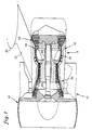
- ignitor guide 120 comprises a generally cylindrical sleeve 125 having a canted outer end 130 which aligns with the combustor walls and terminating in a hollow, slotted and flanged base 135.
- base 135 comprises a flange 140 fixed to sleeve 125 at the outer end thereof as by welding or the like, flange 140 including a downturned outer edge 145.
- a slotted annular member 150 is attached to downturned edge 145 as by welding or the like and provides closure of the base.
- bushing 155 Received within base 135 is a bushing 155 having a flanged generally annular base 160 provided with a lug 165 having a pointed (boat-shaped) outer end attached to a peripheral portion of the lower face of base 160 as by welding or the like.
- bushing 155 is received within sleeve 125 and bushing base 160 is received within hollow sleeve base 135 such that the lug 165 is received within the slot in annular member 150.
- the bushing is slidable in an axial direction (with respect to engine 5).
- the registry of lug 165 with the slot in base 160 prevents the rotation of the bushing inside the sleeve and damage to the plug attendant with such bushing rotation. Movement of the bushing within the sleeve accommodates thermal growth for thermal stress relief during normal operation of the engine and also simplifies the assembly of the engine by enhancing the ease with which the ignitor plug is inserted through the combustor wall.
- the pointed end of lug 165 allows a slight degree of pivoting of the bushing with respect to the sleeve for added freedom of movement, particularly when the bushing and sleeve are aligned as in Fig. 6, without sacrificing the stability associated with the lug length illustrated herein.
- Damage to the plug due to vibration of the guide is also minimized by the expanse of the bushing which is, in height, approximately 1.67 to 2.67 times the width of base 160. This expanse not only more evenly distributes vibratory forces along the lateral surface of the ignitor plug, but tends to prevent the bushing from engaging in any rocking motion due to burner vibration.
- Bushing base 160 is, along opposed major surfaces thereof, received between, and is maintained in surface-to-surface contact with corresponding opposed major interior surfaces of the sleeve base. This further reduces any tendency of the bushing to rock back and forth in response to combustor vibration and the attendant damage to the lateral surface of the ignitor plug.
- a wear resistant coating thereon such as a known coating consisting essentially of a mixture of 75% chromium carbide and 25% of an 80% nickel and 20% chromium alloy, plasma sprayed on the surfaces.
- the ignitor plug guide is mounted to the combustor by attachment to wall 70 thereof as by welding or other appropriate diffusion bonding techniques as will be determined by the types of materials employed in the combustor wall and the guide.
- Those skilled in the art will recognize the combustor wall structure shown in Fig. 2 as being a FLOATWALLTM, double-walled construction which is disclosed in U.S. Patent No. 4,302,941 and employed in modern gas turbine aircraft engines manufactured by the Pratt & Whitney Division of the assignee of the present invention, United Technologies Corporation.
- Fig. 2 the combustor wall structure shown in Fig. 2 as being a FLOATWALLTM, double-walled construction which is disclosed in U.S. Patent No. 4,302,941 and employed in modern gas turbine aircraft engines manufactured by the Pratt & Whitney Division of the assignee of the present invention, United Technologies Corporation.
- the guide of the present invention may also be employed with a shingled or "DOUBLE PASS" combustor wall structure also employed in current gas turbine aircraft engines produced by the above-noted Pratt & Whitney Division of the assignee herein, United Technologies Corporation, and disclosed in U.S. Patent No. 4,302,941.
- ignitor plug guide of the present invention has been shown in a particular embodiment thereof, it will be appreciated that various modifications will suggest themselves to those skilled in the art.
- the canting of the end of sleeve 125 to conform to the angular orientation of the combustor wall can be varied in accordance with combustors of varying geometries.
Landscapes
- Engineering & Computer Science (AREA)
- Chemical & Material Sciences (AREA)
- Combustion & Propulsion (AREA)
- Mechanical Engineering (AREA)
- General Engineering & Computer Science (AREA)
- Turbine Rotor Nozzle Sealing (AREA)
Description
Claims (6)
- An ignitor plug guide (120) employed in the combustor (35) of a gas turbine engine (5), said guide (120) comprising a generally cylindrical sleeve (125) adapted for fixture to a wall (70) of said combustor (35) in registry with an aperture therein which receives said ignitor plug (105) therethrough;characterised in that said guide further comprises a bushing (155) received within said sleeve, which engages, along the interior thereof, a lateral surface of said ignitor plug;in that said sleeve (125) terminates in a hollow flanged base (135) having a slot;and in that said bushing has a flanged base (160) including a lug (165) received within said slot in said flanged sleeve base (135) to prevent relative rotation between said bushing and said sleeve and attendant damage to said ignitor plug therefrom.
- The guide of claim 1 characterised by said bushing base (160), along opposed major surfaces thereof being received between, and maintained in slidable surface-to-surface contact with corresponding opposed major interior surfaces of said hollow sleeve base (135).
- The guide of claim 2 characterised by said major surfaces of said bushing base (160) and said opposed major interior surfaces of said hollow sleeve (135) being hardened with a wear-resistant coating thereon.
- The guide of claim 3 characterised by said wear resistant coating consisting essentially of a mixture of chromium carbide and a nickel-chromium alloy.
- The guide of any preceding claim characterised by the ratio of the height of said bushing to the width of said flanged base thereof being between approximately 0.375 and 0.600.
- The guide of any preceding claim characterised by said lug (165) having a pointed outer end.
Applications Claiming Priority (3)
| Application Number | Priority Date | Filing Date | Title |
|---|---|---|---|
| US08/172,968 US5533330A (en) | 1993-12-27 | 1993-12-27 | Ignitor plug guide for a gas turbine engine combustor |
| US172968 | 1993-12-27 | ||
| PCT/US1994/014216 WO1995018336A1 (en) | 1993-12-27 | 1994-12-09 | Ignitor plug guide for a gas turbine engine combustor |
Publications (2)
| Publication Number | Publication Date |
|---|---|
| EP0737291A1 EP0737291A1 (en) | 1996-10-16 |
| EP0737291B1 true EP0737291B1 (en) | 1999-03-31 |
Family
ID=22629939
Family Applications (1)
| Application Number | Title | Priority Date | Filing Date |
|---|---|---|---|
| EP95907937A Expired - Lifetime EP0737291B1 (en) | 1993-12-27 | 1994-12-09 | Ignitor plug guide for a gas turbine engine combustor |
Country Status (5)
| Country | Link |
|---|---|
| US (1) | US5533330A (en) |
| EP (1) | EP0737291B1 (en) |
| JP (1) | JP3604143B2 (en) |
| DE (1) | DE69417586T2 (en) |
| WO (1) | WO1995018336A1 (en) |
Families Citing this family (14)
| Publication number | Priority date | Publication date | Assignee | Title |
|---|---|---|---|---|
| JP3426987B2 (en) | 1998-11-13 | 2003-07-14 | 三菱重工業株式会社 | Corrosion- and wear-resistant coating member for high temperature, manufacturing method, and gas turbine blade |
| US6334298B1 (en) * | 2000-07-14 | 2002-01-01 | General Electric Company | Gas turbine combustor having dome-to-liner joint |
| DE10055275A1 (en) * | 2000-11-08 | 2002-05-23 | Iropa Ag | Endless thread brake band and process for its manufacture |
| US7134286B2 (en) * | 2004-08-24 | 2006-11-14 | Pratt & Whitney Canada Corp. | Gas turbine floating collar arrangement |
| US7690207B2 (en) * | 2004-08-24 | 2010-04-06 | Pratt & Whitney Canada Corp. | Gas turbine floating collar arrangement |
| US20070087129A1 (en) * | 2005-10-19 | 2007-04-19 | Blankenship Donn R | Methods for repairing a workpiece |
| FR2886714B1 (en) * | 2005-06-07 | 2007-09-07 | Snecma Moteurs Sa | ANTI-ROTARY INJECTION SYSTEM FOR TURBO-REACTOR |
| US7721522B2 (en) * | 2006-01-05 | 2010-05-25 | United Technologies Corporation | Torque load transfer attachment hardware |
| US7476111B2 (en) * | 2007-05-17 | 2009-01-13 | United Technologies Corporation | Two-plug electrical outlet with dual voltage |
| US20090260340A1 (en) * | 2008-04-17 | 2009-10-22 | General Electric Company | Combustor of a Turbine, a Method of Retro-Fitting a Combustor of a Turbine and a Method of Building a Combustor of a Turbine |
| FR3026827B1 (en) * | 2014-10-01 | 2019-06-07 | Safran Aircraft Engines | TURBOMACHINE COMBUSTION CHAMBER |
| GB2548585B (en) * | 2016-03-22 | 2020-05-27 | Rolls Royce Plc | A combustion chamber assembly |
| US10669944B2 (en) | 2016-11-16 | 2020-06-02 | General Electric Company | Cooling shrouds |
| US11486581B2 (en) * | 2020-09-29 | 2022-11-01 | Pratt & Whitney Canada Corp. | Fuel nozzle and associated method of assembly |
Family Cites Families (13)
| Publication number | Priority date | Publication date | Assignee | Title |
|---|---|---|---|---|
| US2941363A (en) * | 1955-04-11 | 1960-06-21 | Bendix Aviat Corp | Dual baffled igniter for combustion chamber |
| US3025425A (en) * | 1958-04-21 | 1962-03-13 | Bendix Corp | Electrical discharge device |
| US3116606A (en) * | 1958-07-21 | 1964-01-07 | Gen Motors Corp | Combustion can support |
| US3572733A (en) * | 1969-01-02 | 1971-03-30 | Gen Electric | Shaft seal used in gas turbine engines |
| US3721089A (en) * | 1971-06-08 | 1973-03-20 | United Aircraft Corp | Crossover tube construction |
| CA992755A (en) * | 1972-10-02 | 1976-07-13 | General Electric Company | Gas turbine engine igniter assembly |
| US4124737A (en) * | 1976-12-30 | 1978-11-07 | Union Carbide Corporation | High temperature wear resistant coating composition |
| GB1602836A (en) * | 1977-05-11 | 1981-11-18 | Lucas Industries Ltd | Sealing arrangement for use in a combustion assembly |
| US4302941A (en) * | 1980-04-02 | 1981-12-01 | United Technologies Corporation | Combuster liner construction for gas turbine engine |
| US4380906A (en) * | 1981-01-22 | 1983-04-26 | United Technologies Corporation | Combustion liner cooling scheme |
| US4712370A (en) * | 1986-04-24 | 1987-12-15 | The United States Of America As Represented By The Secretary Of The Air Force | Sliding duct seal |
| FR2639095B1 (en) * | 1988-11-17 | 1990-12-21 | Snecma | COMBUSTION CHAMBER OF A TURBOMACHINE WITH FLOATING MOUNTS PREVAPORIZATION BOWLS |
| US5117624A (en) * | 1990-09-17 | 1992-06-02 | General Electric Company | Fuel injector nozzle support |
-
1993
- 1993-12-27 US US08/172,968 patent/US5533330A/en not_active Expired - Lifetime
-
1994
- 1994-12-09 JP JP51805395A patent/JP3604143B2/en not_active Expired - Fee Related
- 1994-12-09 DE DE69417586T patent/DE69417586T2/en not_active Expired - Lifetime
- 1994-12-09 EP EP95907937A patent/EP0737291B1/en not_active Expired - Lifetime
- 1994-12-09 WO PCT/US1994/014216 patent/WO1995018336A1/en not_active Ceased
Also Published As
| Publication number | Publication date |
|---|---|
| US5533330A (en) | 1996-07-09 |
| JP3604143B2 (en) | 2004-12-22 |
| JPH09507280A (en) | 1997-07-22 |
| DE69417586T2 (en) | 1999-10-28 |
| DE69417586D1 (en) | 1999-05-06 |
| WO1995018336A1 (en) | 1995-07-06 |
| EP0737291A1 (en) | 1996-10-16 |
Similar Documents
| Publication | Publication Date | Title |
|---|---|---|
| US5533330A (en) | Ignitor plug guide for a gas turbine engine combustor | |
| US6098407A (en) | Premixing fuel injector with improved secondary fuel-air injection | |
| EP1111219B1 (en) | Mounting an igniter in an augmenter | |
| EP0799399B1 (en) | LOW NOx FUEL NOZZLE ASSEMBLY | |
| US3931707A (en) | Augmentor flameholding apparatus | |
| EP0078630B1 (en) | Fuel nozzle assembly for a gas turbine engine | |
| US7827797B2 (en) | Injection assembly for a combustor | |
| US8434292B2 (en) | Ceramic-encased hot surface igniter system for jet engines | |
| EP1400754B1 (en) | Premixed pilot burner for a combustion turbine engine | |
| US6351949B1 (en) | Interchangeable combustor chute | |
| US10041676B2 (en) | Sealed conical-flat dome for flight engine combustors | |
| US5117624A (en) | Fuel injector nozzle support | |
| US5511940A (en) | Ceramic turbine nozzle | |
| US7596949B2 (en) | Method and apparatus for heat shielding gas turbine engines | |
| US5463864A (en) | Fuel nozzle guide for a gas turbine engine combustor | |
| US5207054A (en) | Small diameter gas turbine engine | |
| EP0192266A2 (en) | Gas turbine combustor | |
| US6401447B1 (en) | Combustor apparatus for a gas turbine engine | |
| US12313264B2 (en) | Coupling assembly for a turbine engine | |
| EP1671065B1 (en) | Auxiliary power unit having a rotary fuel slinger | |
| US4712371A (en) | Process and device for starting a gas turbine | |
| EP2053313A2 (en) | Combustors with igniters having protrusions | |
| US7360364B2 (en) | Method and apparatus for assembling gas turbine engine combustors | |
| KR102340331B1 (en) | Corss flame module, combustor, and gas turbine including the same | |
| US5269138A (en) | Variable geometry flame trap device for use in an after-burner device of a gas turbine |
Legal Events
| Date | Code | Title | Description |
|---|---|---|---|
| PUAI | Public reference made under article 153(3) epc to a published international application that has entered the european phase |
Free format text: ORIGINAL CODE: 0009012 |
|
| 17P | Request for examination filed |
Effective date: 19960726 |
|
| AK | Designated contracting states |
Kind code of ref document: A1 Designated state(s): DE FR GB |
|
| 17Q | First examination report despatched |
Effective date: 19970717 |
|
| GRAG | Despatch of communication of intention to grant |
Free format text: ORIGINAL CODE: EPIDOS AGRA |
|
| GRAG | Despatch of communication of intention to grant |
Free format text: ORIGINAL CODE: EPIDOS AGRA |
|
| GRAH | Despatch of communication of intention to grant a patent |
Free format text: ORIGINAL CODE: EPIDOS IGRA |
|
| GRAH | Despatch of communication of intention to grant a patent |
Free format text: ORIGINAL CODE: EPIDOS IGRA |
|
| GRAA | (expected) grant |
Free format text: ORIGINAL CODE: 0009210 |
|
| AK | Designated contracting states |
Kind code of ref document: B1 Designated state(s): DE FR GB |
|
| ET | Fr: translation filed | ||
| REF | Corresponds to: |
Ref document number: 69417586 Country of ref document: DE Date of ref document: 19990506 |
|
| PLBE | No opposition filed within time limit |
Free format text: ORIGINAL CODE: 0009261 |
|
| STAA | Information on the status of an ep patent application or granted ep patent |
Free format text: STATUS: NO OPPOSITION FILED WITHIN TIME LIMIT |
|
| 26N | No opposition filed | ||
| REG | Reference to a national code |
Ref country code: GB Ref legal event code: IF02 |
|
| PGFP | Annual fee paid to national office [announced via postgrant information from national office to epo] |
Ref country code: FR Payment date: 20081205 Year of fee payment: 15 |
|
| REG | Reference to a national code |
Ref country code: FR Ref legal event code: ST Effective date: 20100831 |
|
| PG25 | Lapsed in a contracting state [announced via postgrant information from national office to epo] |
Ref country code: FR Free format text: LAPSE BECAUSE OF NON-PAYMENT OF DUE FEES Effective date: 20091231 |
|
| PGFP | Annual fee paid to national office [announced via postgrant information from national office to epo] |
Ref country code: GB Payment date: 20131204 Year of fee payment: 20 Ref country code: DE Payment date: 20131204 Year of fee payment: 20 |
|
| REG | Reference to a national code |
Ref country code: DE Ref legal event code: R071 Ref document number: 69417586 Country of ref document: DE |
|
| REG | Reference to a national code |
Ref country code: DE Ref legal event code: R071 Ref document number: 69417586 Country of ref document: DE |
|
| REG | Reference to a national code |
Ref country code: GB Ref legal event code: PE20 Expiry date: 20141208 |
|
| PG25 | Lapsed in a contracting state [announced via postgrant information from national office to epo] |
Ref country code: GB Free format text: LAPSE BECAUSE OF EXPIRATION OF PROTECTION Effective date: 20141208 |