EP0737012A2 - Method for segmenting and estimating a moving object motion - Google Patents
Method for segmenting and estimating a moving object motion Download PDFInfo
- Publication number
- EP0737012A2 EP0737012A2 EP95111194A EP95111194A EP0737012A2 EP 0737012 A2 EP0737012 A2 EP 0737012A2 EP 95111194 A EP95111194 A EP 95111194A EP 95111194 A EP95111194 A EP 95111194A EP 0737012 A2 EP0737012 A2 EP 0737012A2
- Authority
- EP
- European Patent Office
- Prior art keywords
- motion
- revised
- values
- motion vector
- region
- Prior art date
- Legal status (The legal status is an assumption and is not a legal conclusion. Google has not performed a legal analysis and makes no representation as to the accuracy of the status listed.)
- Granted
Links
- 238000000034 method Methods 0.000 title claims abstract description 24
- 239000013598 vector Substances 0.000 claims abstract description 39
- 238000003786 synthesis reaction Methods 0.000 claims abstract description 6
- 238000001514 detection method Methods 0.000 description 6
- 238000013507 mapping Methods 0.000 description 5
- 238000010586 diagram Methods 0.000 description 2
- 238000006073 displacement reaction Methods 0.000 description 2
- 230000011218 segmentation Effects 0.000 description 2
- 238000012935 Averaging Methods 0.000 description 1
- 238000004458 analytical method Methods 0.000 description 1
- 238000013459 approach Methods 0.000 description 1
- 230000005540 biological transmission Effects 0.000 description 1
- 238000013144 data compression Methods 0.000 description 1
- 238000003709 image segmentation Methods 0.000 description 1
- 238000005259 measurement Methods 0.000 description 1
- 238000012986 modification Methods 0.000 description 1
- 230000004048 modification Effects 0.000 description 1
- 230000003287 optical effect Effects 0.000 description 1
- 238000012545 processing Methods 0.000 description 1
Images

Classifications
-
- H—ELECTRICITY
- H04—ELECTRIC COMMUNICATION TECHNIQUE
- H04N—PICTORIAL COMMUNICATION, e.g. TELEVISION
- H04N19/00—Methods or arrangements for coding, decoding, compressing or decompressing digital video signals
- H04N19/50—Methods or arrangements for coding, decoding, compressing or decompressing digital video signals using predictive coding
- H04N19/503—Methods or arrangements for coding, decoding, compressing or decompressing digital video signals using predictive coding involving temporal prediction
- H04N19/51—Motion estimation or motion compensation
- H04N19/537—Motion estimation other than block-based
- H04N19/543—Motion estimation other than block-based using regions
-
- H—ELECTRICITY
- H04—ELECTRIC COMMUNICATION TECHNIQUE
- H04N—PICTORIAL COMMUNICATION, e.g. TELEVISION
- H04N19/00—Methods or arrangements for coding, decoding, compressing or decompressing digital video signals
- H04N19/20—Methods or arrangements for coding, decoding, compressing or decompressing digital video signals using video object coding
Definitions
- the present invention relates to an objected-oriented analysis-synthesis coding technique for encoding image signals; and, more particularly, to a method for segmenting an image according to moving objects therein and estimating each motion of the moving objects.
- a large amount of digital data is needed to define each video frame signal since a video line signal in the video frame signal comprises a sequence of digital data referred to as pixel values. Since, however, the available frequency bandwidth of a conventional transmission channel is limited, in order to transmit the large amount of digital data therethrough, it is inevitable to compress or reduce the volume of data through the use of a data compression technique, especially in the case of such low bit-rate video signal encoder as video-telephone or teleconference system.
- One of such methods for encoding video signals for a low bit-rate encoding system is the so-called object-oriented analysis-synthesis coding technique, wherein an input video image containing moving objects therein is divided according to the moving objects; and each object is described by three sets of parameters defining the motion, contour(or shape) and pixel data of the object.
- an area of the input video image to be segmented is defined by a set of uniform motion and position parameters denoted as mapping parameters. For instance, eight parameters are used to describe an arbitrary three-dimensional motion of a planar rigid object.
- a change detector distinguishes between temporally changed and unchanged regions of two successive fields. Each changed image region is interpreted as one object. The motion and position of each object is described by one set of mapping parameters. Based on the mapping parameters and the information on a temporally preceding field, reconstruction of a temporally ensuing field can be achieved.
- a primary object of the invention to provide an improved method for exactly segmenting an image according to the moving objects therein and precisely estimating each motion of the moving objects.
- a method for use in an object-oriented analysis-synthesis coder, for segmenting an image of a current frame into moving objects and describing each motion of the moving objects with a set of motion parameters, which comprises the steps of:
- Fig. 1 describes a block diagram of segmenting moving objects and describing each motion of the moving objects with a set of motion parameters in accordance with the present invention.
- two input signals i.e., a current frame signal and a reconstructed previous frame signal are fed to a change detector 100 and a motion estimator 102, respectively.
- the change detector 100 compares the current frame signal with the reconstructed previous frame signal to detect a changed area from the background in the current frame.
- the detected changed area information is sent to the motion estimator 102 and a motion vector field detector 103.
- the motion estimator 102 detects motion vectors for a set of selected pixels, i.e., feature points, in the changed area, wherein each of the feature points is a pixel capable of representing its neighboring pixels. That is, a number of feature points are first selected from all of the pixels contained in the changed area. Then, motion vectors for each of the selected feature points are determined by forming a block of a predetermined size at each of the selected feature points and by using a block matching algorithm( see , e.g., J. R. Jain et al., "Displacement Measurement and Its Application in Interframe Image Coding", IEEE Transactions on Communications , COM-29 , No. 12 pp 1799-1808(December 1981)), wherein each of the motion vectors represents a spatial displacement between one feature point in the current frame and a corresponding matching point, i.e., a most similar pixel, in the reconstructed previous frame.
- a block matching algorithm see e.g., J. R. Jain
- the motion vector field detector 103 determines motion vectors for non-feature points in the changed area by averaging the motion vectors for the feature points, to thereby detect motion vectors for all of the pixels in the changed area.
- the changed area defined by motion vectors for all of the pixels therein is called a motion vector field.
- the information on the motion vector field is sent to a seed block detection and region growing circuit 104.
- the seed block detection and region growing circuit 104 segments the motion vector field into moving objects and describes each motion of the moving objects with a set of motion parameters.
- an 8-parameter motion model see , e.g., Gilad Adiv, "Determining Three-Dimensional Motion and Structure from Optical Flow Generated by Several Moving Objects", IEEE Transactions on Patent Analysis and Machine Intelligence , PAMI-7, No. 4, pp 384-401(July 1985)), which may be represented as follows: Eq.
- V x (x,y) a 1 + a 2 x + a 3 y + a 7 x 2 + a 8 xy
- V y (x,y) a 4 + a 5 x + a 6 y + a 7 xy + a 8 y 2
- V x (x,y) is the horizontal component of a motion vector at a position (x,y)
- V y (x,y) is the vertical component of the motion vector at the position (x,y).
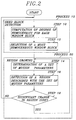
- the eight motion parameters for each of the moving objects in the motion vector field are determined through two processes: a seed block detection process 10 and a region growing process 20.
- the seed block detection process 10 detects a seed block in order to determine a set of initial values for the eight motion parameters, and the region growing process 20 increases the size of the seed block through the use of an iterative region growing algorithm, to thereby estimate a set of actual values for the eight motion parameters.
- step 10 a W x W pixel size of window block slides on the motion vector field; and the degree of homogeneity for each position of the window block is computed. Thereafter, in the step 12, a most homogeneous window block is selected as a seed block.
- V ⁇ y ( x , y ) a 4 + a 5 x + a 6 y + a 7 xy + a 8 y 2
- D(m,n) represents the degree of homogeneity at a window position (m,n)
- W is a window size
- ⁇ a 1 *, a 2 *, ..., a 8 * ⁇ is an optimal set of motion parameters for a window block.
- the optimal set of motion parameters is a solution for a set of eight equations, each of which is derived by taking partial derivatives of Eq. (4) with respect to a 1 , a 2 , ..., a 8 and equating them to 0.
- the degree of homogeneity for a window block is determined through the use of an error function between a given set of motion vectors in a window block and an estimated set of motion vectors obtained from the optimal set of motion parameters.
- the process 20 After detecting the seed block, the process 20 begins to determine a set of initial values for a set of motion parameters. And then, in order to correct the initial values to an actual set of motion parameters, a convergence process is taken through the use of a region growing technique described below.
- step 14 a set of initial values for a set of motion parameters is determined based on the seed block detected in step 12 or a set of revised values for the set of motion parameters is determined based on a revised region detected in step 16 below.
- the set of initial values for the set of motion parameters are determined by fetching the optimal set of motion parameters for the seed block. And, the set of revised values for the set of motion parameters is determined based on all of the motion vectors contained in the revised region as in the case of detecting the optimal set of motion vectors for the seed block.
- step 16 in order to correct the initial values or the revised values to an actual set of motion parameters, a region growing process is carried out by evaluating whether each motion vector contained in and around the seed block or the revised region is capable of being described or not with the initial values or the revised values, to thereby detect the revised region or define a newly revised region.
- step 18 the difference between a current revised region and a previous revised region is compared with a predetermined value, to decide whether a region growing iteration is to be continued.
- the region growing iteration is repeated until the difference between the current revised region and the previous revised region is less than the predetermined value, to thereby determine a set of final values for the set of motion parameters.
- Another set of motion parameters is detected by repeating the steps 10 to 18 until each set of motion parameters for each of the moving objects is determined.
Landscapes
- Engineering & Computer Science (AREA)
- Multimedia (AREA)
- Signal Processing (AREA)
- Compression Or Coding Systems Of Tv Signals (AREA)
- Image Analysis (AREA)
Abstract
Description
- The present invention relates to an objected-oriented analysis-synthesis coding technique for encoding image signals; and, more particularly, to a method for segmenting an image according to moving objects therein and estimating each motion of the moving objects.
- In digital television systems such as video-telephone, teleconference and high definition television systems, a large amount of digital data is needed to define each video frame signal since a video line signal in the video frame signal comprises a sequence of digital data referred to as pixel values. Since, however, the available frequency bandwidth of a conventional transmission channel is limited, in order to transmit the large amount of digital data therethrough, it is inevitable to compress or reduce the volume of data through the use of a data compression technique, especially in the case of such low bit-rate video signal encoder as video-telephone or teleconference system.
- One of such methods for encoding video signals for a low bit-rate encoding system is the so-called object-oriented analysis-synthesis coding technique, wherein an input video image containing moving objects therein is divided according to the moving objects; and each object is described by three sets of parameters defining the motion, contour(or shape) and pixel data of the object.
- In order to achieve the primary goal of the object-oriented analysis-synthesis coding technique, i.e., the task of exactly dividing the input video image into the moving objects and precisely estimating each motion of the moving objects, there have been proposed several approaches. One of them is a hierarchically structured segmentation technique(see Michael Hotter et al., "Image Segmentation Based on Object Oriented Mapping Parameter Estimation", Signal Processing, 15, No. 3, pp 315-334(October 1988)).
- According to the hierarchically structured segmentation technique, an area of the input video image to be segmented is defined by a set of uniform motion and position parameters denoted as mapping parameters. For instance, eight parameters are used to describe an arbitrary three-dimensional motion of a planar rigid object. In a first step, a change detector distinguishes between temporally changed and unchanged regions of two successive fields. Each changed image region is interpreted as one object. The motion and position of each object is described by one set of mapping parameters. Based on the mapping parameters and the information on a temporally preceding field, reconstruction of a temporally ensuing field can be achieved. In a next step of hierarchy, those regions of the image, which are not correctly described in their mapping, are again detected by the change detector and treated according to the changed parts detected at the first step of hierarchy. However, in this technique, if a large number of moving objects is included within one changed area, it may be difficult to properly segment them.
- It is, therefore, a primary object of the invention to provide an improved method for exactly segmenting an image according to the moving objects therein and precisely estimating each motion of the moving objects.
- In accordance with the invention, there is provided a method, for use in an object-oriented analysis-synthesis coder, for segmenting an image of a current frame into moving objects and describing each motion of the moving objects with a set of motion parameters, which comprises the steps of:
- (a) comparing the current frame with a preceding frame to detect a moving area in the current frame;
- (b) further comparing the current frame with the preceding frame to detect a motion vector for each pixel in the moving area, to thereby produce a motion vector field;
- (c) sliding window blocks of an N x N pixel size on the motion vector field, N being a positive integer, and computing the degree of homogeneity for each of the window blocks to select a most homogeneous window block as seed block;
- (d) determining a set of initial values for the set of motion parameters based on the seed block;
- (e) evaluating whether each motion vector contained in and around the seed block is describable with the set of initial values or not, to thereby detect a revised region defined by motion vectors described with the set of initial values;
- (f) determining a set of revised values for the set of motion parameters from the revised region;
- (g) evaluating whether each motion vector contained in and around the revised region is describable with the set of revised values or not, to thereby detect a newly revised region defined by motion vectors described with the set of revised values;
- (h) repeating the steps (f) and (g) until the difference between a current revised region and a previous revised region is less than a predetermined value, to thereby determine a set of final values for the set of motion parameters; and
- (i) repeating the steps (c) to (h) until each set of motion parameters for each of the moving objects is determined.
- The above and other objects and features of the present invention will become apparent from the following description of preferred embodiments given in conjunction with the accompanying drawings, in which:
- Fig. 1 is a block diagram of segmenting an image into moving objects and describing each motion of the moving objects with a set of motion parameters in accordance with the present invention; and
- Fig. 2 shows a flow chart illustrating an operational flow of the seed block detection and region growing circuit shown in Fig. 1.
- Fig. 1 describes a block diagram of segmenting moving objects and describing each motion of the moving objects with a set of motion parameters in accordance with the present invention.
- As shown in Fig. 1, two input signals, i.e., a current frame signal and a reconstructed previous frame signal are fed to a change detector 100 and a
motion estimator 102, respectively. - The change detector 100 compares the current frame signal with the reconstructed previous frame signal to detect a changed area from the background in the current frame. The detected changed area information is sent to the
motion estimator 102 and a motionvector field detector 103. - The
motion estimator 102 detects motion vectors for a set of selected pixels, i.e., feature points, in the changed area, wherein each of the feature points is a pixel capable of representing its neighboring pixels. That is, a number of feature points are first selected from all of the pixels contained in the changed area. Then, motion vectors for each of the selected feature points are determined by forming a block of a predetermined size at each of the selected feature points and by using a block matching algorithm(see, e.g., J. R. Jain et al., "Displacement Measurement and Its Application in Interframe Image Coding", IEEE Transactions on Communications, COM-29, No. 12 pp 1799-1808(December 1981)), wherein each of the motion vectors represents a spatial displacement between one feature point in the current frame and a corresponding matching point, i.e., a most similar pixel, in the reconstructed previous frame. - The motion
vector field detector 103 determines motion vectors for non-feature points in the changed area by averaging the motion vectors for the feature points, to thereby detect motion vectors for all of the pixels in the changed area. The changed area defined by motion vectors for all of the pixels therein is called a motion vector field. The information on the motion vector field is sent to a seed block detection and region growing circuit 104. - The seed block detection and region growing circuit 104 segments the motion vector field into moving objects and describes each motion of the moving objects with a set of motion parameters. In accordance with the present invention, in order to describe each motion of the moving objects, there is employed an 8-parameter motion model(see, e.g., Gilad Adiv, "Determining Three-Dimensional Motion and Structure from Optical Flow Generated by Several Moving Objects", IEEE Transactions on Patent Analysis and Machine Intelligence, PAMI-7, No. 4, pp 384-401(July 1985)), which may be represented as follows:

- Referring to Fig. 2, the eight motion parameters for each of the moving objects in the motion vector field are determined through two processes: a seed
block detection process 10 and aregion growing process 20. - The seed
block detection process 10 detects a seed block in order to determine a set of initial values for the eight motion parameters, and theregion growing process 20 increases the size of the seed block through the use of an iterative region growing algorithm, to thereby estimate a set of actual values for the eight motion parameters. - In the seed
block detection process 10, there are twosteps step 10, a W x W pixel size of window block slides on the motion vector field; and the degree of homogeneity for each position of the window block is computed. Thereafter, in thestep 12, a most homogeneous window block is selected as a seed block. The degree of homogeneity may be determined as follows: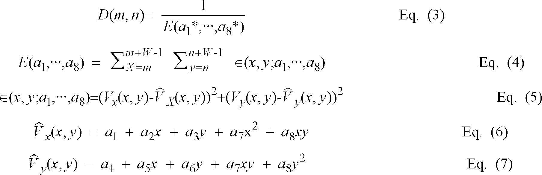
- After detecting the seed block, the
process 20 begins to determine a set of initial values for a set of motion parameters. And then, in order to correct the initial values to an actual set of motion parameters, a convergence process is taken through the use of a region growing technique described below. - In
step 14, a set of initial values for a set of motion parameters is determined based on the seed block detected instep 12 or a set of revised values for the set of motion parameters is determined based on a revised region detected instep 16 below. - The set of initial values for the set of motion parameters are determined by fetching the optimal set of motion parameters for the seed block. And, the set of revised values for the set of motion parameters is determined based on all of the motion vectors contained in the revised region as in the case of detecting the optimal set of motion vectors for the seed block.
- In
step 16, in order to correct the initial values or the revised values to an actual set of motion parameters, a region growing process is carried out by evaluating whether each motion vector contained in and around the seed block or the revised region is capable of being described or not with the initial values or the revised values, to thereby detect the revised region or define a newly revised region. - In
step 18, the difference between a current revised region and a previous revised region is compared with a predetermined value, to decide whether a region growing iteration is to be continued. The region growing iteration is repeated until the difference between the current revised region and the previous revised region is less than the predetermined value, to thereby determine a set of final values for the set of motion parameters. - After detecting the final values for the set of motion parameters, another set of motion parameters is detected by repeating the
steps 10 to 18 until each set of motion parameters for each of the moving objects is determined. - While the present invention has been shown and described with respect to the particular embodiments, it will be apparent to those skilled in the art that many changes and modifications may be made without departing from the spirit and scope of the invention as defined in the appended claims.
Claims (1)
- A method, for use in an object-oriented analysis-synthesis coder, for segmenting an image, said image containing moving objects, of a current frame into the moving objects therein and describing each motion of the moving objects with a set of motion parameters, which comprises the steps of:(a) comparing the current frame with a preceding frame to detect a moving area in the current frame;(b) further comparing the current frame with the preceding frame to detect a motion vector for each pixel in the moving area, to thereby produce a motion vector field;(c) sliding window blocks of an N x N pixel size on the motion vector field, N being a positive integer, and computing the degree of homogeneity for each of the window blocks to select a most homogeneous window block as a seed block;(d) determining a set of initial values for the set of motion parameters based on the seed block;(e) evaluating whether each motion vector contained in and around the seed block is describable with the set of initial values or not, to thereby detect a revised region defined by motion vectors described with the set of initial values;(f) determining a set of revised values for the set of motion parameters from the revised region;(g) evaluating whether each motion vector contained in and around the revised region is describable with the set of revised values or not, to thereby detect a newly revised region defined by motion vectors described with the set of revised values;(h) repeating the steps (f) and (g) until the difference between a current revised region and a previous revised region is less than a predetermined value, to thereby determine a set of final values for the set of motion parameters; and(i) repeating the steps (c) to (h) until each set of motion parameters for each of the moving objects is determined.
Applications Claiming Priority (2)
| Application Number | Priority Date | Filing Date | Title |
|---|---|---|---|
| KR9508177 | 1995-04-08 | ||
| KR1019950008177A KR0181036B1 (en) | 1995-04-08 | 1995-04-08 | Method for segmenting an image into moving objects and estimating each moving object motion |
Publications (3)
| Publication Number | Publication Date |
|---|---|
| EP0737012A2 true EP0737012A2 (en) | 1996-10-09 |
| EP0737012A3 EP0737012A3 (en) | 1998-03-11 |
| EP0737012B1 EP0737012B1 (en) | 2001-10-24 |
Family
ID=19411780
Family Applications (1)
| Application Number | Title | Priority Date | Filing Date |
|---|---|---|---|
| EP19950111194 Expired - Lifetime EP0737012B1 (en) | 1995-04-08 | 1995-07-17 | Method for segmenting and estimating a moving object motion |
Country Status (6)
| Country | Link |
|---|---|
| US (1) | US5748761A (en) |
| EP (1) | EP0737012B1 (en) |
| JP (1) | JP3881709B2 (en) |
| KR (1) | KR0181036B1 (en) |
| CN (1) | CN1107415C (en) |
| DE (1) | DE69523441T2 (en) |
Cited By (2)
| Publication number | Priority date | Publication date | Assignee | Title |
|---|---|---|---|---|
| WO1997046022A3 (en) * | 1996-05-24 | 1998-02-05 | Philips Electronics Nv | Motion estimation |
| WO1998035501A3 (en) * | 1997-02-06 | 1998-11-05 | Koninkl Philips Electronics Nv | Image segmentation and object tracking method and corresponding system |
Families Citing this family (32)
| Publication number | Priority date | Publication date | Assignee | Title |
|---|---|---|---|---|
| US6832002B2 (en) * | 1997-02-10 | 2004-12-14 | Definiens Ag | Method of iterative segmentation of a digital picture |
| KR100234264B1 (en) * | 1997-04-15 | 1999-12-15 | 윤종용 | Block matching method using moving target window |
| JP3384314B2 (en) * | 1997-12-02 | 2003-03-10 | ヤマハ株式会社 | Tone response image generation system, method, apparatus, and recording medium therefor |
| US7031517B1 (en) | 1998-10-02 | 2006-04-18 | Canon Kabushiki Kaisha | Method and apparatus for segmenting images |
| AU735807B2 (en) * | 1998-10-02 | 2001-07-19 | Canon Kabushiki Kaisha | Segmenting moving objects and determining their motion |
| US6766037B1 (en) * | 1998-10-02 | 2004-07-20 | Canon Kabushiki Kaisha | Segmenting moving objects and determining their motion |
| AU746669B2 (en) * | 1998-10-02 | 2002-05-02 | Canon Kabushiki Kaisha | Method and apparatus for segmenting images |
| FR2790852B1 (en) * | 1999-03-08 | 2001-04-20 | Thomson Multimedia Sa | METHOD FOR EVALUATING ENCODED IMAGES, DEVICE IMPLEMENTING THE METHOD AND USE OF THE DEVICE AND METHOD |
| US6289052B1 (en) * | 1999-06-07 | 2001-09-11 | Lucent Technologies Inc. | Methods and apparatus for motion estimation using causal templates |
| AU763919B2 (en) * | 2000-03-16 | 2003-08-07 | Canon Kabushiki Kaisha | Tracking objects from video sequences |
| US6665450B1 (en) | 2000-09-08 | 2003-12-16 | Avid Technology, Inc. | Interpolation of a sequence of images using motion analysis |
| US7545957B2 (en) * | 2001-04-20 | 2009-06-09 | Avid Technology, Inc. | Analyzing motion of characteristics in images |
| US7043058B2 (en) * | 2001-04-20 | 2006-05-09 | Avid Technology, Inc. | Correcting motion vector maps for image processing |
| US6806876B2 (en) * | 2001-07-11 | 2004-10-19 | Micron Technology, Inc. | Three dimensional rendering including motion sorting |
| WO2003067868A2 (en) * | 2002-02-06 | 2003-08-14 | Koninklijke Philips Electronics N.V. | Unit for and method of segmentation |
| US7194676B2 (en) | 2002-03-01 | 2007-03-20 | Avid Technology, Inc. | Performance retiming effects on synchronized data in an editing system |
| US6983020B2 (en) * | 2002-03-25 | 2006-01-03 | Citrix Online Llc | Method and apparatus for fast block motion detection |
| US6863220B2 (en) * | 2002-12-31 | 2005-03-08 | Massachusetts Institute Of Technology | Manually operated switch for enabling and disabling an RFID card |
| GB2409029A (en) * | 2003-12-11 | 2005-06-15 | Sony Uk Ltd | Face detection |
| TWI255136B (en) * | 2004-04-02 | 2006-05-11 | Mstar Semiconductor Inc | De-interlacing module and related method capable of adaptively de-interlacing a video field |
| CN100420299C (en) * | 2004-12-24 | 2008-09-17 | 北京中星微电子有限公司 | A screen broadcasting method |
| CN100393133C (en) * | 2004-12-30 | 2008-06-04 | 中兴通讯股份有限公司 | A Segmentation Method of Moving Objects in Video Sequence |
| US7522749B2 (en) * | 2005-04-08 | 2009-04-21 | Microsoft Corporation | Simultaneous optical flow estimation and image segmentation |
| US7747075B2 (en) * | 2005-06-20 | 2010-06-29 | International Business Machines Corporation | Salient motion detection system, method and program product therefor |
| CN101087413B (en) * | 2006-06-07 | 2010-05-12 | 中兴通讯股份有限公司 | Segmentation Method of Moving Objects in Video Sequence |
| US7783118B2 (en) * | 2006-07-13 | 2010-08-24 | Seiko Epson Corporation | Method and apparatus for determining motion in images |
| JP4955616B2 (en) * | 2008-06-27 | 2012-06-20 | 富士フイルム株式会社 | Image processing apparatus, image processing method, and image processing program |
| US8848802B2 (en) | 2009-09-04 | 2014-09-30 | Stmicroelectronics International N.V. | System and method for object based parametric video coding |
| US9626769B2 (en) * | 2009-09-04 | 2017-04-18 | Stmicroelectronics International N.V. | Digital video encoder system, method, and non-transitory computer-readable medium for tracking object regions |
| US10178396B2 (en) * | 2009-09-04 | 2019-01-08 | Stmicroelectronics International N.V. | Object tracking |
| CN103942544B (en) * | 2009-12-22 | 2017-11-28 | 松下电器产业株式会社 | Act resolver |
| KR20150116260A (en) | 2014-04-07 | 2015-10-15 | 삼성전자주식회사 | Method for marker tracking and an electronic device thereof |
Family Cites Families (6)
| Publication number | Priority date | Publication date | Assignee | Title |
|---|---|---|---|---|
| JP2586686B2 (en) * | 1990-04-19 | 1997-03-05 | 日本電気株式会社 | Motion picture motion information detecting apparatus and motion compensation inter-frame predictive coding apparatus for moving picture |
| GB9019538D0 (en) * | 1990-09-07 | 1990-10-24 | Philips Electronic Associated | Tracking a moving object |
| GB9215102D0 (en) * | 1992-07-16 | 1992-08-26 | Philips Electronics Uk Ltd | Tracking moving objects |
| JP3679426B2 (en) * | 1993-03-15 | 2005-08-03 | マサチューセッツ・インスティチュート・オブ・テクノロジー | A system that encodes image data into multiple layers, each representing a coherent region of motion, and motion parameters associated with the layers. |
| FR2703802A1 (en) * | 1993-04-07 | 1994-10-14 | Philips Electronique Lab | Apparatus for motion estimation between successive images of an animated image sequence subdivided into two-dimensional blocks of pixels. |
| JP2576771B2 (en) * | 1993-09-28 | 1997-01-29 | 日本電気株式会社 | Motion compensation prediction device |
-
1995
- 1995-04-08 KR KR1019950008177A patent/KR0181036B1/en not_active Expired - Lifetime
- 1995-07-13 US US08/502,229 patent/US5748761A/en not_active Expired - Lifetime
- 1995-07-17 JP JP20286695A patent/JP3881709B2/en not_active Expired - Lifetime
- 1995-07-17 EP EP19950111194 patent/EP0737012B1/en not_active Expired - Lifetime
- 1995-07-17 DE DE69523441T patent/DE69523441T2/en not_active Expired - Lifetime
- 1995-07-21 CN CN95109996A patent/CN1107415C/en not_active Expired - Lifetime
Non-Patent Citations (3)
| Title |
|---|
| GILAD ADIV: "Determining Three-Dimensional Motion and Structure from Optical Flow Generated by Several Moving Objects", IEEE TRANSACTIONS ON PATENT ANALYSIS AND MACHINE INTELLIGENCE, vol. PAMI-7, no. 4, July 1985 (1985-07-01), pages 384 - 401, XP011242853 |
| J.R.JAIN ET AL.: "Displacement Measurement and Its Application in Interframe Image Coding", IEEE TRANSACTIONS ON COMMUNICATIONS, vol. COM-29, no. 12, December 1981 (1981-12-01), pages 1799 - 1808, XP000601714, DOI: doi:10.1109/TCOM.1981.1094950 |
| MICHAEL HOTTER ET AL.: "Image Segmentation Based on Object Oriented Mapping Parameter Estimation", SIGNAL PROCESSING, vol. 15, no. 3, October 1988 (1988-10-01), pages 315 - 334, XP002003401, DOI: doi:10.1016/0165-1684(88)90021-7 |
Cited By (4)
| Publication number | Priority date | Publication date | Assignee | Title |
|---|---|---|---|---|
| WO1997046022A3 (en) * | 1996-05-24 | 1998-02-05 | Philips Electronics Nv | Motion estimation |
| WO1998035501A3 (en) * | 1997-02-06 | 1998-11-05 | Koninkl Philips Electronics Nv | Image segmentation and object tracking method and corresponding system |
| US6130964A (en) * | 1997-02-06 | 2000-10-10 | U.S. Philips Corporation | Image segmentation and object tracking method and corresponding system |
| KR100609249B1 (en) * | 1997-02-06 | 2006-11-30 | 코닌클리케 필립스 일렉트로닉스 엔.브이. | Image object tracking method and corresponding system |
Also Published As
| Publication number | Publication date |
|---|---|
| US5748761A (en) | 1998-05-05 |
| CN1107415C (en) | 2003-04-30 |
| JPH08294124A (en) | 1996-11-05 |
| CN1133535A (en) | 1996-10-16 |
| EP0737012A3 (en) | 1998-03-11 |
| KR960039982A (en) | 1996-11-25 |
| EP0737012B1 (en) | 2001-10-24 |
| DE69523441T2 (en) | 2002-05-29 |
| JP3881709B2 (en) | 2007-02-14 |
| KR0181036B1 (en) | 1999-05-01 |
| DE69523441D1 (en) | 2001-11-29 |
Similar Documents
| Publication | Publication Date | Title |
|---|---|---|
| EP0737012A2 (en) | Method for segmenting and estimating a moving object motion | |
| US5734737A (en) | Method for segmenting and estimating a moving object motion using a hierarchy of motion models | |
| EP0720377B1 (en) | Method for detecting motion vectors for use in a segmentation-based coding system | |
| US6625333B1 (en) | Method for temporal interpolation of an image sequence using object-based image analysis | |
| US5572258A (en) | Motion compensation estimating device and method achieving improved motion compensation | |
| US5737449A (en) | Apparatus for encoding a contour of regions contained in a video signal | |
| US4924310A (en) | Method for the determination of motion vector fields from digital image sequences | |
| US5694487A (en) | Method and apparatus for determining feature points | |
| US5691769A (en) | Apparatus for encoding a contour of an object | |
| EP0734178A2 (en) | Method and apparatus for determining true motion vectors for selected pixels | |
| EP0801505A2 (en) | Refinement of block motion vectors to achieve a dense motion field | |
| US5650828A (en) | Method and apparatus for detecting and thinning a contour image of objects | |
| EP0871331B1 (en) | Method and apparatus for adaptively coding a contour of an object | |
| Francois et al. | Depth-based segmentation | |
| EP0806742A1 (en) | Adaptive contour coding | |
| US5990956A (en) | Method and apparatus for padding a video signal for shape adaptive transformation | |
| Blanc-Feraud et al. | Motion estimation involving discontinuities in multiresolution scheme | |
| Csillag et al. | Frame-rate conversion based on acceleration and motion-based segmentation | |
| KR0171117B1 (en) | Moving object segmentation of motion image and its motion estimation method | |
| Kim et al. | Mapping parameter estimation using integral projections and segmented moving objects in object-oriented analysis-synthesis coding | |
| Lin et al. | A neural fuzzy system for image motion estimation | |
| Amitay et al. | Global-motion estimation in image sequences of 3-D scenes for coding applications | |
| Teh et al. | Robust region-based motion estimation for video compression | |
| Xie et al. | Hierarchical motion estimation with smoothness constraints and postprocessing | |
| KR100207389B1 (en) | Contour encoding apparatus for object |
Legal Events
| Date | Code | Title | Description |
|---|---|---|---|
| PUAI | Public reference made under article 153(3) epc to a published international application that has entered the european phase |
Free format text: ORIGINAL CODE: 0009012 |
|
| AK | Designated contracting states |
Kind code of ref document: A2 Designated state(s): DE FR GB NL |
|
| PUAL | Search report despatched |
Free format text: ORIGINAL CODE: 0009013 |
|
| AK | Designated contracting states |
Kind code of ref document: A3 Designated state(s): DE FR GB NL |
|
| 17P | Request for examination filed |
Effective date: 19980807 |
|
| 17Q | First examination report despatched |
Effective date: 19991228 |
|
| GRAG | Despatch of communication of intention to grant |
Free format text: ORIGINAL CODE: EPIDOS AGRA |
|
| GRAG | Despatch of communication of intention to grant |
Free format text: ORIGINAL CODE: EPIDOS AGRA |
|
| GRAH | Despatch of communication of intention to grant a patent |
Free format text: ORIGINAL CODE: EPIDOS IGRA |
|
| GRAH | Despatch of communication of intention to grant a patent |
Free format text: ORIGINAL CODE: EPIDOS IGRA |
|
| GRAA | (expected) grant |
Free format text: ORIGINAL CODE: 0009210 |
|
| RIN1 | Information on inventor provided before grant (corrected) |
Inventor name: LEE, SI-WOONG Inventor name: CHOI, JAE-GARK Inventor name: KIM, SEONG-DAE Inventor name: JUNG, HAE-MOOK, DAEWOO ELECTRONICS CO., LTD. Inventor name: CHANG, GYU-HWAN, DAEWOO ELECTRONICS CO., LTD. |
|
| AK | Designated contracting states |
Kind code of ref document: B1 Designated state(s): DE FR GB NL |
|
| REF | Corresponds to: |
Ref document number: 69523441 Country of ref document: DE Date of ref document: 20011129 |
|
| REG | Reference to a national code |
Ref country code: GB Ref legal event code: IF02 |
|
| ET | Fr: translation filed | ||
| PLBE | No opposition filed within time limit |
Free format text: ORIGINAL CODE: 0009261 |
|
| STAA | Information on the status of an ep patent application or granted ep patent |
Free format text: STATUS: NO OPPOSITION FILED WITHIN TIME LIMIT |
|
| 26N | No opposition filed | ||
| REG | Reference to a national code |
Ref country code: GB Ref legal event code: 732E |
|
| NLS | Nl: assignments of ep-patents |
Owner name: DAEWOO ELECTRONICS CORPORATION |
|
| REG | Reference to a national code |
Ref country code: FR Ref legal event code: TP |
|
| REG | Reference to a national code |
Ref country code: DE Ref legal event code: R082 Ref document number: 69523441 Country of ref document: DE Representative=s name: SAMSON & PARTNER, PATENTANWAELTE, DE |
|
| REG | Reference to a national code |
Ref country code: GB Ref legal event code: 732E Free format text: REGISTERED BETWEEN 20130404 AND 20130410 |
|
| REG | Reference to a national code |
Ref country code: DE Ref legal event code: R082 Ref document number: 69523441 Country of ref document: DE Representative=s name: SAMSON & PARTNER PATENTANWAELTE MBB, DE Effective date: 20130313 Ref country code: DE Ref legal event code: R082 Ref document number: 69523441 Country of ref document: DE Representative=s name: SAMSON & PARTNER, PATENTANWAELTE, DE Effective date: 20130313 Ref country code: DE Ref legal event code: R081 Ref document number: 69523441 Country of ref document: DE Owner name: MAPLE VISION TECHNOLOGIES INC., CA Free format text: FORMER OWNER: DAEWOO ELECTRONICS CORP., SEOUL/SOUL, KR Effective date: 20130313 |
|
| REG | Reference to a national code |
Ref country code: FR Ref legal event code: TP Owner name: MAPLE VISION TECHNOLOGIES INC., CA Effective date: 20131226 |
|
| PGFP | Annual fee paid to national office [announced via postgrant information from national office to epo] |
Ref country code: DE Payment date: 20140709 Year of fee payment: 20 Ref country code: NL Payment date: 20140710 Year of fee payment: 20 |
|
| PGFP | Annual fee paid to national office [announced via postgrant information from national office to epo] |
Ref country code: FR Payment date: 20140708 Year of fee payment: 20 Ref country code: GB Payment date: 20140716 Year of fee payment: 20 |
|
| REG | Reference to a national code |
Ref country code: DE Ref legal event code: R071 Ref document number: 69523441 Country of ref document: DE |
|
| REG | Reference to a national code |
Ref country code: NL Ref legal event code: V4 Effective date: 20150717 |
|
| REG | Reference to a national code |
Ref country code: NL Ref legal event code: V4 Effective date: 20150717 |
|
| REG | Reference to a national code |
Ref country code: GB Ref legal event code: PE20 Expiry date: 20150716 |
|
| PG25 | Lapsed in a contracting state [announced via postgrant information from national office to epo] |
Ref country code: GB Free format text: LAPSE BECAUSE OF EXPIRATION OF PROTECTION Effective date: 20150716 |