EP0736930B1 - Contact having an independently supported inner contact arm - Google Patents
Contact having an independently supported inner contact arm Download PDFInfo
- Publication number
- EP0736930B1 EP0736930B1 EP96105429A EP96105429A EP0736930B1 EP 0736930 B1 EP0736930 B1 EP 0736930B1 EP 96105429 A EP96105429 A EP 96105429A EP 96105429 A EP96105429 A EP 96105429A EP 0736930 B1 EP0736930 B1 EP 0736930B1
- Authority
- EP
- European Patent Office
- Prior art keywords
- contact
- arms
- receptacle
- further characterized
- arm
- Prior art date
- Legal status (The legal status is an assumption and is not a legal conclusion. Google has not performed a legal analysis and makes no representation as to the accuracy of the status listed.)
- Expired - Lifetime
Links
- 230000007704 transition Effects 0.000 claims description 7
- 238000010276 construction Methods 0.000 claims description 6
- 239000004020 conductor Substances 0.000 claims description 5
- 230000000295 complement effect Effects 0.000 claims description 3
- 230000013011 mating Effects 0.000 description 8
- 239000000463 material Substances 0.000 description 5
- 230000001681 protective effect Effects 0.000 description 4
- 230000000694 effects Effects 0.000 description 2
- 238000004519 manufacturing process Methods 0.000 description 1
- 239000002184 metal Substances 0.000 description 1
- 238000000926 separation method Methods 0.000 description 1
Images

Classifications
-
- H—ELECTRICITY
- H01—ELECTRIC ELEMENTS
- H01R—ELECTRICALLY-CONDUCTIVE CONNECTIONS; STRUCTURAL ASSOCIATIONS OF A PLURALITY OF MUTUALLY-INSULATED ELECTRICAL CONNECTING ELEMENTS; COUPLING DEVICES; CURRENT COLLECTORS
- H01R13/00—Details of coupling devices of the kinds covered by groups H01R12/70 or H01R24/00 - H01R33/00
- H01R13/02—Contact members
- H01R13/10—Sockets for co-operation with pins or blades
- H01R13/11—Resilient sockets
-
- H—ELECTRICITY
- H01—ELECTRIC ELEMENTS
- H01R—ELECTRICALLY-CONDUCTIVE CONNECTIONS; STRUCTURAL ASSOCIATIONS OF A PLURALITY OF MUTUALLY-INSULATED ELECTRICAL CONNECTING ELEMENTS; COUPLING DEVICES; CURRENT COLLECTORS
- H01R13/00—Details of coupling devices of the kinds covered by groups H01R12/70 or H01R24/00 - H01R33/00
- H01R13/02—Contact members
- H01R13/15—Pins, blades or sockets having separate spring member for producing or increasing contact pressure
- H01R13/18—Pins, blades or sockets having separate spring member for producing or increasing contact pressure with the spring member surrounding the socket
-
- H—ELECTRICITY
- H01—ELECTRIC ELEMENTS
- H01R—ELECTRICALLY-CONDUCTIVE CONNECTIONS; STRUCTURAL ASSOCIATIONS OF A PLURALITY OF MUTUALLY-INSULATED ELECTRICAL CONNECTING ELEMENTS; COUPLING DEVICES; CURRENT COLLECTORS
- H01R13/00—Details of coupling devices of the kinds covered by groups H01R12/70 or H01R24/00 - H01R33/00
- H01R13/02—Contact members
- H01R13/10—Sockets for co-operation with pins or blades
- H01R13/11—Resilient sockets
- H01R13/115—U-shaped sockets having inwardly bent legs, e.g. spade type
-
- H—ELECTRICITY
- H01—ELECTRIC ELEMENTS
- H01R—ELECTRICALLY-CONDUCTIVE CONNECTIONS; STRUCTURAL ASSOCIATIONS OF A PLURALITY OF MUTUALLY-INSULATED ELECTRICAL CONNECTING ELEMENTS; COUPLING DEVICES; CURRENT COLLECTORS
- H01R4/00—Electrically-conductive connections between two or more conductive members in direct contact, i.e. touching one another; Means for effecting or maintaining such contact; Electrically-conductive connections having two or more spaced connecting locations for conductors and using contact members penetrating insulation
- H01R4/10—Electrically-conductive connections between two or more conductive members in direct contact, i.e. touching one another; Means for effecting or maintaining such contact; Electrically-conductive connections having two or more spaced connecting locations for conductors and using contact members penetrating insulation effected solely by twisting, wrapping, bending, crimping, or other permanent deformation
- H01R4/18—Electrically-conductive connections between two or more conductive members in direct contact, i.e. touching one another; Means for effecting or maintaining such contact; Electrically-conductive connections having two or more spaced connecting locations for conductors and using contact members penetrating insulation effected solely by twisting, wrapping, bending, crimping, or other permanent deformation by crimping
- H01R4/183—Electrically-conductive connections between two or more conductive members in direct contact, i.e. touching one another; Means for effecting or maintaining such contact; Electrically-conductive connections having two or more spaced connecting locations for conductors and using contact members penetrating insulation effected solely by twisting, wrapping, bending, crimping, or other permanent deformation by crimping for cylindrical elongated bodies, e.g. cables having circular cross-section
- H01R4/184—Electrically-conductive connections between two or more conductive members in direct contact, i.e. touching one another; Means for effecting or maintaining such contact; Electrically-conductive connections having two or more spaced connecting locations for conductors and using contact members penetrating insulation effected solely by twisting, wrapping, bending, crimping, or other permanent deformation by crimping for cylindrical elongated bodies, e.g. cables having circular cross-section comprising a U-shaped wire-receiving portion
- H01R4/185—Electrically-conductive connections between two or more conductive members in direct contact, i.e. touching one another; Means for effecting or maintaining such contact; Electrically-conductive connections having two or more spaced connecting locations for conductors and using contact members penetrating insulation effected solely by twisting, wrapping, bending, crimping, or other permanent deformation by crimping for cylindrical elongated bodies, e.g. cables having circular cross-section comprising a U-shaped wire-receiving portion combined with a U-shaped insulation-receiving portion
Definitions
- This invention relates to electrical contacts and in particular to those electrical contacts having at least one inner contact arm disposed between a pair of outer contact arms where it is necessary to enhance the stiffness of the inner contact arm.
- One common electrical contact interconnection system includes a tab contact on one side that is received by an electrical contact on the other side.
- the tab contact will generally have a rectangular-like cross-section and the receptacle contact will have a tab receiving region where forwardly extending contact arms converge towards opposing contact surfaces to engage a tab inserted therein.
- the contact arms exert sufficiently high normal forces upon the tab and that a sufficient number of interconnection points are provided for the transfer of signal therebetween. This becomes a significant issue as the power of the signal becomes large.
- Back-up spring arms typically extend from a back-up spring basis which is normally a second component fitted around the body of the contact, which does not have to be of the same material as the rest of the contact as its function is primarily mechanical. A problem with this construction is that a second piece is required which ultimately leads to a more complex structure and could add to the cost of the contact.
- What is needed is to provide an electrical contact having at least three contact arms extending toward a receptacle opening wherein a tab terminal is to be received where the middle contact arm is free of an adjacent side contact arm and is provided with additional stiffness. What is further needed is that the contact be of simple construction.
- an electrical receptacle contact for engaging a complementary tab terminal comprising a contact portion and a conductor engaging portion with a body portion therebetween, the contact portion including a pair of spaced-apart outer contact arms extending from the body with at least one inner contact arm therebetween where the contact arms have contact surfaces thereupon for engaging a common side of the tab terminal, the receptacle contact being characterized in that the inner contact arm has a transversally disposed support rail extending therealong from the body and operatively cooperating with the inner contact arm to provide enhanced stiffness.
- the present invention provides enhanced stiffening to an inner contact arm, thereby improving the normal force exerted upon a mating tab terminal.
- the electrical contact may also be formed from a single piece of material.
- the inner contact arm can be formed free of adjacent contact arms such that the inner contact arm can float relative thereto to form a more effective interconnection with the mating tab terminal.
- the electrical contact 2 includes a contact portion 4 and a conductor engaging portion 6.
- the conductor engaging portion 6 assumes a wire crimp configuration.
- the conductor engaging portion is connected to the contact portion by way of a transition section 8.
- Contact portion 4 includes a body 10 from which a spaced-apart pair of outer contact arms 12 and a pair of inner contact arms 14 extend to a tab receiving end 16.
- the body 4 includes side walls 18,20 that have unitarily formed corresponding side rails 22,24 that extend along the outer contact arms 12.
- the extensions 22,24 are orientated transversely to the orientation of the contact arms 12 and separated therefrom along the length thereof by an opening 26. The transverse orientation allows the side walls 18,20 to provide a tailored stiffness as the side walls may be stamped to stiffening width independent of the thickness of the material.
- the contact arms 12 Opposite the body 4, towards the receptacle end 16, the contact arms 12 are joined with their respective extensions 22,24 by way of brackets 28,30 that are unitarily formed with both the contact arm 12 and its respective side extension 22,24 respectively.
- each of the outer contact arms 12 and the inner contact arms 14 is a second opening 32, whereby the inner contact arms 14 extend outward from the body 4 towards the receptacle end 16 free of the adjacent outer contact arm 12.
- the inner contact arms 14 may move independently thereof to accommodate a misaligned mating tab terminal, thereby assuring the maximum number of contact points possible are established across a tab terminal.
- Extending along each of the contact arms 14, adjacent to the openings 32 and between the inner contact arms 14 and the outer contact arms 12, are upstanding support rails 34 that extend from the body 10 transversely to the plane of the contact arms 14.
- These rails 34 are configured to cooperate with the inner contact arms 14 in a supporting manner therealong, as described above with respect to side rails 22,24.
- the transverse support rails 34 are unitarily formed with the contact arms 14, as is described below.
- the support rails 34 could however be formed in a manner that has a free end extending over the contact arms 14 in a supporting manner.
- the two inner contact arms 14 are separated by central slot 36 enabling the two inner contact arms to move independently of each other. It may also be desirable to eliminate the slot 36 and provide only a single inner contact arm 14 supported on both sides by support rails 34 between the outer contact arms 12. Additionally, it may be desirable to provide additional contact arms, either supported by transverse rail sections or in an unsupported manner. These possibilities are also within the envisioned scope of the present invention.
- the contact portion 4 includes a rear edge 38 corresponding generally to the transition portion 8. This rear edge 38 is particularly suited for engagement by a secondary locking member of a connector housing (not shown) wherein the contact 2 would be seated.
- a locking lance 40 defined by a U-shaped opening 42 and a second opening 43 spaced therefrom and extending across the free ends of the U-shaped opening to form a band 45 therebetween.
- the U shaped opening 42 has its base generally corresponding to the rear edge 38 so that the locking lance 40 is cantilevered from the body 10 and folded slightly outward therefrom such that a free end 44 is formed for engaging a shoulder of a mating connector housing. As the lance 40 is cantilevered from the band 45 the resiliency is improved.
- the electrical connector 2 is shown having complementary configuration shown opposite the aforedescribed to define a tab receiving region 46 accessible from a receptacle end 16 wherein the mating tab terminal is receivable and engageable by each of the contact arms 12,14 on both sides thereof.
- the lower structure is identical and oppositely disposed to the upper structure to provide a receptacle contact. The particular structure need not be described in detail again.
- the outer contact arms 12 extend from spaced apart raised portions 48 of the body 10.
- the inner contact arms 14 extend from a channel portion 50 located between the raised portions 48 and recessed relative thereto. Located between the raised portions 48 and the channel portion 50 are transition sections 52.
- the rails 34 are formed by providing a slit along the edge of the contact arms 12, along what would correspond to the transition sections 52 and folding the resultant material between the slit and the inner contact arm 14 perpendicular thereto along to the respective contact arm 14.
- the locking lance 40 is located within the channel 50.
- the body 10 in the configuration shown in the figures where opposing similar contact structure is provided, assumes a dog-bone cross-sectional shape with the corresponding raised portions 48 forming the bulbous ends interconnected by a narrower bar-like centre defined by the opposing channel portions 50.
- the support rails 34 are shown free of the inner contact arms 14 along an opening 54 until they are adjoined therewith at a transition section 56.
- oppositely orientated contact arms 12,14 converge toward one another to define the tab receiving region 46 wherein the contact arms 12,14 have contact surfaces thereupon.
- the separation of the opposing arms is constructed to be advantageous for mating with the particular tab terminal desired, as is common in industry.
- the contact 2 is stamped and formed from a flat piece of metal the free ends of which need to be joined together in a manner that prevents expansion of the contact to assure that the contact force is maintained.
- a mechanical interlock is provided at 60. It may also be possible to incorporate a weld therealong to effect the joining.
- the contact 61 includes an outer protective shell 62 about an inner contact 63.
- the inner contact 63 is configured basically as described above.
- the a locking lance 64 is carried on the protective shell 62.
- the protective shell further overhangs and wraps around the front ends of the contact arms where the tab would be received in a manner well known in the art.
- the present invention provides an electrical contact having at least three contact arms for engaging a tab terminal along a common side where the middle contact arm is provided enhanced stiffness.
- a contact according to the present invention may be further configured so that the contact arms act independently of each other, thereby assuring that the desired number of contact points are achieved.
- the contact is of simple construction and manufacture.
Landscapes
- Connector Housings Or Holding Contact Members (AREA)
- Connections Effected By Soldering, Adhesion, Or Permanent Deformation (AREA)
- Coupling Device And Connection With Printed Circuit (AREA)
Description
- This invention relates to electrical contacts and in particular to those electrical contacts having at least one inner contact arm disposed between a pair of outer contact arms where it is necessary to enhance the stiffness of the inner contact arm.
- One common electrical contact interconnection system includes a tab contact on one side that is received by an electrical contact on the other side. The tab contact will generally have a rectangular-like cross-section and the receptacle contact will have a tab receiving region where forwardly extending contact arms converge towards opposing contact surfaces to engage a tab inserted therein. In order to form a reliable interconnection, it is necessary that the contact arms exert sufficiently high normal forces upon the tab and that a sufficient number of interconnection points are provided for the transfer of signal therebetween. This becomes a significant issue as the power of the signal becomes large.
- There are numerous constructions that provide multiple contact points for engaging a mating tab terminal. These range from simple structures having a multitude of forwardly extending cantilevered contact arms to more complex structures that incorporate complicated forms having multiple contact points that engage at various locations along the length of the tab terminal. One of the problems associated with the forwardly extending contact arms is that while the outer contact arms can be formed to cooperate with the side walls of the contact to provide additional stiffness, the inner contact arms are essentially only cantilevered from the body and rely upon the material characteristics for their resiliency or must be coupled at their free forward end to the forward ends of the corresponding outer contact arms.
- It is known to enhance the resiliency characteristics of forwardly extending cantilevered contact arms by providing a back-up spring which typically would involve an additional component formed as an overlying support arm extending along the contact arm such that the stiffness is now enhanced by the back-up spring arm. Back-up spring arms typically extend from a back-up spring basis which is normally a second component fitted around the body of the contact, which does not have to be of the same material as the rest of the contact as its function is primarily mechanical. A problem with this construction is that a second piece is required which ultimately leads to a more complex structure and could add to the cost of the contact.
- It is also known to enhance the stiffness of the inner contact arms by incorporating their free forward ends into the corresponding ends of the supported outer contact arms. A problem with this construction is that misalignment of a mating tab terminal is not easily accommodated in a manner that assures all the contact surfaces will be engaged with the terminal, i.e. the biasing of one of the contact arms has an effect on the other interconnected contact arms. In some cases the reaction of the coupled contact arm is sufficient to cause at least one of the contact arms not to engage the tab terminal.
- What is needed is to provide an electrical contact having at least three contact arms extending toward a receptacle opening wherein a tab terminal is to be received where the middle contact arm is free of an adjacent side contact arm and is provided with additional stiffness. What is further needed is that the contact be of simple construction.
- The objects of this invention are accomplished by providing an electrical receptacle contact for engaging a complementary tab terminal comprising a contact portion and a conductor engaging portion with a body portion therebetween, the contact portion including a pair of spaced-apart outer contact arms extending from the body with at least one inner contact arm therebetween where the contact arms have contact surfaces thereupon for engaging a common side of the tab terminal, the receptacle contact being characterized in that the inner contact arm has a transversally disposed support rail extending therealong from the body and operatively cooperating with the inner contact arm to provide enhanced stiffness.
- Advantageously, the present invention provides enhanced stiffening to an inner contact arm, thereby improving the normal force exerted upon a mating tab terminal. The electrical contact may also be formed from a single piece of material. In addition, the inner contact arm can be formed free of adjacent contact arms such that the inner contact arm can float relative thereto to form a more effective interconnection with the mating tab terminal.
- The invention will now be described by way of reference to the following drawings, wherein;
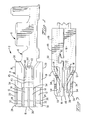
- Figure 1 is a side view of an electrical contact according to the present invention;
- Figure 2 is a front end view of the electrical contact of Figure 1;
- Figure 3 is a top view of the electrical contact of Figure 1;
- Figure 4 is a top sectional view of the electrical contact of Figure 1;
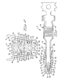
- Figure 5 is a side view of an alternative embodiment of an electrical connector according to the present invention incorporating an outer protective shell thereupon; and,
- Figure 6 is a top sectional view of the electrical contact of Figure 5.
-
- With reference now to Figure 1, an electrical contact according to the present invention is shown generally at 2. The electrical contact 2 includes a
contact portion 4 and aconductor engaging portion 6. In this embodiment, theconductor engaging portion 6 assumes a wire crimp configuration. The conductor engaging portion is connected to the contact portion by way of atransition section 8. -
Contact portion 4 includes abody 10 from which a spaced-apart pair ofouter contact arms 12 and a pair ofinner contact arms 14 extend to atab receiving end 16. Thebody 4 includesside walls corresponding side rails outer contact arms 12. Theextensions contact arms 12 and separated therefrom along the length thereof by anopening 26. The transverse orientation allows theside walls body 4, towards thereceptacle end 16, thecontact arms 12 are joined with theirrespective extensions brackets contact arm 12 and itsrespective side extension - Between each of the
outer contact arms 12 and theinner contact arms 14 is asecond opening 32, whereby theinner contact arms 14 extend outward from thebody 4 towards thereceptacle end 16 free of the adjacentouter contact arm 12. As theinner contact arms 14 are free of theouter contact arms 12, theinner contact arms 14 may move independently thereof to accommodate a misaligned mating tab terminal, thereby assuring the maximum number of contact points possible are established across a tab terminal. Extending along each of thecontact arms 14, adjacent to theopenings 32 and between theinner contact arms 14 and theouter contact arms 12, areupstanding support rails 34 that extend from thebody 10 transversely to the plane of thecontact arms 14. Theserails 34 are configured to cooperate with theinner contact arms 14 in a supporting manner therealong, as described above with respect toside rails transverse support rails 34 are unitarily formed with thecontact arms 14, as is described below. Thesupport rails 34 could however be formed in a manner that has a free end extending over thecontact arms 14 in a supporting manner. Advantageously, in this embodiment, the twoinner contact arms 14 are separated bycentral slot 36 enabling the two inner contact arms to move independently of each other. It may also be desirable to eliminate theslot 36 and provide only a singleinner contact arm 14 supported on both sides bysupport rails 34 between theouter contact arms 12. Additionally, it may be desirable to provide additional contact arms, either supported by transverse rail sections or in an unsupported manner. These possibilities are also within the envisioned scope of the present invention. - Along the
body 10 and opposite thecontact arms contact portion 4 includes arear edge 38 corresponding generally to thetransition portion 8. Thisrear edge 38 is particularly suited for engagement by a secondary locking member of a connector housing (not shown) wherein the contact 2 would be seated. Also disposed along thebody 10 is alocking lance 40 defined by a U-shapedopening 42 and a second opening 43 spaced therefrom and extending across the free ends of the U-shaped opening to form aband 45 therebetween. The U shapedopening 42 has its base generally corresponding to therear edge 38 so that thelocking lance 40 is cantilevered from thebody 10 and folded slightly outward therefrom such that afree end 44 is formed for engaging a shoulder of a mating connector housing. As thelance 40 is cantilevered from theband 45 the resiliency is improved. - With reference now to Figure 2, the electrical connector 2 is shown having complementary configuration shown opposite the aforedescribed to define a
tab receiving region 46 accessible from areceptacle end 16 wherein the mating tab terminal is receivable and engageable by each of thecontact arms - As can be observed in Figure 2, the
outer contact arms 12 extend from spaced apart raisedportions 48 of thebody 10. Theinner contact arms 14 extend from achannel portion 50 located between the raisedportions 48 and recessed relative thereto. Located between the raisedportions 48 and thechannel portion 50 aretransition sections 52. Therails 34 are formed by providing a slit along the edge of thecontact arms 12, along what would correspond to thetransition sections 52 and folding the resultant material between the slit and theinner contact arm 14 perpendicular thereto along to therespective contact arm 14. Thelocking lance 40 is located within thechannel 50. Thebody 10, in the configuration shown in the figures where opposing similar contact structure is provided, assumes a dog-bone cross-sectional shape with the corresponding raisedportions 48 forming the bulbous ends interconnected by a narrower bar-like centre defined by theopposing channel portions 50. - With reference now to Figures 3 and 4, the
support rails 34 are shown free of theinner contact arms 14 along anopening 54 until they are adjoined therewith at atransition section 56. As can be seen in this Figure, oppositely orientatedcontact arms tab receiving region 46 wherein thecontact arms - With reference now to Figures 5 and 6, an alternative embodiment is shown generally at 61. The
contact 61 includes an outerprotective shell 62 about an inner contact 63. The inner contact 63 is configured basically as described above. However, in this embodiment, the alocking lance 64 is carried on theprotective shell 62. The protective shell further overhangs and wraps around the front ends of the contact arms where the tab would be received in a manner well known in the art. - Advantageously then, the present invention provides an electrical contact having at least three contact arms for engaging a tab terminal along a common side where the middle contact arm is provided enhanced stiffness. A contact according to the present invention may be further configured so that the contact arms act independently of each other, thereby assuring that the desired number of contact points are achieved. In addition, the contact is of simple construction and manufacture.
Claims (9)
- An electrical receptacle contact (2) for engaging a complementary tab terminal comprising a contact portion (4) and a conductor engaging portion (6), where the contact portion (4) includes a body (10) and at least three contact arms (12,14,12) including a pair of spaced-apart outer contact arms (12) extending from the body (10) with at least one inner contact arm (14) extending therebetween and the contact arms (12,14,12) have contact surfaces thereupon for engaging a common side of the tab terminal, the receptacle contact (2) being characterized in that the inner contact arm (14) has a transversally disposed support rail (34) extending therealong from the body (10) and operatively cooperating with the inner contact arm (14) to provide enhanced stiffness.
- The receptacle contact (2) of claim 1, further characterized in that the contact arms (12,14,12) are independent of each other.
- The receptacle contact (2) of claim 1, further characterized in that the body (10) from which the contact arms (12, 14) extend has a pair of spaced apart raised portions (48) from which the outer contact arms (12) extend and a channel (50) therebetween from which the inner contact arm (14) extends.
- The receptacle contact (2) of claim 3, further characterized in that the body (10) includes a transition portion (52) between the raised portion (48) and the channel (50), where the transition portion (52) is formed into the support rail (34).
- The receptacle contact (2) of claim 1, further characterized in that the receptacle contact (2) includes a second set of equally configured contact arms (12,14,12) disposed oppositely from the first set to form a tab receiving region (46) therebetween.
- The receptacle contact of any one of the preceding claims, further characterized in that a second inner contact (14) is located along the first inner contact (14) and one of the outer contacts (12).
- The receptacle contact of claim 6, further characterized in that the second inner contact (14) is also supported by a corresponding transverse support rail (34), the transverse support rail (34) being positioned along the inner contact arm (14) adjacent the adjacent outer contact arm (12).
- The receptacle contact of any one of claims 1-7, further characterized in that the outer contact arms (12) are supported by transverse rails (22,24).
- The receptacle contact of any one of the preceding claims, further characterized in that the receptacle contact (2) is of one piece construction.
Applications Claiming Priority (2)
| Application Number | Priority Date | Filing Date | Title |
|---|---|---|---|
| GBGB9507187.4A GB9507187D0 (en) | 1995-04-06 | 1995-04-06 | Contact having an independently supported inner contact arm |
| GB9507187 | 1995-04-06 |
Publications (2)
| Publication Number | Publication Date |
|---|---|
| EP0736930A1 EP0736930A1 (en) | 1996-10-09 |
| EP0736930B1 true EP0736930B1 (en) | 2000-07-12 |
Family
ID=10772672
Family Applications (1)
| Application Number | Title | Priority Date | Filing Date |
|---|---|---|---|
| EP96105429A Expired - Lifetime EP0736930B1 (en) | 1995-04-06 | 1996-04-04 | Contact having an independently supported inner contact arm |
Country Status (5)
| Country | Link |
|---|---|
| US (1) | US5795196A (en) |
| EP (1) | EP0736930B1 (en) |
| JP (1) | JPH08315888A (en) |
| DE (1) | DE69609230T2 (en) |
| GB (1) | GB9507187D0 (en) |
Families Citing this family (6)
| Publication number | Priority date | Publication date | Assignee | Title |
|---|---|---|---|---|
| US5938485A (en) * | 1996-09-30 | 1999-08-17 | The Whitaker Corporation | Electrical terminal |
| DE10351540B3 (en) * | 2003-11-03 | 2005-08-11 | Intedis Gmbh & Co. Kg | Flat plug socket |
| US7722362B2 (en) * | 2006-06-22 | 2010-05-25 | Watlow Electric Manufacturing Company | Sensor adaptor circuit housing incapsulating connection of an input connector with a wire |
| US7665890B2 (en) | 2006-06-22 | 2010-02-23 | Watlow Electric Manufacturing Company | Temperature sensor assembly and method of manufacturing thereof |
| EP2642598B1 (en) | 2012-03-19 | 2017-09-13 | Yazaki Europe Ltd | Electric terminal |
| US10826215B2 (en) * | 2018-09-25 | 2020-11-03 | Alltop Electronics (Suzhou) Ltd. | Electrical connector and electrical connector assembly with the same |
Family Cites Families (11)
| Publication number | Priority date | Publication date | Assignee | Title |
|---|---|---|---|---|
| GB1171678A (en) * | 1967-06-06 | 1969-11-26 | Amp Inc | Electrical connector tab receptacle |
| ZA712691B (en) * | 1970-05-22 | 1972-01-26 | Amp Inc | Contact element for a printed circuit edge connector |
| US4351583A (en) * | 1980-06-19 | 1982-09-28 | Gte Products Corporation | Electrical terminal |
| DE3248078C2 (en) * | 1982-12-24 | 1986-03-27 | Grote & Hartmann Gmbh & Co Kg, 5600 Wuppertal | Double flat spring contact with overspring |
| DE3424072A1 (en) * | 1984-06-29 | 1986-01-09 | Grote & Hartmann | Plug connector |
| US4772234A (en) * | 1987-07-29 | 1988-09-20 | Amp Incorporated | Terminal for establishing electrical contact with a post |
| GB8728575D0 (en) * | 1987-12-07 | 1988-01-13 | Amp Gmbh | Electrical socket terminal |
| US4907990A (en) * | 1988-10-07 | 1990-03-13 | Molex Incorporated | Elastically supported dual cantilever beam pin-receiving electrical contact |
| US4865567A (en) * | 1988-10-11 | 1989-09-12 | Intercon Systems, Inc. | Miniature barrel female terminal |
| FR2649251B1 (en) * | 1989-07-03 | 1992-09-04 | Labinal | FEMALE ELECTRIC CONTACT MEMBER |
| US5417589A (en) * | 1993-01-21 | 1995-05-23 | Sumitomo Wiring Systems, Ltd | Linked electrical connectors |
-
1995
- 1995-04-06 GB GBGB9507187.4A patent/GB9507187D0/en active Pending
-
1996
- 1996-03-28 US US08/623,581 patent/US5795196A/en not_active Expired - Fee Related
- 1996-04-04 DE DE69609230T patent/DE69609230T2/en not_active Expired - Fee Related
- 1996-04-04 EP EP96105429A patent/EP0736930B1/en not_active Expired - Lifetime
- 1996-04-05 JP JP8171683A patent/JPH08315888A/en active Pending
Also Published As
| Publication number | Publication date |
|---|---|
| US5795196A (en) | 1998-08-18 |
| DE69609230T2 (en) | 2001-01-04 |
| GB9507187D0 (en) | 1995-05-31 |
| DE69609230D1 (en) | 2000-08-17 |
| JPH08315888A (en) | 1996-11-29 |
| EP0736930A1 (en) | 1996-10-09 |
Similar Documents
| Publication | Publication Date | Title |
|---|---|---|
| EP0932917B1 (en) | Electrical connector having a housing and an electrical contact | |
| EP0600419B1 (en) | Electrical socket terminal | |
| EP0678936B1 (en) | Miniature anti-fretting receptacle terminal | |
| EP0848454B1 (en) | Electrical contact | |
| US5582519A (en) | Make-first-break-last ground connections | |
| EP0688065B1 (en) | Electrical receptacle terminal | |
| US6077131A (en) | Male terminal | |
| US5938485A (en) | Electrical terminal | |
| EP0935827B1 (en) | Contact with latch for contact retention and housing therefor | |
| EP0697752A2 (en) | Electrical receptacle terminal | |
| EP0795930B1 (en) | High contact force pin-receiving electrical contact | |
| EP0759213B1 (en) | Universal contact receptacle | |
| US5980297A (en) | Lock arm deformation prevention construction | |
| EP0687033B1 (en) | High current receptacle terminal | |
| JP2631258B2 (en) | Male electrical terminal having excessive stress prevention means | |
| EP0178102A2 (en) | Electrical terminals and connector assemblies | |
| US5611716A (en) | Electrical contact having improved secondary locking surfaces | |
| US5795196A (en) | Contact having an independently supported inner contact arm | |
| EP0700122B1 (en) | Electrical receptacle terminal | |
| KR20010014213A (en) | Flat plug contact organ for electrical connectors | |
| KR100540827B1 (en) | Short Circuit Terminals and Connectors | |
| EP1089387A2 (en) | A modular female electrical terminal | |
| EP0570039B1 (en) | Electrical terminal | |
| EP0979543B1 (en) | Electrical contact | |
| US5122083A (en) | Resilient terminal with buckling prevention mechanism |
Legal Events
| Date | Code | Title | Description |
|---|---|---|---|
| PUAI | Public reference made under article 153(3) epc to a published international application that has entered the european phase |
Free format text: ORIGINAL CODE: 0009012 |
|
| AK | Designated contracting states |
Kind code of ref document: A1 Designated state(s): DE FR GB IT |
|
| 17P | Request for examination filed |
Effective date: 19961203 |
|
| 17Q | First examination report despatched |
Effective date: 19990422 |
|
| GRAG | Despatch of communication of intention to grant |
Free format text: ORIGINAL CODE: EPIDOS AGRA |
|
| GRAG | Despatch of communication of intention to grant |
Free format text: ORIGINAL CODE: EPIDOS AGRA |
|
| GRAH | Despatch of communication of intention to grant a patent |
Free format text: ORIGINAL CODE: EPIDOS IGRA |
|
| GRAH | Despatch of communication of intention to grant a patent |
Free format text: ORIGINAL CODE: EPIDOS IGRA |
|
| GRAA | (expected) grant |
Free format text: ORIGINAL CODE: 0009210 |
|
| AK | Designated contracting states |
Kind code of ref document: B1 Designated state(s): DE FR GB IT |
|
| PG25 | Lapsed in a contracting state [announced via postgrant information from national office to epo] |
Ref country code: IT Free format text: LAPSE BECAUSE OF FAILURE TO SUBMIT A TRANSLATION OF THE DESCRIPTION OR TO PAY THE FEE WITHIN THE PRE;WARNING: LAPSES OF ITALIAN PATENTS WITH EFFECTIVE DATE BEFORE 2007 MAY HAVE OCCURRED AT ANY TIME BEFORE 2007. THE CORRECT EFFECTIVE DATE MAY BE DIFFERENT FROM THE ONE RECORDED.SCRIBED TIME-LIMIT Effective date: 20000712 Ref country code: FR Free format text: THE PATENT HAS BEEN ANNULLED BY A DECISION OF A NATIONAL AUTHORITY Effective date: 20000712 |
|
| REF | Corresponds to: |
Ref document number: 69609230 Country of ref document: DE Date of ref document: 20000817 |
|
| ET | Fr: translation filed | ||
| PG25 | Lapsed in a contracting state [announced via postgrant information from national office to epo] |
Ref country code: GB Free format text: LAPSE BECAUSE OF NON-PAYMENT OF DUE FEES Effective date: 20010404 |
|
| PLBE | No opposition filed within time limit |
Free format text: ORIGINAL CODE: 0009261 |
|
| STAA | Information on the status of an ep patent application or granted ep patent |
Free format text: STATUS: NO OPPOSITION FILED WITHIN TIME LIMIT |
|
| 26N | No opposition filed | ||
| GBPC | Gb: european patent ceased through non-payment of renewal fee |
Effective date: 20010404 |
|
| REG | Reference to a national code |
Ref country code: FR Ref legal event code: ST |
|
| PGFP | Annual fee paid to national office [announced via postgrant information from national office to epo] |
Ref country code: DE Payment date: 20090429 Year of fee payment: 14 |
|
| PG25 | Lapsed in a contracting state [announced via postgrant information from national office to epo] |
Ref country code: DE Free format text: LAPSE BECAUSE OF NON-PAYMENT OF DUE FEES Effective date: 20101103 |