EP0735960B1 - Rotatable seat belt buckle mounting bracket for a wehicle seat adjuster with a catcher bracket buckle brace - Google Patents
Rotatable seat belt buckle mounting bracket for a wehicle seat adjuster with a catcher bracket buckle brace Download PDFInfo
- Publication number
- EP0735960B1 EP0735960B1 EP95909207A EP95909207A EP0735960B1 EP 0735960 B1 EP0735960 B1 EP 0735960B1 EP 95909207 A EP95909207 A EP 95909207A EP 95909207 A EP95909207 A EP 95909207A EP 0735960 B1 EP0735960 B1 EP 0735960B1
- Authority
- EP
- European Patent Office
- Prior art keywords
- track
- upper track
- seat belt
- belt buckle
- seat
- Prior art date
- Legal status (The legal status is an assumption and is not a legal conclusion. Google has not performed a legal analysis and makes no representation as to the accuracy of the status listed.)
- Expired - Lifetime
Links
- 230000000712 assembly Effects 0.000 claims description 11
- 238000000429 assembly Methods 0.000 claims description 11
- 239000004033 plastic Substances 0.000 claims description 7
- 229920003023 plastic Polymers 0.000 claims description 7
- 239000000463 material Substances 0.000 claims description 6
- 230000008878 coupling Effects 0.000 claims description 2
- 238000010168 coupling process Methods 0.000 claims description 2
- 238000005859 coupling reaction Methods 0.000 claims description 2
- 238000010276 construction Methods 0.000 description 3
- 230000007246 mechanism Effects 0.000 description 3
- 229910001209 Low-carbon steel Inorganic materials 0.000 description 2
- 230000008901 benefit Effects 0.000 description 2
- 230000008859 change Effects 0.000 description 2
- 238000009434 installation Methods 0.000 description 2
- 238000012986 modification Methods 0.000 description 2
- 230000004048 modification Effects 0.000 description 2
- 230000036961 partial effect Effects 0.000 description 2
- 230000003068 static effect Effects 0.000 description 2
- 238000003466 welding Methods 0.000 description 2
- 229910000851 Alloy steel Inorganic materials 0.000 description 1
- 229910000831 Steel Inorganic materials 0.000 description 1
- 208000027418 Wounds and injury Diseases 0.000 description 1
- 230000002411 adverse Effects 0.000 description 1
- 230000015572 biosynthetic process Effects 0.000 description 1
- 150000001875 compounds Chemical class 0.000 description 1
- 230000006378 damage Effects 0.000 description 1
- 230000009977 dual effect Effects 0.000 description 1
- 238000001125 extrusion Methods 0.000 description 1
- 208000014674 injury Diseases 0.000 description 1
- 230000014759 maintenance of location Effects 0.000 description 1
- 238000004519 manufacturing process Methods 0.000 description 1
- 239000002184 metal Substances 0.000 description 1
- 238000000034 method Methods 0.000 description 1
- 229920002635 polyurethane Polymers 0.000 description 1
- 239000004814 polyurethane Substances 0.000 description 1
- 230000008569 process Effects 0.000 description 1
- 230000001681 protective effect Effects 0.000 description 1
- 230000000717 retained effect Effects 0.000 description 1
- 238000000926 separation method Methods 0.000 description 1
- 239000010959 steel Substances 0.000 description 1
- 239000003351 stiffener Substances 0.000 description 1
- 238000005728 strengthening Methods 0.000 description 1
Images


Classifications
-
- B—PERFORMING OPERATIONS; TRANSPORTING
- B60—VEHICLES IN GENERAL
- B60R—VEHICLES, VEHICLE FITTINGS, OR VEHICLE PARTS, NOT OTHERWISE PROVIDED FOR
- B60R22/00—Safety belts or body harnesses in vehicles
- B60R22/18—Anchoring devices
- B60R22/26—Anchoring devices secured to the seat
-
- B—PERFORMING OPERATIONS; TRANSPORTING
- B60—VEHICLES IN GENERAL
- B60N—SEATS SPECIALLY ADAPTED FOR VEHICLES; VEHICLE PASSENGER ACCOMMODATION NOT OTHERWISE PROVIDED FOR
- B60N2/00—Seats specially adapted for vehicles; Arrangement or mounting of seats in vehicles
- B60N2/02—Seats specially adapted for vehicles; Arrangement or mounting of seats in vehicles the seat or part thereof being movable, e.g. adjustable
- B60N2/0224—Non-manual adjustments, e.g. with electrical operation
- B60N2/02246—Electric motors therefor
-
- B—PERFORMING OPERATIONS; TRANSPORTING
- B60—VEHICLES IN GENERAL
- B60N—SEATS SPECIALLY ADAPTED FOR VEHICLES; VEHICLE PASSENGER ACCOMMODATION NOT OTHERWISE PROVIDED FOR
- B60N2/00—Seats specially adapted for vehicles; Arrangement or mounting of seats in vehicles
- B60N2/02—Seats specially adapted for vehicles; Arrangement or mounting of seats in vehicles the seat or part thereof being movable, e.g. adjustable
- B60N2/04—Seats specially adapted for vehicles; Arrangement or mounting of seats in vehicles the seat or part thereof being movable, e.g. adjustable the whole seat being movable
- B60N2/06—Seats specially adapted for vehicles; Arrangement or mounting of seats in vehicles the seat or part thereof being movable, e.g. adjustable the whole seat being movable slidable
- B60N2/067—Seats specially adapted for vehicles; Arrangement or mounting of seats in vehicles the seat or part thereof being movable, e.g. adjustable the whole seat being movable slidable by linear actuators, e.g. linear screw mechanisms
-
- B—PERFORMING OPERATIONS; TRANSPORTING
- B60—VEHICLES IN GENERAL
- B60N—SEATS SPECIALLY ADAPTED FOR VEHICLES; VEHICLE PASSENGER ACCOMMODATION NOT OTHERWISE PROVIDED FOR
- B60N2/00—Seats specially adapted for vehicles; Arrangement or mounting of seats in vehicles
- B60N2/02—Seats specially adapted for vehicles; Arrangement or mounting of seats in vehicles the seat or part thereof being movable, e.g. adjustable
- B60N2/04—Seats specially adapted for vehicles; Arrangement or mounting of seats in vehicles the seat or part thereof being movable, e.g. adjustable the whole seat being movable
- B60N2/06—Seats specially adapted for vehicles; Arrangement or mounting of seats in vehicles the seat or part thereof being movable, e.g. adjustable the whole seat being movable slidable
- B60N2/07—Slide construction
- B60N2/0702—Slide construction characterised by its cross-section
- B60N2/0705—Slide construction characterised by its cross-section omega-shaped
-
- B—PERFORMING OPERATIONS; TRANSPORTING
- B60—VEHICLES IN GENERAL
- B60N—SEATS SPECIALLY ADAPTED FOR VEHICLES; VEHICLE PASSENGER ACCOMMODATION NOT OTHERWISE PROVIDED FOR
- B60N2/00—Seats specially adapted for vehicles; Arrangement or mounting of seats in vehicles
- B60N2/02—Seats specially adapted for vehicles; Arrangement or mounting of seats in vehicles the seat or part thereof being movable, e.g. adjustable
- B60N2/04—Seats specially adapted for vehicles; Arrangement or mounting of seats in vehicles the seat or part thereof being movable, e.g. adjustable the whole seat being movable
- B60N2/06—Seats specially adapted for vehicles; Arrangement or mounting of seats in vehicles the seat or part thereof being movable, e.g. adjustable the whole seat being movable slidable
- B60N2/07—Slide construction
- B60N2/0702—Slide construction characterised by its cross-section
- B60N2/0715—C or U-shaped
-
- B—PERFORMING OPERATIONS; TRANSPORTING
- B60—VEHICLES IN GENERAL
- B60N—SEATS SPECIALLY ADAPTED FOR VEHICLES; VEHICLE PASSENGER ACCOMMODATION NOT OTHERWISE PROVIDED FOR
- B60N2/00—Seats specially adapted for vehicles; Arrangement or mounting of seats in vehicles
- B60N2/02—Seats specially adapted for vehicles; Arrangement or mounting of seats in vehicles the seat or part thereof being movable, e.g. adjustable
- B60N2/04—Seats specially adapted for vehicles; Arrangement or mounting of seats in vehicles the seat or part thereof being movable, e.g. adjustable the whole seat being movable
- B60N2/06—Seats specially adapted for vehicles; Arrangement or mounting of seats in vehicles the seat or part thereof being movable, e.g. adjustable the whole seat being movable slidable
- B60N2/07—Slide construction
- B60N2/075—Slide construction roller-less
-
- B—PERFORMING OPERATIONS; TRANSPORTING
- B60—VEHICLES IN GENERAL
- B60N—SEATS SPECIALLY ADAPTED FOR VEHICLES; VEHICLE PASSENGER ACCOMMODATION NOT OTHERWISE PROVIDED FOR
- B60N2/00—Seats specially adapted for vehicles; Arrangement or mounting of seats in vehicles
- B60N2/02—Seats specially adapted for vehicles; Arrangement or mounting of seats in vehicles the seat or part thereof being movable, e.g. adjustable
- B60N2/04—Seats specially adapted for vehicles; Arrangement or mounting of seats in vehicles the seat or part thereof being movable, e.g. adjustable the whole seat being movable
- B60N2/16—Seats specially adapted for vehicles; Arrangement or mounting of seats in vehicles the seat or part thereof being movable, e.g. adjustable the whole seat being movable height-adjustable
- B60N2/18—Seats specially adapted for vehicles; Arrangement or mounting of seats in vehicles the seat or part thereof being movable, e.g. adjustable the whole seat being movable height-adjustable the front or the rear portion of the seat being adjustable, e.g. independently of each other
- B60N2/1803—Seats specially adapted for vehicles; Arrangement or mounting of seats in vehicles the seat or part thereof being movable, e.g. adjustable the whole seat being movable height-adjustable the front or the rear portion of the seat being adjustable, e.g. independently of each other with independent front and/or rear adjustment
-
- B—PERFORMING OPERATIONS; TRANSPORTING
- B60—VEHICLES IN GENERAL
- B60N—SEATS SPECIALLY ADAPTED FOR VEHICLES; VEHICLE PASSENGER ACCOMMODATION NOT OTHERWISE PROVIDED FOR
- B60N2/00—Seats specially adapted for vehicles; Arrangement or mounting of seats in vehicles
- B60N2/02—Seats specially adapted for vehicles; Arrangement or mounting of seats in vehicles the seat or part thereof being movable, e.g. adjustable
- B60N2/22—Seats specially adapted for vehicles; Arrangement or mounting of seats in vehicles the seat or part thereof being movable, e.g. adjustable the back-rest being adjustable
- B60N2/23—Seats specially adapted for vehicles; Arrangement or mounting of seats in vehicles the seat or part thereof being movable, e.g. adjustable the back-rest being adjustable by linear actuators, e.g. linear screw mechanisms
- B60N2/233—Seats specially adapted for vehicles; Arrangement or mounting of seats in vehicles the seat or part thereof being movable, e.g. adjustable the back-rest being adjustable by linear actuators, e.g. linear screw mechanisms by linear screw mechanisms
-
- B—PERFORMING OPERATIONS; TRANSPORTING
- B60—VEHICLES IN GENERAL
- B60N—SEATS SPECIALLY ADAPTED FOR VEHICLES; VEHICLE PASSENGER ACCOMMODATION NOT OTHERWISE PROVIDED FOR
- B60N2/00—Seats specially adapted for vehicles; Arrangement or mounting of seats in vehicles
- B60N2/24—Seats specially adapted for vehicles; Arrangement or mounting of seats in vehicles for particular purposes or particular vehicles
- B60N2/42—Seats specially adapted for vehicles; Arrangement or mounting of seats in vehicles for particular purposes or particular vehicles the seat constructed to protect the occupant from the effect of abnormal g-forces, e.g. crash or safety seats
- B60N2/4207—Seats specially adapted for vehicles; Arrangement or mounting of seats in vehicles for particular purposes or particular vehicles the seat constructed to protect the occupant from the effect of abnormal g-forces, e.g. crash or safety seats characterised by the direction of the g-forces
- B60N2/4214—Seats specially adapted for vehicles; Arrangement or mounting of seats in vehicles for particular purposes or particular vehicles the seat constructed to protect the occupant from the effect of abnormal g-forces, e.g. crash or safety seats characterised by the direction of the g-forces longitudinal
- B60N2/4221—Seats specially adapted for vehicles; Arrangement or mounting of seats in vehicles for particular purposes or particular vehicles the seat constructed to protect the occupant from the effect of abnormal g-forces, e.g. crash or safety seats characterised by the direction of the g-forces longitudinal due to impact coming from the front
-
- B—PERFORMING OPERATIONS; TRANSPORTING
- B60—VEHICLES IN GENERAL
- B60N—SEATS SPECIALLY ADAPTED FOR VEHICLES; VEHICLE PASSENGER ACCOMMODATION NOT OTHERWISE PROVIDED FOR
- B60N2/00—Seats specially adapted for vehicles; Arrangement or mounting of seats in vehicles
- B60N2/24—Seats specially adapted for vehicles; Arrangement or mounting of seats in vehicles for particular purposes or particular vehicles
- B60N2/42—Seats specially adapted for vehicles; Arrangement or mounting of seats in vehicles for particular purposes or particular vehicles the seat constructed to protect the occupant from the effect of abnormal g-forces, e.g. crash or safety seats
- B60N2/427—Seats or parts thereof displaced during a crash
- B60N2/42709—Seats or parts thereof displaced during a crash involving residual deformation or fracture of the structure
-
- B—PERFORMING OPERATIONS; TRANSPORTING
- B60—VEHICLES IN GENERAL
- B60N—SEATS SPECIALLY ADAPTED FOR VEHICLES; VEHICLE PASSENGER ACCOMMODATION NOT OTHERWISE PROVIDED FOR
- B60N2/00—Seats specially adapted for vehicles; Arrangement or mounting of seats in vehicles
- B60N2/68—Seat frames
Definitions
- the present invention relates, in general, to vehicle seats, and, more specifically, to seat belt attachments to vehicle seat adjusters.
- Seat adjusters are used on the front seat(s) of automotive vehicles to provide selective horizontal fore and aft, vertical and/or recliner movements of the seat.
- Such seat adjusters carry an upper support frame which supports the seat bottom and sometimes the seat back of the vehicle seat.
- the upper support frame is mounted on first and second, spaced track assemblies, each formed of an upper track which is connected to the upper support frame and which is slidably mounted in a lower track anchored to the vehicle floor.
- a drive mechanism typically formed of a bi-directional electric motor, is mounted between the track assemblies and rotates a pair of drive shafts extending outward from the motor to a gear assembly or box mounted on each upper track.
- the gear box rotates a lead screw extending below each upper track.
- a drive block mounted to the lower track threadingly receives the lead screw to cause reciprocal movement of the upper track and the attached upper support frame upon selective energization of the drive motor.
- Other drive mechanisms may also be incorporated into the power seat adjuster to provide vertical movement of the seat frame as well as pivotal movement of the seat back with respect to the seat bottom.
- the seat adjuster provide easy fore and aft movement of the seat in the lower tracks, it is imperative that the seat remain in a fixed, stationary position during a collision, such as a frontal collision, in order to prevent injury to the passenger using the seat.
- the weight and size of the seat adjuster components are selected to provide a maximum amount of strength to resist any movement under the high impact forces transmitted to the seat through the seat belt during a vehicle collision.
- the individual tracks, the torsion tubes or bars typically extending between and interconnecting the spaced upper tracks into a rigid structure and the other components of the seat adjuster are made with stronger materials and greater thicknesses and dimensions to provide the requisite amount of strength.
- a fixed seat belt buckle mounting bracket is mounted on the rear end of one of the movable upper tracks.
- the seat belt buckle mounting brackets typically have an L-shape and are fixedly attached to the upper track by welding or by fasteners.
- One leg of the bracket is attached directly to the upper track, while the second leg extends integrally from the first leg upward from the upper track.
- This arrangement provides a stiffener for the upper track as well as providing a retention device for attaching a fixed seat belt carrying a bracket which receives the tongue of a corresponding seat belt portion extendably and retractably mounted on a reel.
- an upper track for a vehicle seat adjuster which has an improved seat belt buckle attachment means which overcomes the problems of previously devised seat belt buckle attachment means. It would also be desirable to provide an upper track of a seat adjuster having a seat belt buckle mounting bracket which is designed to change its geometry and/or position under load from a weak geometry position to a stronger geometry position. Furthermore, it would be desirable to provide a means for transferring load from the seat belt buckle attachment mounting bracket and upper track to the torsion bar assembly of the seat. It would also be desirable to gain higher loads during static loading, and greater reliability in the buckle system. In addition, it would be desirable to improve manufacturability by eliminating welds and reducing installation processing.
- the present invention is a track assembly for a vehicle seat adjuster which has an improved seat belt buckle attachment means whose geometry changes under load to a strong, high strength geometry position to prevent fracture or breakage of the seat belt buckle attachment means and also transfers the load from the seat belt buckle attachment assembly and upper track to the torsion bar assembly.
- the track assembly includes a stationary lower track which is adapted to be anchored to the floor pan of a vehicle.
- An upper track is adapted to support a vehicle seat and is movably mounted on the lower track.
- Means are provided for adjusting the upper track relative to the lower track for fore and aft movement of the upper track in the lower track.
- Seat belt buckle attachment means are mounted on the upper track for attaching a fixed seat belt buckle to the upper track.
- the seat belt buckle attachment means includes a member having first and second angularly disposed legs.
- the second leg is adapted to be attached to a fixed seat belt buckle.
- Means are provided for fixedly attaching the first leg to the upper track in a first, normal operating position and for allowing rotation of the member to a second position relative to the upper track under a predetermined force imposed on the member through the seat belt buckle attached thereto to place the first and second legs of the member in tension.
- the seat belt buckle attachment means is an integral, one-piece member with the first and second legs being disposed at an obtuse angle with respect to each other.
- the second leg In the first, normal operating position, the second leg extends upward from the upper track and is disposed adjacent to a side wall of the upper track.
- the second leg In the second position, the second leg is disposed substantially co-axial with the longitudinal axis of the upper track to place the first and second legs of the member in tension which presents a stronger geometry position for the seat belt buckle mounting bracket and which has a higher strength to resist fracture, deformation, etc.
- a catcher bracket buckle brace means is provided to connect the seat belt buckle attachment means and upper track to the torsion bar or tube assembly.
- the catcher bracket buckle brace means preferably includes an elongated strap connected to the seat belt buckle attachment means and upper track at both ends and wrapped around the rear torsion bar intermediate the ends of the strap. During a frontal collision, the strap transfers load from the seat belt buckle attachment means and the upper track to the rear torsion bar assembly, thereby increasing the amount of load carried through the structure before failure.
- the seat belt buckle mounting bracket employed in a track assembly for a vehicle seat adjuster overcomes problems associated with previously devised seat belt buckle mounting brackets that are attached in a fixed and stationary manner to the movable upper track of a vehicle seat adjuster.
- the seat belt buckle mounting bracket can rotate under a load imposed on the seat belt buckle mounting bracket through the seat belt to a stronger geometry position which resists fracture or breakage and which insures that the seat belt buckle mounting bracket remains attached to the upper track of the track assembly during a frontal vehicle collision and despite any deformation or upward movement of the upper track with respect to the stationary and fixed lower track.
- the catcher bracket buckle brace means transfers the load effectively from the seat belt buckle mounting bracket and upper track to the rear torsion bar assembly for increased load capabilities during frontal vehicle collisions.
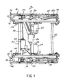
- a seat adjuster 10 which variably positions an automotive vehicle seat in any user selected position.
- the seat adjuster 10 depicted is a power seat adjuster, and is a so-called "eight-way" adjuster providing horizontal fore/aft, vertical up and down movement of separate front and rear portions of the adjuster as well as pivotal tilting of the seat back with respect to the seat bottom.
- the present invention described hereafter is employable with either a manual or a power seat adjuster which includes at least a horizontal fore/aft movement and any number of other movements.
- the catcher bracket buckle brace of the present invention can be employed on the inboard upper track assembly of either the driver's side, or the passenger's side, vehicle seat.
- the seat adjuster 10 supports a conventional vehicle seat, not shown, which includes a seat bottom and a seat back.
- An upper support frame is provided on the seat adjuster 10 for supporting and connecting the seat bottom and seat back to the seat adjuster 10.
- the upper support frame includes a pair of spaced, longitudinally extending frame members or rails 12 and 14.
- Mounting brackets 16 and 18, for example, are mounted on the ends of the frame members 12 and 14, respectively, and provide a mounting surface for connecting the seat bottom to the upper support frame.
- a pair of hinge plates 20 are also mounted on the upper support frame and provide a pivot connection between the seat back and seat bottom to permit selective tilting or pivotal movement of the seat back with respect to the seat bottom as is typical in so-called "seat recliners".
- Various drive assemblies are depicted mounted on the seat adjuster 10 to provide selective movement of the seat adjuster 10 along various axes.
- front and rear vertical drive motors 22 and 24, respectively are mounted on the seat adjuster 10 and connected to conventional lead screws and drive blocks or nuts to move front and rear portions of the vehicle seat to provide selective vertical adjustment of the front and rear portions of the vehicle seat.
- a recliner drive motor 26 is interconnected by a pair of rotatable drive shafts 28 to gear boxes 30 which are each coupled to a lead screw 32.
- the lead screws 32 are connected to one of the pivotal seat back hinge plates 20 mounted on opposite sides of the seat adjuster 10 to provide selective pivotal adjustment of the seat back with respect to the seat bottom.
- a horizontal drive means formed of a bi-directional electric motor 34 which is fixedly mounted to one of the upper tracks 52 by means of a suitable bracket 38.
- a pair of rotatable output shafts 40 extend outward from the horizontal drive motor 34 to a rotatable connection with a lead screw by a gear means mounted in opposed track assemblies as described hereafter.
- the output shafts 40 are, in an exemplary embodiment, flexible steel shafts covered by a polyurethane sleeve.
- the seat adjuster 10 also includes a rear torsion bar or member 42 and a front torsion bar or member 44.
- This pair of tubular torsion bars or members 42 and 44 extend between and are connected to the opposed track assemblies 46 and 48 and provide a rigid support structure for the seat adjuster 10.
- the following description will refer to only one track assembly 48. It will be understood that the opposite track assembly 46 is constructed in the same manner.
- the track assembly 48 includes a lower track 50 and an upper track 52 which is slidably disposed within the lower track 50 and reciprocally movable bi-directionally along the lower track 50 under the control of the horizontal drive means 34.
- the lower track 50 is formed of an integral, one-piece member having a substantially planar central wall or web 54 and a pair of identically formed side walls 56 and 58 extending from opposite sides of the central wall 54.
- Each of the side walls 56 and 58 includes a vertically extending, outer side wall 60, a top wall 62 and an inward disposed lip or wall 64 which extends substantially vertically downward from the top wall 62 and is spaced from the outer side wall 60.
- the outer side wall 60, the top wall 62 and the inner wall 64 are formed in an inverted J-shape creating and surrounding a longitudinal extending channel 72.
- the lower edge of the inner wall 64 is spaced from the central wall 54 of the lower track 50 to define a longitudinally extending slot therebetween as denoted by reference number 66.
- a plurality of spaced apertures 68 are formed in the outer side walls 60 of each side wall 56 and 58.
- a slide member or sleeve 70 is mounted in each channel 72 formed by the spaced portions of the central wall 54, the outer side wall 60, the top wall 62 and the inner wall 64 on opposite sides of the lower track 50.
- the slide or sleeve 70 is substantially C-shaped and is complimentary to the shape of the channel 72.
- the sleeve 70 is formed of a suitable plastic material to provide a smooth sliding surface for the upper track 52, described hereafter, which is slidingly disposed within the slide or sleeve 70.
- a plurality of outwardly extending pins 74 are formed on and extend outward from a side wall of the slide or sleeve 70 and engage the apertures 68 in the outer side wall 60 of the corresponding side walls 56 and 58 of the lower track 50 to securely and position the slide or sleeve 70 in a stationary manner within the lower track 50.
- a front riser 80 and a rear riser 82 are attached to the lower track 50 at opposite ends thereof and provide a mounting connection to the vehicle floor by means of bolts or other suitable fasteners or anchors.
- the upper track 52 is in the form of an elongated, one-piece, integrally formed member which is stamped, extruded, or otherwise formed from a suitable material, such as a high-strength, low alloy steel.
- the upper track 52 includes a first end 84 and an opposed second end 86.
- a raised central portion or surface 88 extends between the first and second ends 84 and 86.
- the side walls of the upper track 52 are formed in a channel-like configuration complimentary to the shape of the channels 72 in the lower track 50 so as to enable the upper track 52 to be slidably disposed within the lower track 50 in sliding contact with the sleeves 70.
- each side wall of the upper track 52 is formed with a substantially J-shaped channel configuration formed of an outer side wall 90, a lower bottom wall 92 and an inner side wall 94 which extends to the central raised portion 88.
- the same channel-like configuration is also provided for the opposite longitudinal side wall of the upper track 52.
- a pair of overlapping flanges 96 and 98 are formed at the second end 86 of the upper track 52.
- Aligned apertures 100 are formed in each of the flanges 96 and 98 and provide a mounting point for the attachment of a seat belt buckle bracket 102 to the second end 86 of the upper track 52.
- the seat belt buckle bracket 102 provides an attachment point for a conventional seat belt buckle, not shown.
- a first pair 104 of mounting flanges including spaced mounting flanges 106 and 108 are integrally formed in the upper track 52 adjacent the first end 84 thereof.
- a second pair 110 of mounting flanges including first and second mounting flanges 112 and 114 are integrally formed in the upper track 52 adjacent the overlapped flanges 96 and 98 at the second end 86 of the upper track 52.
- Each of the pairs 104 and 110 of mounting flanges is cut, such as by stamping, from the same material sheet used to form the entire one-piece upper track 52.
- each pair of flanges 104 and 110 are then bent outwardly from the raised central portion 88 of the upper track 52 so as to be disposed in a substantially vertically extending position when the upper track 52 is mounted in its operating position in the seat adjuster 10.
- Each of the mounting flanges 106, 108, 112 and 114 forming the first and second pair of mounting flanges 104 and 110 is substantially identically constructed with the exception of the mounting flange 106 which has an elongated end portion 116.
- An enlarged aperture 118 is formed in the end portion 116 to enable the drive shaft 40 of the horizontal drive motor 34 to pass therethrough to its connection to the horizontal gear means, as described hereafter.
- a pair of co-axial aligned apertures 120 are formed in the mounting flanges 106 and 108 of the first pair of mounting flanges 104.
- the apertures 120 are preferably formed by an extrusion process which creates an inwardly extending, annular collar 122 extending toward the opposed mounting flange 106 or 108.
- the aligned apertures 120 provide a mounting connection for the front tubular torsion bar 44 to the upper track 52 as described hereafter.
- Similar coaxial apertures 124 are formed in the mounting flanges 112 and 114 of the second pair of mounting flanges 110 and are each formed with inwardly facing annular collars 126.
- the mounting apertures 124 provide a mounting connection for the other tubular torsion tube 42 as described hereafter.
- a plurality of longitudinally spaced apertures each having an outwardly extending, annular collar 128 are formed on the raised central portion 88 of the upper track 52 and provide a mounting connection for a bracket used to attach the vertical drive motors 22 or 24 to each upper track 52.
- each torsion bar or tube such as rear torsion tube 42, extends through the aligned apertures in the mounting flanges 112 and 114 and the annular collars 126 associated therewith to connect the torsion tube 42 to the upper track 52.
- a fastener 130 such as a conventional push nut, is mounted on the outer end of the torsion tube 42 to securely attach the torsion tube 42 to the mounting flange 114.
- each torsion tube, such as front torsion tube 44 is welded to a drive link 132 which is attached to the upper support, such as mounting bracket 16 or 18, and spaced from the side wall of the upper track 52.
- a gear means or box denoted generally by reference number 140 is mounted beneath the central raised portion 88 of the upper track 52 adjacent the first end 84 of the upper track 52.
- the gear box 140 includes a lightweight plastic housing 142 which surrounds internal gears which translate rotation of the horizontal drive motor drive shaft 40 to rotation of the perpendicularly oriented horizontal lead screw 144.
- a worm 148 and a worm gear 152 are mounted within the housing 142 of the gear box 140.
- a substantially square slot 146 is formed in the worm 148 and receives one end of the horizontal drive motor output shaft 40.
- the worm 148 meshingly engages a helix thread 150 formed on the worm gear 152 mounted on one end of the lead screw 144.
- the worm gear 152 is preferably insert molded about a knurled end portion of the lead screw 144 as shown in Figure 6.
- a metallic washer 154 is welded to the end portion of the lead screw 144 within the worm gear 152 to provide additional strength to the gear box 140, for reasons which will become more apparent hereafter.
- the worm 148 and the worm gear 152 are preferably formed of a high strength plastic, such as DELRINTM or NYLONTM.
- a mounting pin 156 shown in Figure 5 extends through a bore 158 in the housing 142 and engages opposed side walls 94 of the upper track 52 to mount the gear box 140 to the upper track 52.
- the lead screw 144 threadingly engages a drive block 160 which is mounted to the lower track 50 in a stationary manner by means of a screw or other fastener 162. In this manner, rotation of the lead screw 144 in either direction will result in a linear movement of the upper track 52 with respect to the stationary lower track 50 through the coupling between the lead screw 144 and the drive block 160.
- the force transmitting bypass means 170 preferably is in the form of a front catcher strap or bracket which may have any suitable shape besides that illustrated in Figure 5 and described hereafter.
- the shape of the front catcher strap 170 may be varied to provide a predetermined force versus load compliance characteristic such that the front catcher strap 170 exhibits controlled elongation under force loading.
- the front catcher strap 170 is preferably in the form of a thin, planar strip formed to the desired shape.
- the front catcher strap 170 is also, preferably, formed of a mild steel.
- the front catcher strap 170 is formed of an integral, one-piece member having first and second ends 172 and 174 bent or formed into an overlapping position substantially in registry with each other.
- Each of the first and second ends 172 and 174 is identically constructed and has an enlarged, substantially annular shape with a centrally located aperture 176 formed therein.
- a substantially planar, angularly disposed bent portion 178 extends continuously from the first end portion 172 to a horizontally oriented planar portion 180.
- the front catcher strap 170 loops in an arcuate, loop-shaped portion 182 about the front torsion tube 44 extending through the first end 84 of the upper track 52.
- the arcuate, loop-shaped portion 182 may or may not be in contact with the front torsion tube 44. Extending from the arcuate, loop-shaped portion 182 is a second substantially linear portion 184 which merges into an angularly disposed, substantially planar portion 186 disposed adjacent to the angularly disposed bent portion 178. The angularly disposed, planar portion 186 merges integrally into the enlarged second end portion 174.
- the front catcher strap 170 In normal operation of the seat adjuster 10, the front catcher strap 170 merely rests in an inoperative position around the front torsion tube 44 and over the gear box housing 142.
- the enlarged first and second end portions 172 and 174 surround the lead screw 144, with the lead screw 144 extending through the apertures 176 in the first and second ends 172 and 174 of the front catcher strap 170 without impediment.
- a similar front catcher strap 170 could be mounted around the gear box housing 142 on the front end 84 of the opposite track assembly of the seat adjuster 10, if a seat belt strap dispensing mount is desired on the opposite track assembly.
- the bypass means or front catcher strap 170 on each track assembly remains in a substantially inoperative condition.
- a force will be imparted by the seat belt buckle to the seat belt buckle attachment bracket 102 mounted at the rear end 86 of the upper track 52 of one of the track assemblies. This load is then transferred through the seat belt buckle bracket 102 to the upper track 52 and then along the upper track 52 to the gear box housing 142 by the mounting pin 156 attached to the upper track 52.
- the gear box housing 142 is formed of a plastic material, under low load conditions, the gear box housing 142 will remain intact and thereby transmit the load through the worm gear 152 mounted therein to the lead screw 144. From the lead screw 144, the load is transferred through the drive block 160 to the lower track 50 which is securely anchored to the vehicle floor by means of the front and rear risers 80 and 82.
- the force transmitting bypass means or front catcher strap 170 comes into operation during high load conditions which occur during high speed vehicle collisions.
- the loading is initially the same as that described above in that a force or load will be imparted through the seat belt buckle attachment bracket 102 to the upper track 52.
- the load is then transferred from the upper track 52 through the mounting pin 156 to the gear box housing 142.
- the high force or load will exceed the strength of the gear box housing 142 thereby fracturing the gear box housing 142.
- the upper track 52 is moved forward toward the front of the vehicle which imparts an elongation or tension load on the front catcher strap 170.
- the washer 154 which is welded to the end of the lead screw 144 and insert molded within the worm gear 152 remains intact and transfers the load imparted by the first and second ends, 172 and 174 respectively, of the front catcher strap 170 to the lead screw 144 where it is again transmitted through the drive block 160 to the lower track 50 which is securely anchored to the vehicle floor. In this manner, the forces imparted on the seat adjuster 10 during low and high speed collisions are effectively transmitted through the various components of the seat adjuster 10 to the vehicle floor to prevent any undesirable movement of the seat adjuster 10 and the seat attached thereto during a collision.
- the front catcher strap 170 provides a force transmitting bypass path around the plastic gear box housing 142 which will fracture at a certain load and still enable the load to be transferred through the lead screw 144 and drive block 160 to the lower track 50 anchored to the vehicle floor.
- the seat belt buckle mounting bracket 102 is mounted on one of the upper tracks 52 of the first and second track assemblies of the seat adjuster 10 and is movable therewith relative to the stationary lower track 50.
- the seat belt buckle bracket mounting 102 is typically formed of a high strength metal and, preferably, has an integral, one-piece construction.
- the seat belt buckle mounting bracket 102 in an exemplary embodiment, includes a first leg 200 and an angularly disposed second leg 202.
- the second leg 202 is typically disposed at an obtuse angle with respect to the first leg to present a suitable mounting surface for a fixed seat belt shown generally by reference number 204 in Figure 3.
- the fixed seat belt 204 includes a short fixed belt portion 206 which may be mounted in a protective plastic sleeve 208.
- a seat belt buckle 210 is connected to an outer end of the fixed seat belt 206 and includes a socket 212 for receiving the tongue, not shown, of an extendable/retractable belt portion of the seat belt system employed in a vehicle.
- One end of the fixed seat belt 206 and the fixed seat belt housing or sleeve 208 is provided with a through bore 214 which rotatably engages and is retained on an outwardly extending collar 216 formed on the upper end of the second leg 202 of the seat belt buckle mounting bracket 102.
- the seat belt buckle mounting bracket 102 is shown in a first, normal mounting position for normal use of the seat adjuster 10 during operation of the vehicle.
- the second leg 202 extends upward from the upper track 52 and is located adjacent to the side wall 94 of the upper track 52.
- the first leg 200 is attached to the upper track 52 by means of a suitable fastener 218 which provides the dual function of fixedly maintaining the seat belt buckle mounting bracket 102 in the first, normal position and, also, allowing the seat belt buckle mounting bracket 102 to rotate under a force or load applied to the seat belt buckle mounting bracket 102 during a frontal collision to a second, stronger geometry position as described hereafter.
- the seat belt buckle bracket 102 will initially rotate in the direction of arrow 219 toward the first end 84 of the upper track 52.
- the continued application of load through the fixed seat belt 204 to the seat belt buckle mounting bracket 102 will result in an opposite, clockwise rotation of the seat belt buckle mounting bracket 102 with respect to the upper track 52 toward the second end 86 of the upper track 52.
- the rear end 86 of the upper track 52 will curl upward, as shown in Figure 7, away from its normal, substantially planar, horizontal position.
- This curling of the second end 86 of the upper track 52 occurs simultaneously with the clockwise rotation of the seat belt buckle mounting bracket 102 until the seat belt buckle mounting bracket 102 assumes the second position shown in Figure 7 in which the second leg 202 is substantially aligned with the longitudinal axis of the upper track 52.
- This second position is a stronger geometry position for the seat belt buckle mounting bracket 102 since the first and second legs 200 and 202, respectively, are positioned to receive a tensile force applied through the fixed seat belt 204 to the seat belt buckle mounting bracket 102.
- the attachment means 218 which provides such fixed attachment of the seat belt buckle mounting bracket 102 in a first, normal position and which also allows the seat belt buckle mounting bracket 102 to rotate to the second position shown in Figures 7 and 8, is formed, in a preferred embodiment, by a rivet which is mounted through aligned apertures formed in the first leg 200 of the seat belt buckle mounting bracket 102 and corresponding apertures formed in the overlapped flanges 96 and 98 at the second end 86 of the upper track 52.
- the rivet 218 allows such rotation of the seat belt buckle mounting bracket 102, as described above, yet retains the seat belt buckle mounting bracket firmly attached to the upper track 52.
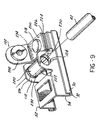
- catcher bracket means 220 is provided for transferring at least a portion of the load from the seat belt buckle mounting bracket 102 to the rear torsion member 42 thereby strengthening the attachment structure and transmitting forces imposed on the upper track 52 to the lower track 50.
- the catcher bracket means 220 preferably is in the form of a rear catcher strap or bracket 222 which may have any suitable shape besides that illustrated in Figure 9 and described hereafter.
- the shape of the rear catcher strap 222 may be varied to provide a predetermined force versus load compliance characteristic such that the rear catcher strap 222 exhibits controlled elongation under force loading.
- the rear catcher strap 222 is preferably in the form of a thin, planar strip formed to the desired shape.
- the rear catcher strap 222 is also, preferably, formed of a mild steel.
- the rear catcher strap 222 is formed of an integral, one-piece member having first and second ends, 224 and 226 respectively, bent or formed into an overlapping position substantially in registry with each other.
- Each of the first and second ends, 224 and 226 respectively, is identically constructed and has a centrally located aperture 228 formed therein.
- a first, substantially planar, portion 230 extends continuously from the first end 224 to an arcuate, generally bent-over or looped-shaped portion 232 adapted to substantially encircle the rear torsion member 42 extending through the second end 86 of the upper track 52.
- the bent-over, looped portion 232 extends continuously and integrally from the first portion 230 to a second, substantially planar, portion 234.
- the second portion 234 extends continuously to the second end 226 and is generally in registry with the first planar portion 230.
- the arcuate, loop-shaped portion 232 of the rear catcher strap 222 may or may not be in contact with the rear torsion member 42.
- the rear catcher strap 222 In normal operation of the seat adjuster 10, the rear catcher strap 222 merely rests in an inoperative position around the rear torsion tube 42. It should be noted that a similar rear catcher strap 222 could be mounted around the rear torsion bar 42 on the second end 86 of the opposite track assembly of the seat adjuster 10, if a seat belt strap dispensing mount is desired connected to the upper track of the opposite track assembly.
- the rear catcher strap In low load situations, such as those resulting from low or slow speed collisions of the vehicle having a seat adjuster 10 mounted therein, the rear catcher strap remains in a substantially inoperative condition.
- a force will be imparted by the seat belt buckle to the seat belt buckle attachment bracket 102 mounted at the rear end 86 of the upper track 52 of at least one of the track assemblies.
- This load is then transferred through the seat belt buckle bracket 102 to the upper track 52 and then along the upper track 52 to the gear box housing 142 by the mounting pin 156 attached to the upper track 52.
- the load is then transferred to the lower track 50 which is securely anchored to the vehicle floor by means of the front and rear risers, 80 and 82 respectively.
- the rear catcher bracket means 220 comes into operation.
- the loading is initially the same as that described above in that a force or load will be imparted through the seat belt buckle attachment bracket 102 to the upper track 52.
- the high load will eventually exceed the strength of the upper track, and the upper track will bend upward as shown in Figures 2 and 3.
- the rear catcher strap 222 will then transfer at least a portion of the load from the seat belt buckle bracket 102 to the rear torsion member 42, thereby increasing the ultimate load that can be carried by the structure before failure occurs.
- the rotatable seat belt buckle bracket 102 would initially be in the first position until the initial application of load rotates the bracket 102 into the second, stronger geometry position as described above. As additional load is applied to the bracket 102, the high load will eventually exceed the strength of the upper track 52, and the upper track 52 will bend upward as shown in Figures 2 and 3.
- the rear catcher strap 222 will then transfer at least a portion of the load from the seat belt buckle bracket 102 to the rear torsion member 42, thereby increasing the ultimate load that can be carried by the assembly before failure occurs.
- the load will be transferred as described above with the additional benefit of the rear catcher strap 222 transferring at least a portion of the load from the bracket 102 to the torsion member 42, thereby increasing the ultimate load that can be carried by the assembly before failure occurs.
- the rear catcher strap 222 or catcher bracket buckle brace permits higher loads during static loading and greater reliability in the buckle system.
- the manufacturing process is improved by eliminating the problems with welds previously used on the seat belt buckle bracket 102.
- Common problems with welds included no welds, cold welds, missing welds, incomplete welds and blow through weld splatter, all of which had adverse impacts on the ultimate strength of the assembly. Eliminating welds also reduces the installation processing time, by reducing part handling during the required welding operations.
- the use of the rear catcher strap 222 in place of the welded plate for the seat belt buckle bracket allows the force to be shared with the rear torsion bar 42, thereby increasing the load capable of being carried by the assembly before failure.
- the rear catcher strap 222 of the present invention preferably is used with the rotatable seat belt buckle bracket 102, sometimes referred to as a "swivel type" buckle bracket, in a power seat adjustor assembly, preferably including the front catcher strap 170 around the gear box housing as described above.
- the rear catcher strap 222 is mounted so that the inboard side of the rear torsion bar 42 slips through the loop-shaped portion 232.
- the mounted ends 224, 226 of the rear catcher strap 222 rest on top of the folded over flanges 96, 98 of the upper track 52.
- the mounted ends 224, 226 are preferably interposed on top of the flanges 96, 98 and between the upper track 52 and the buckle bracket 102.
- the tendant of the buckle bracket rivet 218 slips through the buckle bracket 102, through the catcher strap apertures 228 and finally through the upper track 52.
- the end of the rivet tendant can then be upset by means of orbital forming.
- the upper track 52 deflects upward causing the catcher strap 222 to be in tension between the buckle bracket 102 and the rear torsion bar 42. This prevents the upper track 52 from taking all of the load by sharing it with the rear torsion bar 42. The end result is higher ultimate loads for the assembly and a change in failure mode from the buckle bracket 102 to the rear riser 82.
Landscapes
- Engineering & Computer Science (AREA)
- Mechanical Engineering (AREA)
- Aviation & Aerospace Engineering (AREA)
- Transportation (AREA)
- Seats For Vehicles (AREA)
- Automotive Seat Belt Assembly (AREA)
Description
Claims (11)
- An adjustable track assembly (46, 48) supporting a seat of a vehicle from a floor pan of the vehicle, the track assembly (46, 48) includingcatcher bracket means (220) connected between the upper track (52), the seat belt buckle attachment means (102, 220) and the torsion member (42) for transferring at least a portion of a high load force through the seat belt buckle (210) and the upper track (52) to the torsion member (42).an inboard lower track (50) and an outboard lower track (50) adapted to be anchored to the floorpan of the vehicle in a stationary manner,an inboard upper track (52) and an outboard upper track (52) adapted to support the seat, wherein the inboard and outboard upper tracks (52) are movably mounted with respect to the inboard and outboard lower tracks (50),means (34, 40, 144, 160) for selectively, reciprocally adjusting each upper track (52) with fore and aft movement relative to the corresponding stationary lower track (50),at least one torsion member (42, 44) connected between the inboard and outboard upper tracks (52),a seat belt buckle (210) and seat belt buckle attachment means (102, 220) having one portion adapted to be connected to a seat belt buckle (210) and another portion attachable to the upper track (52), wherein the seat belt buckle attachment means (102, 220) are characterized by
- The assembly (46, 48) according to claim 1,
wherein the catcher bracket means (220) are further characterized by
an elongated catcher strap (222) having first and second ends (224, 226) with apertures (228) formed adjacent each end, the catcher strap (222) having a longitudinally extending loop (232), such that the aperture (228) in the first end (224) is disposed coaxially with respect to the aperture (228) in the second end (226) and the loop (232) is disposed around the torsion member (42), and a fastener, disposed through the coaxial apertures (228) of the catcher strap (222), for connecting the seat belt buckle (210) to the upper track (52). - The assembly (46, 48) according to claim 1 or 2,
wherein the seat belt buckle attachment means (102, 220) are further characterized by
an attachment member (102) having first and second angularly disposed legs (200, 202), the second leg (202) adapted to be connected to the seat belt buckle (210); and fixing means (218) for fixedly attaching catcher bracket means (220) and the first leg (200) of the attachment member (102) to the upper track (52) in a fixed, normal operating position and for allowing rotation of the attachment member (102) with respect to the fixing means (218) for fixedly attaching to a second position relative to the upper track (52) in response to a predetermined force applied to the attachment member (102) through the seat belt buckle (210), wherein the first and second legs (200, 202) of the attachment member (102) are placed in tension when in the second position. - The assembly (46, 48) according to claim 3,
wherein the attachment member (102) is an integral, one-piece attachment member (102). - The assembly (46, 48) according to claim 3 or 4,
wherein the second leg (202) of the attachment member (102) is disposed at an obtuse angle with respect to the first leg (200) thereof. - The assembly (46, 48) according to claim 5,
wherein in the first, normal operating position, the second leg (202) extends upwards from a side wall (94) of the upper track (52). - The assembly (46, 48) according to claim 6,
wherein in the second position, the second leg (202) of the attachment member (102) is substantially coaxial with the longitudinal axis of the upper track (52). - The assembly (46, 48) according to any of claims 3 to 7,
wherein the fixing means (218) for fixedly attaching further comprises:a rivet (218) mounted through an aperture (228) in the first leg (200) of the attachment member (102) and a coaxial aperture formed in the upper track (52). - The assembly (46, 48) according to any of claims 1 to 8, further comprising:
front catcher bracket means (170) connected between the upper track (52) and the lower track (50) for transmitting high load forces imparted to the upper track (52) to the lower track (50), the high load forces tending to move the upper track (52) in a forward direction with respect to the lower track (50). - The assembly (46, 48) according to claim 9,
wherein the front catcher bracket means (170) further comprises:an elongated front catcher strap (170) having first and second ends (172, 174) and a longitudinally extending loop (182) between the first and second ends (172, 174), the loop (182) disposed around the front torsion member (44) and the ends (172, 174) connected to the lower track (50). - The assembly (46, 48) according to claim 9 or 10,
further comprising:a power seat apparatus for the vehicle having inboard and outboard spaced track assemblies (46, 48), each track assembly (46, 48) formed of the lower track (50) fixedly mounted to the vehicle floor and the upper track (52) slidably disposed within each lower track;a front tubular torsion member (44) connected between the upper tracks (52) of the inboard and outboard track assemblies (46, 48);the attachment member (102) further including a seat belt buckle attachment member (102) connected to a rear portion of the inboard upper track (52);a drive motor having first and second rotatable output shafts (40), the output shafts (40) respectively extending towards opposite inboard and outboard upper tracks (52);a lead screw (144) disposed between each upper and lower track (50; 52);a drive block (160) fixedly mounted to each lower track (50) and threadingly engaging the lead screw (144);gear means (140) fixedly mounted to each upper track (52) and coupling one of the motor output shafts (40) to one lead screw (144), the gear means (140) including a plurality of meshingly engaged gears, at least one gear (152) formed of a plastic material and having a metallic inner annular member (154) fixedly attached to the lead screw (144);and front catcher bracket means (170), disposed in a force transmitting position between the front torsion member (44) of each upper track (52) and each lead screw (144) associated therewith, for transmitting high load forces imparted on the upper track (52) around and bypassing the gear means (140), wherein the high impact forces tend to move the upper track (52) in a forward direction with respect to the lead screw (144).
Applications Claiming Priority (3)
| Application Number | Priority Date | Filing Date | Title |
|---|---|---|---|
| US08/177,257 US5507552A (en) | 1994-01-04 | 1994-01-04 | Rotatable seat belt buckle mounting bracket for a vehicle seat adjuster with a catcher bracket buckle brace |
| US177257 | 1994-01-04 | ||
| PCT/US1994/014844 WO1995018731A1 (en) | 1994-01-04 | 1994-12-29 | Rotatable seat belt buckle mounting bracket for a wehicle seat adjuster with a catcher bracket buckle brace |
Publications (2)
| Publication Number | Publication Date |
|---|---|
| EP0735960A1 EP0735960A1 (en) | 1996-10-09 |
| EP0735960B1 true EP0735960B1 (en) | 2000-05-03 |
Family
ID=22647869
Family Applications (1)
| Application Number | Title | Priority Date | Filing Date |
|---|---|---|---|
| EP95909207A Expired - Lifetime EP0735960B1 (en) | 1994-01-04 | 1994-12-29 | Rotatable seat belt buckle mounting bracket for a wehicle seat adjuster with a catcher bracket buckle brace |
Country Status (5)
| Country | Link |
|---|---|
| US (1) | US5507552A (en) |
| EP (1) | EP0735960B1 (en) |
| CA (1) | CA2180451C (en) |
| DE (1) | DE69424312T2 (en) |
| WO (1) | WO1995018731A1 (en) |
Cited By (1)
| Publication number | Priority date | Publication date | Assignee | Title |
|---|---|---|---|---|
| CN107428272A (en) * | 2015-04-14 | 2017-12-01 | 株式会社泰极爱思 | vehicle seat |
Families Citing this family (20)
| Publication number | Priority date | Publication date | Assignee | Title |
|---|---|---|---|---|
| DE29513272U1 (en) † | 1995-08-18 | 1997-01-02 | Robert Bosch Gmbh, 70469 Stuttgart | Device for adjusting a seat in a motor vehicle |
| US5797293A (en) * | 1996-12-19 | 1998-08-25 | Lear Corporation | Plastic drive block for vehicle seat adjuster |
| US5860319A (en) * | 1996-12-19 | 1999-01-19 | Lear Corporation | Reduced noise drive block for vehicle seat adjuster |
| US6089665A (en) * | 1998-07-02 | 2000-07-18 | Dura Automotive Properties Inc. | Load transfer structural member for a seat assembly |
| US6264158B1 (en) * | 1998-12-09 | 2001-07-24 | Dura Global Technologies, Inc | Structural support for seat track assembly |
| US6405987B1 (en) | 1999-08-05 | 2002-06-18 | Dura Global Technologies, Inc. | Reinforcement member for a seat mounting assembly |
| DE60316483T2 (en) * | 2002-01-23 | 2008-07-03 | Delta Kogyo Co. Ltd. | Motorically adjustable vehicle seat |
| EP1357312A1 (en) * | 2002-04-26 | 2003-10-29 | N.V. Bekaert S.A. | A force-limiting energy absorber |
| FR2876963B1 (en) * | 2004-10-21 | 2007-01-26 | Faurecia Sieges Automobile | VEHICLE COMPRISING A SEAT CONTROL BY A MOTOR WITH ASYMMETRIC FEATURES |
| FR2880311B1 (en) * | 2005-01-05 | 2008-07-18 | Faurecia Sieges Automobile | MOTOR VEHICLE SEAT EQUIPPED WITH AN ELASTIC RECALL OF THE DOSSIER |
| DE102006038771A1 (en) * | 2006-08-17 | 2008-02-21 | Recaro Aircraft Seating Gmbh & Co. Kg | seat device |
| US8038210B2 (en) * | 2008-09-23 | 2011-10-18 | Cvg Management Corporation | Vehicle seating system with pivoting stop mechanism and method |
| US8439448B2 (en) | 2010-08-17 | 2013-05-14 | Toyota Motor Engineering & Manufacturing North America, Inc. | Buckle for center occupant for bench seat with extended travel |
| PL2644443T3 (en) * | 2010-11-22 | 2015-12-31 | Johnson Controls Tech Co | Vehicle seat |
| JP6977476B2 (en) * | 2017-10-24 | 2021-12-08 | トヨタ紡織株式会社 | Cushion frame |
| US10525929B2 (en) | 2018-02-27 | 2020-01-07 | Ford Global Technologies, Llc | Seatbelt assembly |
| US10543806B2 (en) | 2018-02-27 | 2020-01-28 | Ford Global Technologies, Llc | Seatbelt assembly |
| US10434976B2 (en) | 2018-02-27 | 2019-10-08 | Ford Global Technologies, Llc | Seatbelt assembly |
| US10518740B2 (en) | 2018-02-27 | 2019-12-31 | Ford Global Technologies, Llc | Seatbelt assembly |
| JP7058578B2 (en) * | 2018-09-14 | 2022-04-22 | トヨタ車体精工株式会社 | Seat slide device |
Family Cites Families (46)
| Publication number | Priority date | Publication date | Assignee | Title |
|---|---|---|---|---|
| GB783800A (en) * | 1955-03-18 | 1957-10-02 | Rolls Royce | Vehicle seats |
| US3106989A (en) * | 1962-03-06 | 1963-10-15 | Airborne Accessories Corp | Energy absorbing devices |
| US3457234A (en) * | 1966-11-18 | 1969-07-22 | Uniroyal Inc | Polyurethane elastoplastic resistant to high speed flexural impact and gear made therefrom |
| GB1428679A (en) * | 1972-08-19 | 1976-03-17 | Rover Co Ltd | Vehicle seating |
| DE2545763B2 (en) * | 1975-10-13 | 1979-06-21 | Ausscheidung in: 25 59 653 C Rob. Hammerstein GmbH, 5650 Solingen | Gleitschlenenfiihnuig for longitudinally movable vehicle seats |
| DE2806998A1 (en) * | 1978-02-18 | 1979-08-30 | Hammerstein Gmbh C Rob | SLIDE RAIL GUIDE |
| DE2826634A1 (en) * | 1978-06-19 | 1980-01-03 | Daimler Benz Ag | LOCKING RAIL SUPPORTED ON A FIXED VEHICLE PART |
| US4274293A (en) * | 1979-05-23 | 1981-06-23 | International Telephone And Telegraph Corporation | Drive block structure for an adjustable vehicle seat track |
| US4448381A (en) * | 1980-01-14 | 1984-05-15 | International Telephone And Telegraph Corporation | Motor mount structure for vehicle seat adjustment apparatus |
| EP0037726A1 (en) * | 1980-04-03 | 1981-10-14 | Ti Cox Limited | Improvements in or relating to vehicle seat slides |
| JPS57178954A (en) * | 1981-04-30 | 1982-11-04 | Isuzu Motors Ltd | Guide apparatus of car seat belt |
| DE3312480C2 (en) * | 1983-04-07 | 1986-06-12 | Daimler-Benz Ag, 7000 Stuttgart | Seat belt anchorage for a longitudinally adjustable vehicle seat |
| US4487459A (en) * | 1983-07-01 | 1984-12-11 | General Motors Corporation | Seat slide structure |
| JPS6167266U (en) * | 1984-10-09 | 1986-05-08 | ||
| JPS6175362U (en) * | 1984-10-23 | 1986-05-21 | ||
| DE3439076A1 (en) * | 1984-10-25 | 1986-04-30 | Bayerische Motoren Werke AG, 8000 München | Seatbelt arrangement, in particular for the rear seat of a motor vehicle |
| DE3444483A1 (en) * | 1984-12-06 | 1986-06-12 | Dr.Ing.H.C. F. Porsche Ag, 7000 Stuttgart | LOCKING DEVICE FOR SLIDING VEHICLE SEATS |
| DE3684498D1 (en) * | 1985-02-22 | 1992-04-30 | Dunlop Cox Ltd | ADJUSTMENT DEVICE FOR VEHICLE SEATS. |
| US4572469A (en) * | 1985-03-11 | 1986-02-25 | General Motors Corporation | Latching arrangement for seat slide structures |
| JPS61158538U (en) * | 1985-03-26 | 1986-10-01 | ||
| FR2580759B1 (en) * | 1985-04-18 | 1990-02-23 | Marchal Equip Auto | DEVICE FOR CONTROLLING THE MOVEMENT OF AN ELEMENT, PARTICULARLY A SEAT OR PARTS OF A SEAT OF A MOTOR VEHICLE, RELATIVE TO A CONSTRUCTION |
| NO157647C (en) * | 1985-12-06 | 1988-04-27 | Loyd S Industri As | SAFETY BELT SYSTEM WITH FLEXIBLE MOUNTING DEVICE. |
| JPS62210143A (en) * | 1986-03-11 | 1987-09-16 | Nissan Motor Co Ltd | Seat slide rail structure for automobile |
| JPH0615312B2 (en) * | 1986-04-07 | 1994-03-02 | 株式会社大井製作所 | Seat slide device for automobile |
| DE3614457C2 (en) * | 1986-04-29 | 1996-05-23 | Lear Seating Gmbh & Co Kg | Motor vehicle seat |
| JPS6334252A (en) * | 1986-07-30 | 1988-02-13 | Aisin Seiki Co Ltd | Power seat device for automobile |
| JPS6338048A (en) * | 1986-07-31 | 1988-02-18 | Oi Seisakusho Co Ltd | Power seat sliding device |
| FR2610063B1 (en) * | 1987-01-27 | 1991-01-25 | Faure Ste Financiere Bertrand | IMPROVEMENTS IN SCREW POSITION ADJUSTMENT MECHANISMS |
| JPH0537883Y2 (en) * | 1987-03-03 | 1993-09-24 | ||
| GB8708934D0 (en) * | 1987-04-14 | 1987-05-20 | Autoliv Gmbh | Vehicle seat belt connecting arrangement |
| DE3715861A1 (en) * | 1987-05-12 | 1988-12-01 | Ase Deutschland Gmbh | Device for tightening a safety belt |
| CA1293680C (en) * | 1987-07-13 | 1991-12-31 | William Joseph John Harney | Powered seat adjustor and components thereof |
| US4832409A (en) * | 1987-09-08 | 1989-05-23 | General Motors Corporation | Restraint belt load capacity fore and aft power seat adjuster apparatus |
| FR2623586B1 (en) * | 1987-11-20 | 1990-04-20 | Rockwell Cim | TELESCOPIC SCREW WITH SCREW FOR ADJUSTING AN ELEMENT SUCH AS A VEHICLE SEAT |
| JPH0636995Y2 (en) * | 1988-03-24 | 1994-09-28 | アイシン精機株式会社 | Seat rail |
| DE3836248A1 (en) * | 1988-10-25 | 1990-04-26 | Keiper Recaro Gmbh Co | SEAT RAIL FOR VEHICLE SEATS, IN PARTICULAR MOTOR VEHICLE SEATS |
| US4964608A (en) * | 1989-02-09 | 1990-10-23 | Hoover Universal, Inc. | Vehicle seat adjuster with integral positive locking traveling seat belt anchorage |
| JP2780320B2 (en) * | 1989-03-31 | 1998-07-30 | アイシン精機株式会社 | Power seat slide device for automobile |
| US4939945A (en) * | 1989-04-13 | 1990-07-10 | Ryder International Corp. | Gearbox drive system with plastic output gear |
| FR2648767B1 (en) * | 1989-06-22 | 1991-10-11 | Faure Bertrand Automobile | IMPROVEMENTS IN LONGITUDINAL ADJUSTMENT MECHANISMS OF VEHICLE SEATS |
| US5048787A (en) * | 1990-04-10 | 1991-09-17 | Tachi-S Co., Ltd. | Slide rail for automotive seat |
| JPH0732249Y2 (en) * | 1990-05-29 | 1995-07-26 | 池田物産株式会社 | Power seat slide device |
| JPH0450536A (en) * | 1990-06-15 | 1992-02-19 | Oi Seisakusho Co Ltd | Reduction gear |
| US5102197A (en) * | 1990-11-09 | 1992-04-07 | Tacki-S Co., Ltd. | Seat slide device |
| US5076529A (en) * | 1991-01-29 | 1991-12-31 | Atwood Industries, Inc. | Seat adjuster with improved crash resistance |
| US5303983A (en) * | 1992-04-30 | 1994-04-19 | Itt Corporation | Rotatable seat belt buckle mounting bracket for vehicle seat adjuster |
-
1994
- 1994-01-04 US US08/177,257 patent/US5507552A/en not_active Expired - Lifetime
- 1994-12-29 CA CA002180451A patent/CA2180451C/en not_active Expired - Fee Related
- 1994-12-29 WO PCT/US1994/014844 patent/WO1995018731A1/en not_active Ceased
- 1994-12-29 DE DE69424312T patent/DE69424312T2/en not_active Expired - Fee Related
- 1994-12-29 EP EP95909207A patent/EP0735960B1/en not_active Expired - Lifetime
Cited By (3)
| Publication number | Priority date | Publication date | Assignee | Title |
|---|---|---|---|---|
| CN107428272A (en) * | 2015-04-14 | 2017-12-01 | 株式会社泰极爱思 | vehicle seat |
| US10421377B2 (en) | 2015-04-14 | 2019-09-24 | Tachi-S Co., Ltd. | Vehicle seat |
| CN107428272B (en) * | 2015-04-14 | 2019-10-15 | 株式会社泰极爱思 | vehicle seat |
Also Published As
| Publication number | Publication date |
|---|---|
| WO1995018731A1 (en) | 1995-07-13 |
| DE69424312T2 (en) | 2001-02-01 |
| US5507552A (en) | 1996-04-16 |
| CA2180451A1 (en) | 1995-07-13 |
| DE69424312D1 (en) | 2000-06-08 |
| EP0735960A1 (en) | 1996-10-09 |
| CA2180451C (en) | 1999-02-16 |
Similar Documents
| Publication | Publication Date | Title |
|---|---|---|
| US5507552A (en) | Rotatable seat belt buckle mounting bracket for a vehicle seat adjuster with a catcher bracket buckle brace | |
| US5316258A (en) | Power seat adjuster with drive gear force bypass | |
| CA2118415C (en) | One-piece upper track for a power seat adjuster | |
| US5303983A (en) | Rotatable seat belt buckle mounting bracket for vehicle seat adjuster | |
| US4804226A (en) | Deformation-resistant frame for seats of motor vehicles | |
| EP1245464B1 (en) | Seatback frame for vehicle seat | |
| EP0696526B1 (en) | A vehicle seat assembly | |
| CA2392891C (en) | Shock absorbing vehicle seat frame | |
| US5318341A (en) | Vehicle seat assembly with structural seat back to accommodate seat belt loads applied to seat back | |
| US5467957A (en) | Vehicle power seat adjuster with self-aligning drive nut | |
| US5456439A (en) | Vehicle power seat adjuster with self-aligning lead screw actuator | |
| US5575531A (en) | Vehicle power seat adjuster with end driven lead screw actuation | |
| US5795024A (en) | Clam-shell pivot assembly for a structured vehicle seat | |
| EP0627996A1 (en) | High strength motor vehicle seat recliner | |
| JPH04252744A (en) | Power seat slide device | |
| JPH07503212A (en) | High strength automobile seat frame and method | |
| US20060261625A1 (en) | Device for fixing a belt lock of a safety belt on a vehicle seat | |
| GB2183988A (en) | Device for attaching a safety belt to a vehicle seat | |
| EP1070640B1 (en) | Seat belt pretensioner device powered by vehicle body deformation | |
| WO1997004986A1 (en) | Track for seat belt restraint system |
Legal Events
| Date | Code | Title | Description |
|---|---|---|---|
| PUAI | Public reference made under article 153(3) epc to a published international application that has entered the european phase |
Free format text: ORIGINAL CODE: 0009012 |
|
| 17P | Request for examination filed |
Effective date: 19960805 |
|
| AK | Designated contracting states |
Kind code of ref document: A1 Designated state(s): DE FR GB |
|
| 17Q | First examination report despatched |
Effective date: 19970912 |
|
| RAP1 | Party data changed (applicant data changed or rights of an application transferred) |
Owner name: LEAR CORPORATION |
|
| GRAG | Despatch of communication of intention to grant |
Free format text: ORIGINAL CODE: EPIDOS AGRA |
|
| GRAG | Despatch of communication of intention to grant |
Free format text: ORIGINAL CODE: EPIDOS AGRA |
|
| GRAH | Despatch of communication of intention to grant a patent |
Free format text: ORIGINAL CODE: EPIDOS IGRA |
|
| GRAH | Despatch of communication of intention to grant a patent |
Free format text: ORIGINAL CODE: EPIDOS IGRA |
|
| GRAA | (expected) grant |
Free format text: ORIGINAL CODE: 0009210 |
|
| AK | Designated contracting states |
Kind code of ref document: B1 Designated state(s): DE FR GB |
|
| PG25 | Lapsed in a contracting state [announced via postgrant information from national office to epo] |
Ref country code: FR Free format text: LAPSE BECAUSE OF FAILURE TO SUBMIT A TRANSLATION OF THE DESCRIPTION OR TO PAY THE FEE WITHIN THE PRESCRIBED TIME-LIMIT Effective date: 20000503 |
|
| REF | Corresponds to: |
Ref document number: 69424312 Country of ref document: DE Date of ref document: 20000608 |
|
| EN | Fr: translation not filed | ||
| PG25 | Lapsed in a contracting state [announced via postgrant information from national office to epo] |
Ref country code: GB Free format text: LAPSE BECAUSE OF NON-PAYMENT OF DUE FEES Effective date: 20001229 |
|
| PLBE | No opposition filed within time limit |
Free format text: ORIGINAL CODE: 0009261 |
|
| STAA | Information on the status of an ep patent application or granted ep patent |
Free format text: STATUS: NO OPPOSITION FILED WITHIN TIME LIMIT |
|
| 26N | No opposition filed | ||
| GBPC | Gb: european patent ceased through non-payment of renewal fee |
Effective date: 20001229 |
|
| PGFP | Annual fee paid to national office [announced via postgrant information from national office to epo] |
Ref country code: DE Payment date: 20080131 Year of fee payment: 14 |
|
| PG25 | Lapsed in a contracting state [announced via postgrant information from national office to epo] |
Ref country code: DE Free format text: LAPSE BECAUSE OF NON-PAYMENT OF DUE FEES Effective date: 20090701 |