EP0735259B1 - Engine air/fuel control system - Google Patents
Engine air/fuel control system Download PDFInfo
- Publication number
- EP0735259B1 EP0735259B1 EP96301409A EP96301409A EP0735259B1 EP 0735259 B1 EP0735259 B1 EP 0735259B1 EP 96301409 A EP96301409 A EP 96301409A EP 96301409 A EP96301409 A EP 96301409A EP 0735259 B1 EP0735259 B1 EP 0735259B1
- Authority
- EP
- European Patent Office
- Prior art keywords
- upstream
- signal
- downstream
- amplitude
- sensor
- Prior art date
- Legal status (The legal status is an assumption and is not a legal conclusion. Google has not performed a legal analysis and makes no representation as to the accuracy of the status listed.)
- Expired - Lifetime
Links
Images





Classifications
-
- F—MECHANICAL ENGINEERING; LIGHTING; HEATING; WEAPONS; BLASTING
- F01—MACHINES OR ENGINES IN GENERAL; ENGINE PLANTS IN GENERAL; STEAM ENGINES
- F01N—GAS-FLOW SILENCERS OR EXHAUST APPARATUS FOR MACHINES OR ENGINES IN GENERAL; GAS-FLOW SILENCERS OR EXHAUST APPARATUS FOR INTERNAL-COMBUSTION ENGINES
- F01N11/00—Monitoring or diagnostic devices for exhaust-gas treatment apparatus
- F01N11/007—Monitoring or diagnostic devices for exhaust-gas treatment apparatus the diagnostic devices measuring oxygen or air concentration downstream of the exhaust apparatus
-
- F—MECHANICAL ENGINEERING; LIGHTING; HEATING; WEAPONS; BLASTING
- F01—MACHINES OR ENGINES IN GENERAL; ENGINE PLANTS IN GENERAL; STEAM ENGINES
- F01N—GAS-FLOW SILENCERS OR EXHAUST APPARATUS FOR MACHINES OR ENGINES IN GENERAL; GAS-FLOW SILENCERS OR EXHAUST APPARATUS FOR INTERNAL-COMBUSTION ENGINES
- F01N2550/00—Monitoring or diagnosing the deterioration of exhaust systems
- F01N2550/02—Catalytic activity of catalytic converters
-
- F—MECHANICAL ENGINEERING; LIGHTING; HEATING; WEAPONS; BLASTING
- F01—MACHINES OR ENGINES IN GENERAL; ENGINE PLANTS IN GENERAL; STEAM ENGINES
- F01N—GAS-FLOW SILENCERS OR EXHAUST APPARATUS FOR MACHINES OR ENGINES IN GENERAL; GAS-FLOW SILENCERS OR EXHAUST APPARATUS FOR INTERNAL-COMBUSTION ENGINES
- F01N2900/00—Details of electrical control or of the monitoring of the exhaust gas treating apparatus
- F01N2900/04—Methods of control or diagnosing
- F01N2900/0421—Methods of control or diagnosing using an increment counter when a predetermined event occurs
-
- Y—GENERAL TAGGING OF NEW TECHNOLOGICAL DEVELOPMENTS; GENERAL TAGGING OF CROSS-SECTIONAL TECHNOLOGIES SPANNING OVER SEVERAL SECTIONS OF THE IPC; TECHNICAL SUBJECTS COVERED BY FORMER USPC CROSS-REFERENCE ART COLLECTIONS [XRACs] AND DIGESTS
- Y02—TECHNOLOGIES OR APPLICATIONS FOR MITIGATION OR ADAPTATION AGAINST CLIMATE CHANGE
- Y02T—CLIMATE CHANGE MITIGATION TECHNOLOGIES RELATED TO TRANSPORTATION
- Y02T10/00—Road transport of goods or passengers
- Y02T10/10—Internal combustion engine [ICE] based vehicles
- Y02T10/40—Engine management systems
Definitions
- the invention relates to electronic engine controls for internal combustion engines.
- it relates to air/fuel control with catalytic converter monitoring.
- Engine air/fuel control systems are known in which fuel delivered to the engine is adjusted by output signals derived from exhaust gas oxygen sensors positioned both upstream and downstream of the catalytic converter. Each output signal is generated by comparing the voltage output of each sensor against a reference to generate a two-state signal.
- the inventors herein have recognised numerous problems with the above approaches. For example, poor engine calibration, or peculiar mixing of the exhaust gases in the exhaust manifold, may cause the downstream sensor to be exposed to exhaust gases rich of stoichiometry. A comparison of the downstream sensor output to a reference voltage may not always be possible. Under such conditions, a transition in the sensor output may not be detected thereby reducing the accuracy of converter efficiency indications. Similar problems may occur when the peak-to-peak voltage output of the sensors becomes degraded.
- An object of the invention herein is to provide catalytic converter efficiency indications from downstream and upstream exhaust gas oxygen sensors independently of the conventional two-state output signal provided from such sensors.
- the control method comprises the steps of: delivering fuel to the engine in proportion to a fuel signal; adjusting the fuel signal with a feedback variable derived from a comparison of a reference amplitude to output amplitude of an upstream exhaust gas oxygen sensor positioned upstream of the converter; biasing the fuel signal in relation to a biasing signal derived from a comparison of a reference value to an output amplitude of a downstream exhaust gas oxygen sensor positioned downstream of the converter; generating a difference in amplitude of the downstream sensor output amplitude each sample period; storing downstream sensor output amplitude as a peak amplitude each sample period when the downstream sensor amplitude difference changes signs; indicating a downstream sensor transition when the downstream sensor difference changes signs and a difference between the stored peak value and the stored peak value stored during a previous change in the
- An advantage of the above aspect of the invention is that exhaust gas oxygen sensor transitions are provided independently of the conventional sensor two-state signal. More accurate indications of converter efficiency are thereby provided than heretofore possible.
- Controller 10 is shown including a conventional microcomputer including: microprocessor unit 12; input ports 14; output ports 16; read only memory 18, for storing the controlled program; random access memory 20, for temporary data storage which may also be used for counters or timers; keep alive memory 22, for storing learned values; and a conventional data bus. Outputs are shown coupled to conventional electronic drivers 18.
- Controller 10 is shown receiving various signals from sensors coupled to engine 28 including: measurement of inducted mass air flow (MAF) from air flow sensor 32, engine coolant temperature (T) from temperature sensor 40; and indication of engine speed (RPM) from tachometer 42.
- MAF inducted mass air flow
- T engine coolant temperature
- RPM engine speed
- Output signal FEGO1 is provided from conventional exhaust gas oxygen sensor 44 coupled to right hand exhaust manifold 56 which, in this particular example, is coupled to the right hand cylinder bank of a V-8 engine.
- output signal FEGO2 is shown provided by conventional exhaust gas oxygen sensor 55 coupled to left hand exhaust manifold 57. Both signal FEGO1 and signal FEGO2 are compared to a respective reference value selected at the midpoint of the sensor's average peak-to-peak output in respective comparators 48 and 49. Respective signals FEGO1S and FEGO2S are thereby generated. Both signal FEGO1S and signal FEGO2S are two-state signals having a predetermined high voltage when exhaust gases are rich of stoichiometry and a predetermined low voltage when exhaust gases are lean of stoichiometry.
- Another conventional exhaust gas oxygen sensor 52 is shown coupled to the engine exhaust downstream of catalytic converter 50, sensor 52 provides signal REGO to controller 10 which is related to oxygen content in the exhaust gases.
- Output signal REGO is also compared to a reference value associated with its midpoint to provide two-state output signal REGOS to controller 10.
- Signal REGOS is a preselected high voltage when exhaust gas downstream of catalytic converter 50 are rich of stoichiometry and a low selected voltage when such exhaust gases are lean of stoichiometry.
- Intake manifold 58 and intake manifold 59 are respectively coupled to the right hand cylinder bank and left hand cylinder bank of engine 28 and are also shown communicating with respective throttle body 60 and throttle body 61. Each throttle body in turn is shown connected to single air intake 64. Throttle plate 62 and mass air flow sensor 32 are shown coupled to air intake 64.
- conventional electronic fuel injectors 76 and 77 are shown coupled to respective throttle body 60 and throttle body 61.
- Fuel injectors 76 delivers fuel in response in proportion to the pulse width of signal fpwl from controller 10 via one of the conventional electronic drivers 18.
- fuel injector 77 delivers fuel in proportion to the pulse width of signal fpw2 from controller 10 via one of the electronic drivers 18.
- Fuel is delivered to fuel injectors 76 and 77 by a conventional fuel system including fuel tank 80, fuel pump 82, and fuel rail 84.
- CFI central fuel injected
- step 104 a flow chart of a routine performed by controller 10 to generate fuel trim signal FT is now described.
- the routine is entered after closed loop air/fuel control is commenced (step 104) in response to preselected engine operating conditions such as temperature.
- closed loop control commences signal REGOS is read from comparator 54 (step 108) and subsequently processed in the proportional plus integral control described below.
- preselected proportional term Pj is subtracted from fuel trim signal FT (step 120).
- preselected integral term Dj is subtracted from fuel trim signal FT (step 122).
- step 116 when signal REGOS is high (step 116), and was also high during the previous background loop of controller 10 (step 124), integral term Ai, is added to fuel trim signal FT (step 126).
- step 116 when signal REGOS is high, (step 116), but was low during the previous background loop (step 124), proportional term Pi is added to fuel trim signal FT (step 128).
- fuel trim signal FT is generated from a proportional plus integral controller responsive to exhaust gas oxygen sensor 52.
- the integration steps for integrating signal REGOS in a direction to cause a lean air/fuel correction are provided by integration steps Di, and the proportional term for such correction provided by Pi.
- integral term Dj and proportional term Pj cause rich air/fuel corrections.
- a separate fuel delivering and fuel adjusting routine is executed by controller 10 for both the left hand cylinder bank and the right hand cylinder bank.
- an open loop fuel quantity is first determined by dividing the measurement of inducted mass air flow (MAF) by desired air/fuel ratio AFd which is typically the stoichiometric value for gasoline combustion (step 158r).
- This open loop fuel charge is then adjusted, in this example divided, by feedback variable FV1.
- the resulting desired quantity of fuel expressed as signal Fd1, is then converted into corresponding pulse width signal fpw1 (step 159r).
- step 160r After determining that closed loop control is desired (step 160r), by monitoring engine operating conditions such as temperature (T), signal FEGO1S is read during step 162r. During step 164r, fuel trim signal FT is transferred from the routine previously described with reference to Figure 2.
- Proportional term Pi or proportional term Pj are selected for achieving the desired air/fuel biasing indicated by fuel trim signal FT (step 165r). For example, in the event a lean air/fuel bias is required, proportional term Pi is increased. Conversely, if a rich air/fuel bias is required, proportional term Pj is increased in proportion to fuel trim signal FT.
- air fuel biases may also be achieved by decreasing the proportional terms, increasing the integral terms, or decreasing the integral terms by an amount necessary to achieve the air/fuel bias.
- preselected proportional term Pj is subtracted from feedback variable FV1 (step 170r).
- preselected integral term ⁇ i is subtracted from feedback variable FV1 (step 172r).
- Integral term Dj is added to feedback variable FV1 (step 176r), when signal FEGO1S is high (step 166r), and was also high during the previous background loop of controller 10 (step 174r).
- proportional term Pi is added to feedback variable FV1 (step 178r).
- feedback variable FV1 is generated from the proportional plus integral controller (PI) responsive to two-state signal FEGO1S derived from upstream exhaust gas oxygen sensor 44.
- PI proportional plus integral controller
- controller 10 to: generate the desired quantity of liquid fuel delivered to engine 28 (fuel signal Fd2 and pulse width signal fpw2); and trim the desired fuel quantity by feedback variable FV2 which is related to both two-state signal FEGOIS and fuel trim signal FT.
- the routines executed by controller 10 for delivering fuel to left intake manifold 59 is described in process steps 158L-178L shown in Figures 4A-4B. These process steps are substantially the same as those previously described with respect to delivering fuel to right hand intake manifold 58 with particular reference to Figures 3A-3B wherein like numerals refer to like process steps and like components.
- FIG. 5A-5B the routine for indicating transitions in the output of the upstream exhaust gas oxygen sensors are now provided.
- a Y-pipe exhaust manifold is coupled to a single catalytic converter
- inferred upstream signal is generated (FEGOI).
- Inferred upstream signal FEGOI corresponds to a hypothetical single exhaust gas oxygen sensor positioned upstream of converter 50.
- the routine described herein is also applicable to a single exhaust gas oxygen sensor positioned upstream of converter 50.
- inferred signal FEGOI is set equal to output voltage amplitude FEGO1 from sensor 44 (step 214), when signal FEGO1 is greater than signal FEGO2 (step 204) and a Y-pipe exhaust manifold configuration is utilised (step 200).
- inferred signal FEGO1 is set equal to output voltage FEGO2 (step 210).
- inferred signal FEGOI is set equal to the output voltage of the single exhaust gas oxygen sensor (sensor 44 in this particular example) as shown in step 214.
- step 216 the difference between inferred signal FEGOIi during the present background loop (i) of controller 10 and inferred signal FEGOI i-1 from the previous background loop (i-1) is taken to generate signal DELTAI i .
- the sign of signal DELTAI i is stored as signal SLOPESGN during step 220.
- inferred signal FEGOI i-1 from the preceding background loop continues to be stored as signal FEGOIi for this background loop (step 226) and the subroutine exited during step 220.
- signal SLOPE is set equal to "1" (232).
- Signal SLOPE is set equal to "0" (234) when the slope of signal DELTAI i is negative (228) and the absolute value of signal DELTAI i is less than deadband value DBAND (224).
- inferred signal FEGOI i is stored as a peak value (signal PEAK) during the present background loop (i) as shown in step 242.
- transition flag TRANSFEGOI for inferred signal FEGOI is set during step 250 and this routine exited.
- the output amplitude of signal REGO is read during step 314.
- step 316 the difference between signal REGOi during the present background loop (i) of controller 10 and signal REGO i-1 from the previous background loop (i-1) is taken to generate signal DELTAR i .
- the sign of signal DELTAR i is stored as signal SLOPESGN during step 320.
- signal REGO i-1 from the preceding background loop continues to be stored as signal REGO i for this background loop (step 326) and the subroutine exited during step 320.
- signal SLOPE is set equal to "1" (332).
- Signal SLOPE is set equal to "0" (334) when the slope of signal DELTAR i is negative (328) and the absolute value of signal DELTAR i is less than deadband value DBAND (324).
- signal REGO i is stored as a peak value (signal PEAK) during the present background loop (i) as shown in step 342.
- transition flag TRANSREGO for signal REGO is set during step 350 and this routine exited.
- step 690 initial engine conditions are checked before entering the test cycle described below. More specifically, engine temperature (T) should be within a predetermined range, a predetermined time should have elapsed since the engine was started, and closed loop air/fuel control should have been operable for at least a preselected time.
- T engine temperature
- inferred signal FEGOI is read (step 594) from the subroutine previously described with reference to Figures 5A-5B.
- Inferred signal FEGOI is an inference of an output from a hypothetical exhaust gas oxygen sensor exposed to a hypothetical blended mixture of exhaust gases from right hand exhaust manifold 56 and left hand exhaust manifold 57.
- the inducted air flow range in which engine 28 is operating is determined during steps 700, 704, and 706. These ranges are described as range (1), range (2), and range (n) for this particular example wherein "n" inducted air flow ranges are used to advantage. Assuming engine operation is within air flow range (1), transitions between states of inferred signal FEGOI are counted to generate count signal CIE 1 . This count is compared to maximum count CIE 1max during step 712. While engine operation remains within air flow range (1), a test period of predetermined duration is generated by incrementing count CIE 1 each transition of signal FEGOI until count CIE 1 is equal to maximum count CIE 1max (step 716).
- count CR 1 is incremented each transition of signal REGOS (step 718). Stated another way, count CR 1 is increment each transition of signal REGOS until count CIE 1 equals CIE 1max .
- count CIE 2 and count CR 2 are determined in steps 722, 726, and 728 in a manner similar to that described above for air flow range (1) with respect to steps 712, 716, and 718.
- Each transition of signal FEGOI count CIE 2 is incremented until it reaches maximum count CIE 2max (step 722).
- Predetermined subtest period (2) is thereby defined.
- count CR 2 is incremented each transition of signal REGOS (step 728).
- step 706 subtest period (n)
- count CIE n count CIE n
- count CR n count CIE n
- step 750 a determination is made as to whether engine 28 has operated in all air flow ranges (1 ⁇ ⁇ ⁇ n) for respective subtest periods (1 ⁇ ⁇ ⁇ n) of the converter test period. Stated another way, step 750 determines when each count of transitions in signal IE (CIE 1 ⁇ ⁇ ⁇ CIE n ) have reached their respective maximum values (CIE 1max ⁇ ⁇ ⁇ CIE nmax ). Each count of transitions in signal IE (CIE 1 ⁇ ⁇ ⁇ CIE n ) for respective test periods (1 ⁇ ⁇ ⁇ n) are summed in step 754 to generate total count CIE t . For reasons described above, the same total count CIE t may be obtained by summing each maximum count (CIE 1max ⁇ ⁇ ⁇ CIE nmax ) for respective test periods (1 ⁇ ⁇ ⁇ n).
- Total count CR t is generated in step 756 by summing each count (CR 1 ⁇ ⁇ ⁇ CR n ) for respective test periods (1 ⁇ ⁇ ⁇ n). A Ratio of total counts CR t to total count CIE t is then calculated during step 760 and all counts subsequently reset in step 762. If the calculated ratio is greater than a preselected reference ratio (RAT f ), a flag is set (steps 766 and 770) indicating that converter efficiency is below a preselected limit.
- RAT f preselected reference ratio
- the actual ratio calculated from step 766 may be used to provide a measurement of converter efficiency. Due to the advantages described previously herein, this indication of converter efficiency is accurate over a wider range of converter efficiencies than heretofore possible.
Landscapes
- Engineering & Computer Science (AREA)
- Chemical & Material Sciences (AREA)
- Chemical Kinetics & Catalysis (AREA)
- Combustion & Propulsion (AREA)
- Mechanical Engineering (AREA)
- General Engineering & Computer Science (AREA)
- Electrical Control Of Air Or Fuel Supplied To Internal-Combustion Engine (AREA)
- Combined Controls Of Internal Combustion Engines (AREA)
Description
- The invention relates to electronic engine controls for internal combustion engines. In particular, it relates to air/fuel control with catalytic converter monitoring.
- Engine air/fuel control systems are known in which fuel delivered to the engine is adjusted by output signals derived from exhaust gas oxygen sensors positioned both upstream and downstream of the catalytic converter. Each output signal is generated by comparing the voltage output of each sensor against a reference to generate a two-state signal.
- It is also known to monitor the converter's efficiency by calculating a ratio in transitions of the downstream two-state signal to the upstream two-state signal. Such an approach is shown in U.S. Patent No. 5,385,016 or US-A-5 228 287.
- The inventors herein have recognised numerous problems with the above approaches. For example, poor engine calibration, or peculiar mixing of the exhaust gases in the exhaust manifold, may cause the downstream sensor to be exposed to exhaust gases rich of stoichiometry. A comparison of the downstream sensor output to a reference voltage may not always be possible. Under such conditions, a transition in the sensor output may not be detected thereby reducing the accuracy of converter efficiency indications. Similar problems may occur when the peak-to-peak voltage output of the sensors becomes degraded.
- An object of the invention herein is to provide catalytic converter efficiency indications from downstream and upstream exhaust gas oxygen sensors independently of the conventional two-state output signal provided from such sensors.
- The above object is achieved, and problems of prior approaches overcome, by providing both a control system and a control method for an engine having its exhaust coupled to a catalytic converter, as defined in the
independent claims 1, 9 and 14. In one particular aspect of the invention, the control method comprises the steps of: delivering fuel to the engine in proportion to a fuel signal; adjusting the fuel signal with a feedback variable derived from a comparison of a reference amplitude to output amplitude of an upstream exhaust gas oxygen sensor positioned upstream of the converter; biasing the fuel signal in relation to a biasing signal derived from a comparison of a reference value to an output amplitude of a downstream exhaust gas oxygen sensor positioned downstream of the converter; generating a difference in amplitude of the downstream sensor output amplitude each sample period; storing downstream sensor output amplitude as a peak amplitude each sample period when the downstream sensor amplitude difference changes signs; indicating a downstream sensor transition when the downstream sensor difference changes signs and a difference between the stored peak value and the stored peak value stored during a previous change in the sign of the downstream sensor amplitude exceeds a predetermined value; and indicating converter efficiency from a ratio of transitions of the downstream to transitions of an upstream signal derived from the upstream sensor output amplitude. - An advantage of the above aspect of the invention is that exhaust gas oxygen sensor transitions are provided independently of the conventional sensor two-state signal. More accurate indications of converter efficiency are thereby provided than heretofore possible.
- The invention will now be described further, by way of example, with reference to the accompanying drawings, in which:
- Figure 1 is a block diagram of an embodiment wherein the invention is used to advantage; and
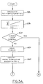
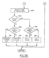
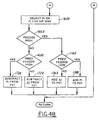
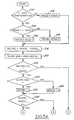
- Figures 2, 3A-3B, 4A-4B, 5A-5B, 6A6B and 7A-7B are high level flow charts of various operations performed by a portion of the embodiment shown in Figure 1.
-
-
Controller 10 is shown including a conventional microcomputer including: microprocessor unit 12; input ports 14;output ports 16; read onlymemory 18, for storing the controlled program;random access memory 20, for temporary data storage which may also be used for counters or timers; keepalive memory 22, for storing learned values; and a conventional data bus. Outputs are shown coupled to conventionalelectronic drivers 18. -
Controller 10 is shown receiving various signals from sensors coupled to engine 28 including: measurement of inducted mass air flow (MAF) fromair flow sensor 32, engine coolant temperature (T) fromtemperature sensor 40; and indication of engine speed (RPM) fromtachometer 42. - Output signal FEGO1 is provided from conventional exhaust
gas oxygen sensor 44 coupled to righthand exhaust manifold 56 which, in this particular example, is coupled to the right hand cylinder bank of a V-8 engine. Similarly, output signal FEGO2 is shown provided by conventional exhaustgas oxygen sensor 55 coupled to lefthand exhaust manifold 57. Both signal FEGO1 and signal FEGO2 are compared to a respective reference value selected at the midpoint of the sensor's average peak-to-peak output inrespective comparators 48 and 49. Respective signals FEGO1S and FEGO2S are thereby generated. Both signal FEGO1S and signal FEGO2S are two-state signals having a predetermined high voltage when exhaust gases are rich of stoichiometry and a predetermined low voltage when exhaust gases are lean of stoichiometry. - Another conventional exhaust
gas oxygen sensor 52 is shown coupled to the engine exhaust downstream of catalytic converter 50,sensor 52 provides signal REGO to controller 10 which is related to oxygen content in the exhaust gases. Output signal REGO is also compared to a reference value associated with its midpoint to provide two-state output signal REGOS to controller 10. Signal REGOS is a preselected high voltage when exhaust gas downstream of catalytic converter 50 are rich of stoichiometry and a low selected voltage when such exhaust gases are lean of stoichiometry. -
Intake manifold 58 andintake manifold 59 are respectively coupled to the right hand cylinder bank and left hand cylinder bank of engine 28 and are also shown communicating withrespective throttle body 60 andthrottle body 61. Each throttle body in turn is shown connected tosingle air intake 64.Throttle plate 62 and massair flow sensor 32 are shown coupled toair intake 64. - Continuing with Figure 1, conventional
electronic fuel injectors respective throttle body 60 andthrottle body 61.Fuel injectors 76 delivers fuel in response in proportion to the pulse width of signal fpwl fromcontroller 10 via one of the conventionalelectronic drivers 18. Similarly,fuel injector 77 delivers fuel in proportion to the pulse width of signal fpw2 fromcontroller 10 via one of theelectronic drivers 18. Fuel is delivered tofuel injectors fuel tank 80,fuel pump 82, andfuel rail 84. - Those skilled in the art will recognise that although a central fuel injected (CFI) system is shown for each cylinder bank, the invention claimed herein is also applicable to cylinder banks having a separate fuel injector for each cylinder.
- Referring now to Figure 2, a flow chart of a routine performed by
controller 10 to generate fuel trim signal FT is now described. The routine is entered after closed loop air/fuel control is commenced (step 104) in response to preselected engine operating conditions such as temperature. When closed loop control commences, signal REGOS is read from comparator 54 (step 108) and subsequently processed in the proportional plus integral control described below. - When signal REGOS is low (step 116), but was high during the previous background loop of controller 10 (step 118), preselected proportional term Pj is subtracted from fuel trim signal FT (step 120). When signal REGOS is low (step 116), and was also low during the previous background loop (step 118), preselected integral term Dj, is subtracted from fuel trim signal FT (step 122).
- Similarly, when signal REGOS is high (step 116), and was also high during the previous background loop of controller 10 (step 124), integral term Ai, is added to fuel trim signal FT (step 126). When signal REGOS is high, (step 116), but was low during the previous background loop (step 124), proportional term Pi is added to fuel trim signal FT (step 128).
- In accordance with the above described operation, fuel trim signal FT is generated from a proportional plus integral controller responsive to exhaust
gas oxygen sensor 52. The integration steps for integrating signal REGOS in a direction to cause a lean air/fuel correction are provided by integration steps Di, and the proportional term for such correction provided by Pi. Summarily, integral term Dj and proportional term Pj cause rich air/fuel corrections. - A separate fuel delivering and fuel adjusting routine is executed by
controller 10 for both the left hand cylinder bank and the right hand cylinder bank. Referring first to the right hand cylinder bank and corresponding Figures 3A-3B, an open loop fuel quantity is first determined by dividing the measurement of inducted mass air flow (MAF) by desired air/fuel ratio AFd which is typically the stoichiometric value for gasoline combustion (step 158r). This open loop fuel charge is then adjusted, in this example divided, by feedback variable FV1. The resulting desired quantity of fuel, expressed as signal Fd1, is then converted into corresponding pulse width signal fpw1 (step 159r). - After determining that closed loop control is desired (
step 160r), by monitoring engine operating conditions such as temperature (T), signal FEGO1S is read duringstep 162r. Duringstep 164r, fuel trim signal FT is transferred from the routine previously described with reference to Figure 2. - A conventional proportional plus integral feedback control routine is now executed during steps 165r-178r. Proportional term Pi or proportional term Pj are selected for achieving the desired air/fuel biasing indicated by fuel trim signal FT (step 165r). For example, in the event a lean air/fuel bias is required, proportional term Pi is increased. Conversely, if a rich air/fuel bias is required, proportional term Pj is increased in proportion to fuel trim signal FT. Those skilled in the art will recognise that air fuel biases may also be achieved by decreasing the proportional terms, increasing the integral terms, or decreasing the integral terms by an amount necessary to achieve the air/fuel bias.
- When signal FEGO1S is low (
step 166r), but was high during the previous background loop of controller 10 (step 168r), preselected proportional term Pj is subtracted from feedback variable FV1 (step 170r). When signal FEGO1S is low, (step 166r), and was also low during the previous background loop (step 168r), preselected integral term Δi is subtracted from feedback variable FV1 (step 172r). - Integral term Dj is added to feedback variable FV1 (
step 176r), when signal FEGO1S is high (step 166r), and was also high during the previous background loop of controller 10 (step 174r). When signal FEGO1S is high (step 166r), but was low during the previous background loop (step 174r), proportional term Pi is added to feedback variable FV1 (step 178r). - In accordance with the above-described operation, feedback variable FV1 is generated from the proportional plus integral controller (PI) responsive to two-state signal FEGO1S derived from upstream exhaust
gas oxygen sensor 44. - Substantially similar operations are performed by
controller 10 to: generate the desired quantity of liquid fuel delivered to engine 28 (fuel signal Fd2 and pulse width signal fpw2); and trim the desired fuel quantity by feedback variable FV2 which is related to both two-state signal FEGOIS and fuel trim signal FT. The routines executed bycontroller 10 for delivering fuel to leftintake manifold 59 is described in process steps 158L-178L shown in Figures 4A-4B. These process steps are substantially the same as those previously described with respect to delivering fuel to righthand intake manifold 58 with particular reference to Figures 3A-3B wherein like numerals refer to like process steps and like components. - Referring now to Figures 5A-5B, the routine for indicating transitions in the output of the upstream exhaust gas oxygen sensors are now provided. In this particular example in which a Y-pipe exhaust manifold is coupled to a single catalytic converter, and inferred upstream signal is generated (FEGOI). Inferred upstream signal FEGOI corresponds to a hypothetical single exhaust gas oxygen sensor positioned upstream of converter 50. The routine described herein is also applicable to a single exhaust gas oxygen sensor positioned upstream of converter 50.
- Referring to the particular subroutine shown in Figures 5A-5B, inferred signal FEGOI is set equal to output voltage amplitude FEGO1 from sensor 44 (step 214), when signal FEGO1 is greater than signal FEGO2 (step 204) and a Y-pipe exhaust manifold configuration is utilised (step 200). In the event output voltage FEGO2 from
sensor 55 is greater than output voltage FEGOI (step 204), inferred signal FEGO1 is set equal to output voltage FEGO2 (step 210). In the event a Y-pipe exhaust manifold configuration is not used (step 200), inferred signal FEGOI is set equal to the output voltage of the single exhaust gas oxygen sensor (sensor 44 in this particular example) as shown instep 214. - During
step 216, the difference between inferred signal FEGOIi during the present background loop (i) ofcontroller 10 and inferred signal FEGOIi-1 from the previous background loop (i-1) is taken to generate signal DELTAIi. The sign of signal DELTAIi is stored as signal SLOPESGN duringstep 220. When the absolute value of signal DELTAIi is less than deadband value DBAND (224), inferred signal FEGOIi-1 from the preceding background loop continues to be stored as signal FEGOIi for this background loop (step 226) and the subroutine exited duringstep 220. - If the absolute value of signal DELTAIi is greater than deadband value DBAND (224) and the slope of signal DELTAIi is positive (228), signal SLOPE is set equal to "1" (232). Signal SLOPE is set equal to "0" (234) when the slope of signal DELTAIi is negative (228) and the absolute value of signal DELTAIi is less than deadband value DBAND (224).
- When the slope of signal DELTAIi changes sign between two successive background loops of controller 10 (238), inferred signal FEGOIi is stored as a peak value (signal PEAK) during the present background loop (i) as shown in
step 242. - When the difference between present signal PEAK and previously stored peak value (signal PRVPEAK) exceeds calibratable value CATAMPU (246), transition flag TRANSFEGOI for inferred signal FEGOI is set during
step 250 and this routine exited. - The subroutine for detecting transitions in the output amplitude of signal REGO from sensor-52 is now described with reference to the subroutine shown in Figures 6A-6B.
- The output amplitude of signal REGO is read during
step 314. During step 316, the difference between signal REGOi during the present background loop (i) ofcontroller 10 and signal REGOi-1 from the previous background loop (i-1) is taken to generate signal DELTARi. The sign of signal DELTARi is stored as signal SLOPESGN duringstep 320. When the absolute value of signal DELTARi is less than deadband value DBAND (323), signal REGOi-1 from the preceding background loop continues to be stored as signal REGOi for this background loop (step 326) and the subroutine exited duringstep 320. - If the absolute value of signal DELTARi is greater than deadband value DBAND (324) and the slope of signal DELTARi is positive (328), signal SLOPE is set equal to "1" (332). Signal SLOPE is set equal to "0" (334) when the slope of signal DELTARi is negative (328) and the absolute value of signal DELTARi is less than deadband value DBAND (324).
- When the slope of signal DELTARi changes sign between two successive background loops of controller 10 (338), signal REGOi is stored as a peak value (signal PEAK) during the present background loop (i) as shown in
step 342. - When the difference between present signal PEAK and previously stored peak value (signal PRVPEAK) exceeds calibratable value CATAMPU (346), transition flag TRANSREGO for signal REGO is set during
step 350 and this routine exited. - An example of indicating converter efficiency is now described with particular reference to the flow charts shown in Figures 7A-7B. During
step 690, initial engine conditions are checked before entering the test cycle described below. More specifically, engine temperature (T) should be within a predetermined range, a predetermined time should have elapsed since the engine was started, and closed loop air/fuel control should have been operable for at least a preselected time. - For each background loop, inferred signal FEGOI is read (step 594) from the subroutine previously described with reference to Figures 5A-5B. Inferred signal FEGOI is an inference of an output from a hypothetical exhaust gas oxygen sensor exposed to a hypothetical blended mixture of exhaust gases from right
hand exhaust manifold 56 and lefthand exhaust manifold 57. - Continuing with Figures 7A-7B, the inducted air flow range in which engine 28 is operating is determined during
steps - When engine operation is within air flow range (2) as shown in
step 704, count CIE2 and count CR2 are determined insteps steps - The above described operation occurs for each air flow range comprising the test period. When engine 28 is operating within the highest air flow range (n) for the test period, as shown in
step 706, subtest period (n), count CIEn, and count CRn are generated as shown instep - During
step 750, a determination is made as to whether engine 28 has operated in all air flow ranges (1 · · · n) for respective subtest periods (1 · · · n) of the converter test period. Stated another way,step 750 determines when each count of transitions in signal IE (CIE1 · · · CIEn) have reached their respective maximum values (CIE1max · · · CIEnmax). Each count of transitions in signal IE (CIE1 · · · CIEn) for respective test periods (1 · · · n) are summed instep 754 to generate total count CIEt. For reasons described above, the same total count CIEt may be obtained by summing each maximum count (CIE1max · · · CIEnmax) for respective test periods (1 · · · n). - Total count CRt is generated in step 756 by summing each count (CR1 · · · CRn) for respective test periods (1 · · · n). A Ratio of total counts CRt to total count CIEt is then calculated during step 760 and all counts subsequently reset in
step 762. If the calculated ratio is greater than a preselected reference ratio (RATf), a flag is set (steps 766 and 770) indicating that converter efficiency is below a preselected limit. - The actual ratio calculated from
step 766 may be used to provide a measurement of converter efficiency. Due to the advantages described previously herein, this indication of converter efficiency is accurate over a wider range of converter efficiencies than heretofore possible. - An example of operation has been presented wherein both
upstream sensors
Claims (15)
- A control method for an engine having its exhaust (56,57) coupled to a catalytic converter (50), comprising the steps of:detecting changes in gradient of output amplitude from a downstream exhaust gas oxygen sensor (52) positioned downstream of the converter (50);providing a downstream switch indication whenever a difference between a first of said downstream sensor (52) output amplitudes occurring at a first of said gradient changes and a subsequent second of said downstream sensor output amplitudes occurring at a second of said gradient changes exceeds a predetermined value; andindicating catalytic efficiency from a ratio of counts of said downstream switch indications to a ratio of counts in transitions of an upstream signal derived from at least one upstream exhaust gas oxygen sensor (44,55) positioned upstream of the converter.
- A control method as claimed in claim 1 further comprising the steps of: generating a downstream two-state signal by comparing a reference value to downstream sensor output amplitude; and adjusting fuel delivered to the engine with a correction signal derived from said downstream two-state signal;
- A control method as claimed in Claim 2 further comprising the steps of: generating an upstream two-state signal by comparing a reference amplitude to output amplitude of said upstream exhaust gas oxygen sensor; and further correcting said delivered fuel by a feedback variable derived from said upstream two-state signal.
- A control method as claimed in Claim 3, wherein said upstream signal is said upstream sensor output amplitude.
- A method as claimed in Claim 4, wherein said correction signal adjusts said fuel delivered by biasing said feedback variable.
- A control method as claimed in Claim 4, wherein said upstream transitions are generated whenever a difference between a first of said upstream sensor output amplitudes occurring at a first of said gradient changes and a subsequent second of said downstream sensor output amplitudes occurring at a second changes in gradient of said upstream sensor output amplitudes exceeds a preselected difference.
- A control method as claimed in Claim 2, wherein said upstream signal is inferred from the output of a first upstream exhaust gas oxygen sensor and a second upstream exhaust gas oxygen sensor, both being positioned upstream of the converter.
- A control method as claimed in Claim 7, wherein said upstream signal is set equal to said first sensor output when said first sensor output is greater than said second sensor output and is set equal to said second sensor output when said second sensor output is greater than said first sensor output.
- A control method for an engine having its exhaust coupled to a catalytic converter, comprising the steps of:delivering fuel to the engine in proportion to a fuel signal;adjusting said fuel signal with a feedback variable derived from a comparison of a reference amplitude to output amplitude of an upstream exhaust gas oxygen sensor positioned upstream of the converter;biasing said fuel signal in relation to a biasing signal derived from a comparison of a reference value to an output amplitude of a downstream exhaust gas oxygen sensor positioned downstream of the converter;generating a difference in amplitude of said downstream sensor output amplitude each sample period;storing downstream sensor output amplitude as a peak amplitude each sample period when said downstream sensor amplitude difference changes signs;indicating a downstream sensor transition when said downstream sensor difference changes signs and a difference between said stored peak value and said stored peak value stored during a previous change in said sign of said downstream sensor amplitude exceeds a predetermined value; andindicating converter efficiency from a ratio of transitions of said downstream sensor transitions to transitions of an upstream signal derived from said upstream sensor output amplitude.
- A control method as claimed in claim 9 further comprising the steps of adjusting said predetermined value in relation to an average of said difference between stored peak values.
- A control method as claimed in Claim 9 further comprising the steps of:generating a difference in amplitude of said upstream signal each sample period;storing said upstream signal as a peak amplitude each sample period when said upstream signal amplitude difference changes sign; andindicating an upstream signal transition when said upstream signal difference changes sign and a difference between said stored peak value and said stored peak value stored during a previous change in said sign of said upstream signal exceeds a preselected value.
- A control method as claimed in Claim 9, wherein said upstream signal is inferred from both said upstream sensor output and from a second exhaust gas oxygen sensor positioned upstream of the converter.
- A control method as claimed in Claim 9, wherein said upstream signal is equal to said upstream sensor output amplitude.
- A control system for an engine having its exhaust coupled to a catalytic converter, comprising:a fuel controller generating a downstream two-state signal by comparing a reference value to a downstream exhaust gas oxygen sensor positioned downstream of the converter and adjusting fuel delivered to the engine with a correction signal derived from said downstream two-state signal;processing means for detecting changes in gradient of said downstream sensor output amplitude , said processing means providing a downstream switch indication whenever a difference between a first of said downstream sensor output amplitudes occurring at a first of said gradient changes and a subsequent second of said downstream sensor output amplitudes occurring at a second of said gradient changes exceeds a predetermined value; andindicating means for indicating catalytic efficiency from a ratio of counts of said downstream switch indications to a ratio of counts in transitions of an upstream signal derived from at least one upstream exhaust gas oxygen sensor positioned upstream of the converter.
- A control system as claimed in claim 14, wherein said fuel controller further adjust said delivered fuel in response to a feedback variable derived from said upstream sensor.
Applications Claiming Priority (2)
| Application Number | Priority Date | Filing Date | Title |
|---|---|---|---|
| US414569 | 1982-09-02 | ||
| US08/414,569 US5544481A (en) | 1995-03-31 | 1995-03-31 | Engine air/fuel control system and catalytic converter monitoring |
Publications (3)
| Publication Number | Publication Date |
|---|---|
| EP0735259A2 EP0735259A2 (en) | 1996-10-02 |
| EP0735259A3 EP0735259A3 (en) | 1997-05-28 |
| EP0735259B1 true EP0735259B1 (en) | 2000-06-07 |
Family
ID=23642020
Family Applications (1)
| Application Number | Title | Priority Date | Filing Date |
|---|---|---|---|
| EP96301409A Expired - Lifetime EP0735259B1 (en) | 1995-03-31 | 1996-03-01 | Engine air/fuel control system |
Country Status (4)
| Country | Link |
|---|---|
| US (1) | US5544481A (en) |
| EP (1) | EP0735259B1 (en) |
| JP (1) | JPH08277738A (en) |
| DE (1) | DE69608731T2 (en) |
Families Citing this family (18)
| Publication number | Priority date | Publication date | Assignee | Title |
|---|---|---|---|---|
| SE505235C2 (en) * | 1995-06-07 | 1997-07-21 | Volvo Ab | Method and apparatus for determining the oxygen buffer capacity of a catalytic exhaust cleaner |
| US5845489A (en) * | 1995-11-08 | 1998-12-08 | Denso Corporation | Abnormality detector for air-fuel ratio control system |
| US5598703A (en) * | 1995-11-17 | 1997-02-04 | Ford Motor Company | Air/fuel control system for an internal combustion engine |
| US5653104A (en) * | 1995-11-17 | 1997-08-05 | Ford Global Technologies, Inc. | Engine air/fuel control system with adaptively alignment of a catalytic converter's peak efficiency window |
| US5758494A (en) * | 1997-01-16 | 1998-06-02 | Ford Global Technologies, Inc. | System and method for adaptive switch determination of exhaust gas sensors |
| US5974786A (en) * | 1997-01-21 | 1999-11-02 | Ford Global Technologies, Inc. | Adaptive time window to synchronize pre- and post-catalyst oxygen sensor switch counters |
| US5848528A (en) * | 1997-08-13 | 1998-12-15 | Siemens Automotive Corporation | Optimization of closed-loop and post O2 fuel control by measuring catalyst oxygen storage capacity |
| US5894727A (en) * | 1997-11-03 | 1999-04-20 | Ford Global Technologies, Inc. | Method and system for generating an inferred EGO signal in an asymmetrical Y-pipe exhaust system |
| US5974790A (en) * | 1998-03-05 | 1999-11-02 | Ford Global Technologies, Inc. | Catalytic converter decontamination method |
| US6151889A (en) * | 1998-10-19 | 2000-11-28 | Ford Global Technologies, Inc. | Catalytic monitoring method |
| DE19852294A1 (en) | 1998-11-12 | 2000-05-18 | Bayerische Motoren Werke Ag | Exhaust system of a multi-cylinder internal combustion engine |
| US6523341B1 (en) | 2000-01-07 | 2003-02-25 | Ford Global Technologies, Inc. | Cold start vehicle catalyst monitor |
| US6354077B1 (en) * | 2000-01-20 | 2002-03-12 | Ford Global Technologies, Inc. | Method and system for controlling air/fuel level in two-bank exhaust system |
| US6668617B2 (en) * | 2001-08-01 | 2003-12-30 | Daimlerchrysler Corporation | 02 Sensor filter |
| US6532734B1 (en) | 2002-02-01 | 2003-03-18 | Ford Global Technologies, Inc. | On-board diagnostic catalyst monitoring system |
| US6804951B2 (en) | 2002-11-06 | 2004-10-19 | Ford Global Technologies, Llc | On-board diagnostic catalyst monitoring system |
| DE102004015836A1 (en) * | 2004-03-31 | 2005-11-03 | Siemens Ag | Method and device for controlling an internal combustion engine |
| JP7474207B2 (en) * | 2021-02-10 | 2024-04-24 | 日立Astemo株式会社 | Air-fuel ratio control device |
Family Cites Families (11)
| Publication number | Priority date | Publication date | Assignee | Title |
|---|---|---|---|---|
| GB9003235D0 (en) * | 1990-02-13 | 1990-04-11 | Lucas Ind Plc | Exhaust gas catalyst monitoring |
| JP2960576B2 (en) * | 1991-06-28 | 1999-10-06 | マツダ株式会社 | Engine exhaust purification device |
| JPH05280402A (en) * | 1992-03-30 | 1993-10-26 | Fuji Heavy Ind Ltd | Deterioration detecting method for engine catalyzer |
| JPH06101455A (en) * | 1992-09-18 | 1994-04-12 | Honda Motor Co Ltd | Device for detecting catalyst deterioration of internal combustion engine |
| US5272872A (en) * | 1992-11-25 | 1993-12-28 | Ford Motor Company | Method and apparatus of on-board catalytic converter efficiency monitoring |
| US5289678A (en) * | 1992-11-25 | 1994-03-01 | Ford Motor Company | Apparatus and method of on-board catalytic converter efficiency monitoring |
| US5357751A (en) * | 1993-04-08 | 1994-10-25 | Ford Motor Company | Air/fuel control system providing catalytic monitoring |
| US5386693A (en) * | 1993-09-27 | 1995-02-07 | Ford Motor Company | Engine air/fuel control system with catalytic converter monitoring |
| US5383333A (en) * | 1993-10-06 | 1995-01-24 | Ford Motor Company | Method for biasing a hego sensor in a feedback control system |
| US5385016A (en) * | 1993-12-27 | 1995-01-31 | Ford Motor Company | Air/fuel control system responsive to duo upstream EGO sensors with converter monitoring |
| US5396875A (en) * | 1994-02-08 | 1995-03-14 | Ford Motor Company | Air/fuel control with adaptively learned reference |
-
1995
- 1995-03-31 US US08/414,569 patent/US5544481A/en not_active Expired - Fee Related
-
1996
- 1996-01-30 JP JP8014541A patent/JPH08277738A/en active Pending
- 1996-03-01 EP EP96301409A patent/EP0735259B1/en not_active Expired - Lifetime
- 1996-03-01 DE DE69608731T patent/DE69608731T2/en not_active Expired - Fee Related
Also Published As
| Publication number | Publication date |
|---|---|
| DE69608731T2 (en) | 2000-10-05 |
| US5544481A (en) | 1996-08-13 |
| EP0735259A2 (en) | 1996-10-02 |
| DE69608731D1 (en) | 2000-07-13 |
| JPH08277738A (en) | 1996-10-22 |
| EP0735259A3 (en) | 1997-05-28 |
Similar Documents
| Publication | Publication Date | Title |
|---|---|---|
| US5544481A (en) | Engine air/fuel control system and catalytic converter monitoring | |
| US4434768A (en) | Air-fuel ratio control for internal combustion engine | |
| US4676215A (en) | Method and apparatus for controlling the operating characteristic quantities of an internal combustion engine | |
| US4508075A (en) | Method and apparatus for controlling internal combustion engines | |
| US4646697A (en) | Method and apparatus for controlling the operating characteristic quantities of an internal combustion engine | |
| US4671107A (en) | EGR diagnostic system | |
| US5157920A (en) | Method of and an apparatus for controlling the air-fuel ratio of an internal combustion engine | |
| US4442812A (en) | Method and apparatus for controlling internal combustion engines | |
| US5168700A (en) | Method of and an apparatus for controlling the air-fuel ratio of an internal combustion engine | |
| US5927260A (en) | Device for diagnosing oxygen sensor deterioration | |
| US4467770A (en) | Method and apparatus for controlling the air-fuel ratio in an internal combustion engine | |
| US4674459A (en) | Apparatus for metering an air-fuel mixture to an internal combustion engine | |
| US5385016A (en) | Air/fuel control system responsive to duo upstream EGO sensors with converter monitoring | |
| US5638800A (en) | Method and apparatus for controlling air-fuel ratio learning of an internal combustion engine | |
| JPS6165038A (en) | Air-fuel ratio control system | |
| US5251437A (en) | Method and system for controlling air/fuel ratio for internal combustion engine | |
| US5404718A (en) | Engine control system | |
| US5033440A (en) | Apparatus for controlling air/fuel ratio of internal combustion engine | |
| US5749222A (en) | Catalyst soundness assessment device | |
| US4357828A (en) | Method of indicating a basic air-fuel ratio condition of an internal combustion engine | |
| US5386693A (en) | Engine air/fuel control system with catalytic converter monitoring | |
| JPS62210229A (en) | Mixed fuel injection method | |
| US4616618A (en) | Apparatus for metering an air-fuel mixture to an internal combustion engine | |
| US5381656A (en) | Engine air/fuel control system with catalytic converter monitoring | |
| US4462374A (en) | Air-fuel ratio control method and apparatus utilizing an exhaust gas concentration sensor |
Legal Events
| Date | Code | Title | Description |
|---|---|---|---|
| PUAI | Public reference made under article 153(3) epc to a published international application that has entered the european phase |
Free format text: ORIGINAL CODE: 0009012 |
|
| AK | Designated contracting states |
Kind code of ref document: A2 Designated state(s): DE FR GB |
|
| PUAL | Search report despatched |
Free format text: ORIGINAL CODE: 0009013 |
|
| AK | Designated contracting states |
Kind code of ref document: A3 Designated state(s): DE FR GB |
|
| 17P | Request for examination filed |
Effective date: 19971020 |
|
| GRAG | Despatch of communication of intention to grant |
Free format text: ORIGINAL CODE: EPIDOS AGRA |
|
| 17Q | First examination report despatched |
Effective date: 19990407 |
|
| GRAG | Despatch of communication of intention to grant |
Free format text: ORIGINAL CODE: EPIDOS AGRA |
|
| GRAG | Despatch of communication of intention to grant |
Free format text: ORIGINAL CODE: EPIDOS AGRA |
|
| GRAH | Despatch of communication of intention to grant a patent |
Free format text: ORIGINAL CODE: EPIDOS IGRA |
|
| GRAH | Despatch of communication of intention to grant a patent |
Free format text: ORIGINAL CODE: EPIDOS IGRA |
|
| GRAA | (expected) grant |
Free format text: ORIGINAL CODE: 0009210 |
|
| AK | Designated contracting states |
Kind code of ref document: B1 Designated state(s): DE FR GB |
|
| PG25 | Lapsed in a contracting state [announced via postgrant information from national office to epo] |
Ref country code: FR Free format text: LAPSE BECAUSE OF FAILURE TO SUBMIT A TRANSLATION OF THE DESCRIPTION OR TO PAY THE FEE WITHIN THE PRESCRIBED TIME-LIMIT Effective date: 20000607 |
|
| REF | Corresponds to: |
Ref document number: 69608731 Country of ref document: DE Date of ref document: 20000713 |
|
| EN | Fr: translation not filed | ||
| PLBE | No opposition filed within time limit |
Free format text: ORIGINAL CODE: 0009261 |
|
| STAA | Information on the status of an ep patent application or granted ep patent |
Free format text: STATUS: NO OPPOSITION FILED WITHIN TIME LIMIT |
|
| 26N | No opposition filed | ||
| REG | Reference to a national code |
Ref country code: GB Ref legal event code: IF02 |
|
| PGFP | Annual fee paid to national office [announced via postgrant information from national office to epo] |
Ref country code: GB Payment date: 20040205 Year of fee payment: 9 |
|
| PGFP | Annual fee paid to national office [announced via postgrant information from national office to epo] |
Ref country code: DE Payment date: 20040331 Year of fee payment: 9 |
|
| PG25 | Lapsed in a contracting state [announced via postgrant information from national office to epo] |
Ref country code: GB Free format text: LAPSE BECAUSE OF NON-PAYMENT OF DUE FEES Effective date: 20050301 |
|
| PG25 | Lapsed in a contracting state [announced via postgrant information from national office to epo] |
Ref country code: DE Free format text: LAPSE BECAUSE OF NON-PAYMENT OF DUE FEES Effective date: 20051001 |
|
| GBPC | Gb: european patent ceased through non-payment of renewal fee |
Effective date: 20050301 |