EP0733760A2 - A device for opening the tailgate of motor vehicles, particularly motor cars - Google Patents
A device for opening the tailgate of motor vehicles, particularly motor cars Download PDFInfo
- Publication number
- EP0733760A2 EP0733760A2 EP96200730A EP96200730A EP0733760A2 EP 0733760 A2 EP0733760 A2 EP 0733760A2 EP 96200730 A EP96200730 A EP 96200730A EP 96200730 A EP96200730 A EP 96200730A EP 0733760 A2 EP0733760 A2 EP 0733760A2
- Authority
- EP
- European Patent Office
- Prior art keywords
- tailgate
- latch
- roller
- unlocking
- pedal
- Prior art date
- Legal status (The legal status is an assumption and is not a legal conclusion. Google has not performed a legal analysis and makes no representation as to the accuracy of the status listed.)
- Withdrawn
Links
Images


Classifications
-
- E—FIXED CONSTRUCTIONS
- E05—LOCKS; KEYS; WINDOW OR DOOR FITTINGS; SAFES
- E05B—LOCKS; ACCESSORIES THEREFOR; HANDCUFFS
- E05B17/00—Accessories in connection with locks
- E05B17/0025—Devices for forcing the wing firmly against its seat or to initiate the opening of the wing
- E05B17/0033—Devices for forcing the wing firmly against its seat or to initiate the opening of the wing for opening only
-
- E—FIXED CONSTRUCTIONS
- E05—LOCKS; KEYS; WINDOW OR DOOR FITTINGS; SAFES
- E05B—LOCKS; ACCESSORIES THEREFOR; HANDCUFFS
- E05B83/00—Vehicle locks specially adapted for particular types of wing or vehicle
- E05B83/16—Locks for luggage compartments, car boot lids or car bonnets
-
- E—FIXED CONSTRUCTIONS
- E05—LOCKS; KEYS; WINDOW OR DOOR FITTINGS; SAFES
- E05B—LOCKS; ACCESSORIES THEREFOR; HANDCUFFS
- E05B53/00—Operation or control of locks by mechanical transmissions, e.g. from a distance
- E05B53/001—Foot-operation
Definitions
- the present invention relates to a device for opening the tailgate of motor vehicles, in particular motor cars.
- tailgates of motor vehicles in particular motor cars, have systems for locking/unlocking the tailgate with respect to the motor vehicle body.
- Such systems include latch or catch members which interengage with each other and/or with retaining members, usually a cylindrical pin fixed, for example, to the vehicle body, and held in a closed position by resilient means, typically springs.
- a push button provided with a keyhole, located on the lock or close to it, allows the latch member to be disengaged by acting on the resilient means.
- a security device is usually provided to prevent unauthorised persons (thieves) from releasing the latch members, the device being unlocked either by the aforesaid key or by means of an electrically activated servomechanism which can be controlled by a remote control using, for example, infra red radiation.
- the push button of the lock must then be pressed to open the tailgate, as already stated, thereby freeing the jaws and allowing the tailgate to be lifted manually.
- the aim of the present invention is to provide a device which opens the tailgate to a point at which the air springs, with which tailgates are normally provided, cause it to open completely without the person opening the tailgate needing to use their hands when they are otherwise engaged.
- the invention achieves the aforesaid aim by means of a device for opening the tailgate of motor vehicles, in particular motor cars, having the characteristics specifically referred to in the following Claims.
- reference numeral 2 generally indicates the rear part of a motor car provided with a rear door or tailgate 4.
- the tailgate 4 has two air springs for lifting the tailgate 4, only one of which indicated 6 is visible in the drawing, a similar air spring being positioned symmetrically on the opposite side of the body 2.
- a pedal 8 operates the device which is the subject of the present invention, indicated II in Figure 1 and represented in detail on an enlarged scale in Figure 2.
- Reference numeral 10 indicates the keyplate of a lock 12, having a keyhole 14.
- a finger 16 projects from the keyplate 10 and contacts a plate or arm 18, the finger 16 being rotatable about an axis 20 substantially perpendicular to the body 22 of the motor vehicle.
- the lock 12 includes a first latch member 24 engaged in a seat 26 in a second latch member 28.
- a spring 30 holds the first latch member 24 against the second latch member 28 in a closed position. In this position, the second latch member 28 engages a pin 32 fixed to the body 22 of the motor vehicle.
- the first latch member 24 and the second latch member 28 are rotatable about axes fixed relative to the body 22 and substantially perpendicular thereto.
- a projection or wing 36 on the first latch member 24 contacts a finger 38 connected by a Bowden cable 40 to a third latch member 42 which cooperates with a fourth latch member 44 connected to the plate 18 by a Bowden cable 45.
- the third latch member 42 and the fourth latch member 44 are rotatably mounted on a plate 46 fixed to the body 22 and are held in a closed position by a spring 48.
- the third latch member 42 engages a pin or roller 50 fixed to a rod 52 which is movable vertically and carries the pedal 8.
- the pin 50 is fixed to a first end of a rod 54 which carries a push-rod 56 at its second end, this push-rod being in contact with the tailgate 4.
- the rod 54 is pivotably mounted on the body 22, its rotation being opposed by a spring 58.
- the plate 46 has a slot 60 in which the pin 50 is slidable.
- the device which is the subject of the invention functions as follows.
- Figure 2 illustrates a situation in which the device is locked and the pedal 8 cannot be operated.
- the Bowden cables can be replaced by lever mechanisms.
Landscapes
- Lock And Its Accessories (AREA)
Abstract
A device for opening the tailgate of a motor vehicle includes a pedal device (8) which controls a lever mechanism (52, 54, 56) for lifting the tailgate. The pedal device (8) is normally in a locked position and can be operated only after the actuation of the security device (16) of the lock (10) which locks the tailgate to the body (22). <IMAGE>
Description
- The present invention relates to a device for opening the tailgate of motor vehicles, in particular motor cars.
- As is known, tailgates of motor vehicles, in particular motor cars, have systems for locking/unlocking the tailgate with respect to the motor vehicle body. Such systems (locks) include latch or catch members which interengage with each other and/or with retaining members, usually a cylindrical pin fixed, for example, to the vehicle body, and held in a closed position by resilient means, typically springs.
- A push button provided with a keyhole, located on the lock or close to it, allows the latch member to be disengaged by acting on the resilient means.
- A security device is usually provided to prevent unauthorised persons (thieves) from releasing the latch members, the device being unlocked either by the aforesaid key or by means of an electrically activated servomechanism which can be controlled by a remote control using, for example, infra red radiation.
- Once the security device has been unlocked, the push button of the lock must then be pressed to open the tailgate, as already stated, thereby freeing the jaws and allowing the tailgate to be lifted manually.
- The above is easy when the tailgate can be opened with free hands but, in the not infrequent situation that one is holding parcels, bags and even, if it is raining, an umbrella all at the same time, opening the tailgate can be anything but easy.
- The aim of the present invention is to provide a device which opens the tailgate to a point at which the air springs, with which tailgates are normally provided, cause it to open completely without the person opening the tailgate needing to use their hands when they are otherwise engaged.
- The invention achieves the aforesaid aim by means of a device for opening the tailgate of motor vehicles, in particular motor cars, having the characteristics specifically referred to in the following Claims.
- Further characteristics and advantages of the present invention will become evident in the course of the following detailed description, given purely by way of non-limitative example with reference to the accompanying drawings, in which:
- Figure 1 is a partially cut-away, schematic perspective view of the rear part of the body of a motor car provided with the device according to the invention;
- Figure 2 is an enlarged, interrupted elevational view of a detail indicated II in Figure 1; and
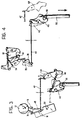
- Figures 3 and 4 illustrate the positions of parts shown in Figure 2 during the operation of the device according to the invention.
- With reference to Figures 1 to 4,
reference numeral 2 generally indicates the rear part of a motor car provided with a rear door or tailgate 4. - The tailgate 4 has two air springs for lifting the tailgate 4, only one of which indicated 6 is visible in the drawing, a similar air spring being positioned symmetrically on the opposite side of the
body 2. - A
pedal 8 operates the device which is the subject of the present invention, indicated II in Figure 1 and represented in detail on an enlarged scale in Figure 2. -
Reference numeral 10 indicates the keyplate of alock 12, having a keyhole 14. Afinger 16 projects from thekeyplate 10 and contacts a plate orarm 18, thefinger 16 being rotatable about anaxis 20 substantially perpendicular to thebody 22 of the motor vehicle. - The
lock 12 includes afirst latch member 24 engaged in a seat 26 in asecond latch member 28. A spring 30 holds the firstlatch member 24 against thesecond latch member 28 in a closed position. In this position, thesecond latch member 28 engages apin 32 fixed to thebody 22 of the motor vehicle. - The
first latch member 24 and thesecond latch member 28 are rotatable about axes fixed relative to thebody 22 and substantially perpendicular thereto. - A projection or wing 36 on the
first latch member 24 contacts afinger 38 connected by a Bowdencable 40 to athird latch member 42 which cooperates with afourth latch member 44 connected to theplate 18 by a Bowdencable 45. - The
third latch member 42 and thefourth latch member 44 are rotatably mounted on aplate 46 fixed to thebody 22 and are held in a closed position by aspring 48. Thethird latch member 42 engages a pin orroller 50 fixed to arod 52 which is movable vertically and carries thepedal 8. - The
pin 50 is fixed to a first end of arod 54 which carries a push-rod 56 at its second end, this push-rod being in contact with the tailgate 4. Therod 54 is pivotably mounted on thebody 22, its rotation being opposed by aspring 58. Theplate 46 has aslot 60 in which thepin 50 is slidable. - The device which is the subject of the invention functions as follows.
- Figure 2 illustrates a situation in which the device is locked and the
pedal 8 cannot be operated. - Action on the
keyplate 10 with the key or a servomechanism, not illustrated, in the sense indicated by the arrow (see Figure 3), rotates theplate 18 about its axis ofrotation 20. Through the Bowdencable 45, this rotation causes thefourth latch member 44 to overcome the resistance of thespring 48 and rotate from the position illustrated in broken outline in Figure 3 to that illustrated in full outline, thereby freeing itself from engagement with thethird latch member 42 which rotates in the sense indicated by the arrow in Figure 3, simultaneously freeing itself from thepin 50. - The rotation of the
third latch member 42 in the sense of the arrow is transmitted by the Bowdencable 40 to thefinger 38 which moves from the position illustrated in broken outline in Figure 4 to that illustrated in full outline, causing thefirst latch member 24 to rotate in the sense indicated by the arrow, with its consequent freeing from thesecond latch member 28 and the freeing of this latter from thepin 32. - In the situation described, the tailgate 4 (Figure 1) is released and, if the
pedal 8 is depressed from the outside so as to overcome the resistance of thespring 58, thelever 52 can slide downwards in the direction indicated by the arrow, pulling thepin 50 downwards (Figure 2). This movement causes thelever 54 to rotate about its centre of rotation with the consequent lifting of thepush rod 56 in the direction indicated by the arrow, thereby raising the tailgate until the air spring 6 and its homologue come into action and lift the tailgate 4 completely. - It will be clear from the above that a security device is provided for the operation of the
pedal 8, namely that thepedal 8 can be operated only when theplate 18 is released by means of a key or remote control. - Naturally, the principles of the invention remaining the same, the manufacturing details and the embodiments can be varied widely with respect to that which has been described and illustrated without leaving the scope of the present invention.
- In particular, the Bowden cables can be replaced by lever mechanisms.
Claims (15)
- A device for opening the tailgate (4) of a motor vehicle, in particular a motor car, comprising:- locking/unlocking means (24, 28, 30) for locking/unlocking the tailgate (4) with respect to the body (22) of the motor vehicle, the said locking/unlocking means (24, 28, 30) being constituted by cooperating first (24) and second (28) latch devices interconnected by resilient means (30), the second latch device (28) being engageable with a pin (32) in the locked state,- actuating means for unlocking the locking/unlocking means (24, 28, 30),- security means (16) for activating the actuating means, operable from the outside, characterised in that it further includes an auxiliary device (8, 52, 50, 54, 58, 56, 60, 46) enabled by the security means (16) for unlocking the locking/unlocking means (24, 28, 30) and partially raising the tailgate (4) of the motor vehicle.
- A device according to Claim 1, characterised in that the auxiliary device (8, 52, 50, 54, 58, 56, 60, 46) includes a pedal (8) which can be operated from outside the vehicle.
- A device according to Claim 2, characterised in that the pedal (8) has a substantially vertical portion (52) terminating in a roller (50).
- A device according to Claim 3, characterised in that the roller (50) is fixed to a lever (54) pivotally mounted on the body (22).
- A device according to Claim 4, characterised in that the roller (50) is slidable in a slot (60) formed in a plate (46) fixed to the body (22).
- A device according to Claim 4, characterised in that the lever (54) is associated with a spring (58) which opposes the action of the pedal (8).
- A device according to any one of claims 2 to 6, characterised in that the lever (54) opposite that which is connected to the roller (50) is fixed to a push rod (56) which bears against the tailgate (4) of the motor vehicle and is able to lift the tailgate (4) in the direction of opening on operation of the pedal (8).
- A device according to any one of the preceding claims, characterised in that the plate (46) carries secured thereto a security assembly (42, 44, 48) associated with the roller (50).
- A device according to Claim 8, characterised in that the security assembly (42, 44, 48) includes cooperating third (42) and fourth (44) latch devices held together by a resilient element (48).
- A device according to Claim 9, characterised in that the third latch device (42) includes a groove-like seat for the roller (50).
- A device according to any one of the preceding claims, characterised in that the fourth latch device (44) is connected to an arm (18) rotatably mounted on the body (22).
- A device according to any one of the preceding claims, characterised in that the arm (18) is rotatable under the action of the security means (16).
- A device according to any one of the preceding claims, characterised in that the third latch device (42) is connected to a finger (38) which cooperates with a wing (36) of the first latch device (24).
- A device according to any one of the preceding claims, characterised in that the fourth latch device (44) is connected to the arm (18) by a Bowden cable (45).
- A device according to any one of the preceding claims, characterised in that the third latch member device (42) is connected to the finger (38) by a Bowden cable (40).
Applications Claiming Priority (2)
| Application Number | Priority Date | Filing Date | Title |
|---|---|---|---|
| ITTO950221 | 1995-03-23 | ||
| IT95TO000221A IT1280819B1 (en) | 1995-03-23 | 1995-03-23 | DEVICE FOR OPENING THE REAR DOOR OF MOTOR VEHICLES, PARTICULARLY CARS. |
Publications (2)
| Publication Number | Publication Date |
|---|---|
| EP0733760A2 true EP0733760A2 (en) | 1996-09-25 |
| EP0733760A3 EP0733760A3 (en) | 1997-04-02 |
Family
ID=11413398
Family Applications (1)
| Application Number | Title | Priority Date | Filing Date |
|---|---|---|---|
| EP96200730A Withdrawn EP0733760A3 (en) | 1995-03-23 | 1996-03-16 | A device for opening the tailgate of motor vehicles, particularly motor cars |
Country Status (2)
| Country | Link |
|---|---|
| EP (1) | EP0733760A3 (en) |
| IT (1) | IT1280819B1 (en) |
Cited By (2)
| Publication number | Priority date | Publication date | Assignee | Title |
|---|---|---|---|---|
| WO2007054087A1 (en) * | 2005-11-08 | 2007-05-18 | Baby Dan A/S | A locking mechanism for a child safety barrier |
| EP2055875A1 (en) | 2007-11-02 | 2009-05-06 | GM Global Technology Operations, Inc. | Actuating arrangement |
Family Cites Families (1)
| Publication number | Priority date | Publication date | Assignee | Title |
|---|---|---|---|---|
| US4421350A (en) * | 1979-06-18 | 1983-12-20 | Toyo Kogyo Co., Ltd. | Foot-operated, latch releasing mechanism for automobile doors |
-
1995
- 1995-03-23 IT IT95TO000221A patent/IT1280819B1/en active IP Right Grant
-
1996
- 1996-03-16 EP EP96200730A patent/EP0733760A3/en not_active Withdrawn
Cited By (2)
| Publication number | Priority date | Publication date | Assignee | Title |
|---|---|---|---|---|
| WO2007054087A1 (en) * | 2005-11-08 | 2007-05-18 | Baby Dan A/S | A locking mechanism for a child safety barrier |
| EP2055875A1 (en) | 2007-11-02 | 2009-05-06 | GM Global Technology Operations, Inc. | Actuating arrangement |
Also Published As
| Publication number | Publication date |
|---|---|
| ITTO950221A1 (en) | 1996-09-23 |
| ITTO950221A0 (en) | 1995-03-23 |
| IT1280819B1 (en) | 1998-02-11 |
| EP0733760A3 (en) | 1997-04-02 |
Similar Documents
| Publication | Publication Date | Title |
|---|---|---|
| US5419597A (en) | Power-actuated motor-vehicle door latch with antitheft override | |
| US5074603A (en) | Motor-vehicle door latch with position hold | |
| US6123386A (en) | Dual action rear gate door handle assembly | |
| CA2249763C (en) | Lock assembly | |
| EP1136641B1 (en) | Latch mechanism | |
| US6123371A (en) | Vehicle door lock actuator | |
| US5803515A (en) | Vehicle door latch | |
| JP3694837B2 (en) | Vehicle door latch system | |
| US5715713A (en) | Door latch locking actuator assembly | |
| US5676003A (en) | Blocking device for a motor vehicle door | |
| US8562033B2 (en) | Double lock override mechanism for vehicular passive entry door latch | |
| US6267420B1 (en) | Latch mechanism for open-close member of a vehicle | |
| US5253906A (en) | Linkage for vehicle door latch | |
| US6045168A (en) | Door latch with improved double lock | |
| CA2039072C (en) | Low effort remote latch actuator | |
| GB2049018A (en) | Vehicle lock | |
| CN119352854A (en) | Closure latch system and method of constructing a closure latch system | |
| US7070212B2 (en) | Latch arrangement | |
| US4054307A (en) | Mechanical control system for vehicle door lock | |
| US20070252407A1 (en) | Latch arrangement | |
| GB2334297A (en) | Vehicle door lock with controlled pawl locking mechanism | |
| KR100610913B1 (en) | Remote controller of car slide door | |
| EP0829602A1 (en) | Vehicle door lock assembly | |
| JPS5850038Y2 (en) | Rotsukuuchi | |
| JPS631434B2 (en) |
Legal Events
| Date | Code | Title | Description |
|---|---|---|---|
| PUAI | Public reference made under article 153(3) epc to a published international application that has entered the european phase |
Free format text: ORIGINAL CODE: 0009012 |
|
| AK | Designated contracting states |
Kind code of ref document: A2 Designated state(s): DE ES FR GB SE |
|
| PUAL | Search report despatched |
Free format text: ORIGINAL CODE: 0009013 |
|
| RHK1 | Main classification (correction) |
Ipc: E05B 53/00 |
|
| AK | Designated contracting states |
Kind code of ref document: A3 Designated state(s): DE ES FR GB SE |
|
| STAA | Information on the status of an ep patent application or granted ep patent |
Free format text: STATUS: THE APPLICATION IS DEEMED TO BE WITHDRAWN |
|
| 18D | Application deemed to be withdrawn |
Effective date: 19971003 |