EP0732795B1 - Rotating electrical machine - Google Patents
Rotating electrical machine Download PDFInfo
- Publication number
- EP0732795B1 EP0732795B1 EP96301107A EP96301107A EP0732795B1 EP 0732795 B1 EP0732795 B1 EP 0732795B1 EP 96301107 A EP96301107 A EP 96301107A EP 96301107 A EP96301107 A EP 96301107A EP 0732795 B1 EP0732795 B1 EP 0732795B1
- Authority
- EP
- European Patent Office
- Prior art keywords
- pole
- rotor
- pole piece
- fingers
- magnet
- Prior art date
- Legal status (The legal status is an assumption and is not a legal conclusion. Google has not performed a legal analysis and makes no representation as to the accuracy of the status listed.)
- Expired - Lifetime
Links
- 238000000034 method Methods 0.000 claims description 12
- 239000000696 magnetic material Substances 0.000 claims description 4
- 229910052761 rare earth metal Inorganic materials 0.000 claims description 3
- 150000002910 rare earth metals Chemical class 0.000 claims description 3
- 239000000919 ceramic Substances 0.000 claims description 2
- 230000005534 acoustic noise Effects 0.000 description 8
- 239000000463 material Substances 0.000 description 5
- 238000004519 manufacturing process Methods 0.000 description 4
- 230000002457 bidirectional effect Effects 0.000 description 2
- 238000003466 welding Methods 0.000 description 2
- 239000000853 adhesive Substances 0.000 description 1
- 230000001070 adhesive effect Effects 0.000 description 1
- 210000000078 claw Anatomy 0.000 description 1
- 239000000356 contaminant Substances 0.000 description 1
- 230000004907 flux Effects 0.000 description 1
- 229910052751 metal Inorganic materials 0.000 description 1
- 239000002184 metal Substances 0.000 description 1
- 229920000642 polymer Polymers 0.000 description 1
- 239000013589 supplement Substances 0.000 description 1
Images

Classifications
-
- H—ELECTRICITY
- H02—GENERATION; CONVERSION OR DISTRIBUTION OF ELECTRIC POWER
- H02K—DYNAMO-ELECTRIC MACHINES
- H02K21/00—Synchronous motors having permanent magnets; Synchronous generators having permanent magnets
- H02K21/02—Details
- H02K21/04—Windings on magnets for additional excitation ; Windings and magnets for additional excitation
- H02K21/042—Windings on magnets for additional excitation ; Windings and magnets for additional excitation with permanent magnets and field winding both rotating
- H02K21/044—Rotor of the claw pole type
-
- H—ELECTRICITY
- H02—GENERATION; CONVERSION OR DISTRIBUTION OF ELECTRIC POWER
- H02K—DYNAMO-ELECTRIC MACHINES
- H02K1/00—Details of the magnetic circuit
- H02K1/06—Details of the magnetic circuit characterised by the shape, form or construction
- H02K1/22—Rotating parts of the magnetic circuit
- H02K1/24—Rotor cores with salient poles ; Variable reluctance rotors
- H02K1/243—Rotor cores with salient poles ; Variable reluctance rotors of the claw-pole type
Definitions
- the present invention relates to rotating electrical machines.
- alternators used in automobiles.
- the combination of increased electrical power demand and generally smaller vehicles creates the demand for greater electrical power output without a greatly increased size of the alternator.
- Another demand is for reduced acoustic noise from the alternator.
- air flow through the rotor of the alternator can produce bothersome acoustic noise when the rotor rotates.
- JP-A-05056616 already describes an alternator for a vehicle in which the rotor has two pole pieces each provided with axially extending pole fingers.
- the pole fingers of one pole piece intermesh with the pole fingers of the other pole piece.
- the gaps between the pole fingers of one pole piece and the adjacent pole fingers of the other pole piece are filled by permanent magnet inserts.
- the pole fingers are undercut to accommodate the magnet inserts. It is thus necessary to cut the pole fingers to receive the magnet inserts.
- the present invention now provides a rotor for an electrical machine, said rotor comprising: a first pole piece having a body defining an axis of rotation, and a plurality of pole fingers each having an axially-extending portion terminating in an end; a second pole piece further having a body defining an axis of rotation coincident with the axis of said first pole piece, and a plurality of pole fingers each having an axially-extending portion terminating in an end, the pole fingers of said first pole piece intermeshed with the pole fingers of said second pole piece; and a plurality of magnets, each extending under a said end of a said finger of a said pole piece, said magnets each having at least one surface facing radially outward from said rotor; characterised in that; each said magnet extends between two consecutive pole fingers of one pole piece and under the tip of a pole finger of the other pole piece so as to be fixed against outward radial movement by the pole finger tip under which the magnet is located.
- the present invention also provides a method for assembling a rotor for an electrical machine, said method comprising the steps of; mounting a first pole piece, a second pole piece and a field coil on a shaft to create an assembly, said first pole piece and said second pole piece having pole fingers with each having an axially-extending portion with an end, said pole fingers of said first pole piece intermeshing with said pole fingers of said second pole piece; inserting unmagnetised permanent magnet inserts into said assembly, each said insert having a portion placed below a said end of a said pole finger; and magnetising said permanent magnet inserts; characterised in that; each said magnet insert extends between two consecutive pole fingers of one pole piece and under the tip of a pole finger of the other pole piece so as to be fixed against outward radial movement by the pole finger tip under which the magnet is located.
- the present invention further provide an alternator comprising: a stator; a rotor rotatably mounted within said alternator and across an air gap from said stator, said rotor further comprising: a first pole piece having a body defining an axis of rotation, and a plurality of fingers each having an axially-extending portion terminating in an end; a second pole piece further having a body defining an axis of rotation coincident with the axis of said first pole piece, and a plurality of pole fingers each having an axially-extending portion terminating in an end, the pole fingers of said first pole piece intermeshed with the pole fingers of said second pole piece; and a plurality of magnets, each extending under a said end of a said finger of a said pole piece, said magnets each having at least one surface facing radially outward from said rotor; characterised in that; each said magnet extends between two consecutive pole fingers of one pole piece and under the tip of a pole finger of the other pole piece so as to be fixed against out
- the present invention improves power output compared to a conventional alternator without necessarily increasing the size of the alternator. Further, the invention reduces airflow-caused acoustic noise within an alternator. An added advantage is that the present invention reduces magnetically-induced vibration of the rotor's pole fingers, further reducing acoustic noise. Those advantages are provided in a design which is durable and amenable to mass production.
- Stator 12 is a conventional stator known in the art of alternators.
- Rotor 10 comprises two pole pieces 14 and 16, mounted on shaft 18.
- pole pieces 14 and 16 are pole pieces from a "claw pole" rotor.
- a field coil (not shown).
- Two wire ends extend from the field coil and are welded to terminals 20 and 22 of slip ring 19.
- Slip ring 19 is mounted on shaft 18 for rotation therewith.
- Rotor 10 also comprises magnetic inserts 30.
- Each magnetic insert 30 extends between two consecutive pole fingers of one pole piece and under the tip of a pole finger of the other pole piece. Further, each magnetic insert 30 preferably has two surfaces (for example, surfaces 38 and 40) which face radially outward from rotor 10. Each magnetic insert 30 is fixed against outward radial movement by the pole finger tip under which that magnetic insert 30 is located. Further, each magnetic insert 30 is fixed against axial movement by the appropriate fan 26 or 28. Fans 26 and 28 have at least some of their blades positioned so as to bear against the respective magnetic inserts 30 with which the fans are adjacent.
- Magnetic inserts 30 will now be more fully described with reference to Figure 4.
- Magnetic inserts 30 are preferably made of permanent magnet material. Further, rare earth permanent magnet material is preferably used due to its superior magnetic qualities. However, other permanent magnet material such as ceramic permanent magnet material can also be used. In fact, a trade-off of cost versus performance in the design of a specific rotor 10 may lead a designer to choose a less expensive magnetic material than rare earth magnetic material.
- Magnetic insert 30 has a profile which allows it to fit under the tip of a pole finger of pole pieces 14 and 16.
- magnetic inserts 30 can be overmoulded with a non-magnetic material such as a polymer.
- Rotor 10 can be assembled as follows (refer now to Figure 1). Pole pieces 14 and 16 and the field coil assembly within them are mounted on shaft 18. The magnetic inserts 30 are then pressed into place from the sides of rotor 10. Finally, fans 26 and 28 are affixed to the backs of pole pieces 14 and 16, respectively, preferably by welding. As described above, magnetic inserts 30 are now fixed in place. It is apparent that this method of assembling rotor 10 is not a drastic departure from the assembly method of a conventional alternator rotor. As a result, the design of this embodiment of the present invention is amenable to mass production.
- a number of alternate assembly methods for rotor 10 are possible.
- other members than fans 26 and 28 can be attached to pole pieces 14 and 16 to bear against magnetic inserts 30 to prevent axial movement of magnetic inserts 30.
- adhesive can be applied to magnetic inserts 30 to supplement the function of the fans or other members, or to altogether eliminate the requirement of the fans or other members to prevent axial movement of magnetic inserts 30.
- magnetic inserts 30 are made of permanent magnet material, it is preferable that they be magnetised after the above-described assembly of rotor 10 occurs. Magnetising magnetic inserts 30 prior to assembly makes assembly of rotor 10 more difficult, and magnetic inserts 30 may tend to attract contaminants (metal shavings and the like). Postassembly magnetisation of magnetic inserts 30 can accomplished by using a magnetising machine, with the pole pieces of the assembled rotor 10 being the flux path.
- Each of the fingers of pole pieces 14 and 16 has a magnetic polarity (either north or south) when the field coil of rotor 10 is energised with current of the intended polarity.
- finger 32 may be a south magnetic pole and finger 33 may be a north magnetic pole.
- Magnetic inserts 30 are preferably polarised such that the radially-outward portion of each magnetic insert 30 is of the same polarity as the polarity of the pole finger under which that magnetic insert 30 is located.
- finger 33 is a north magnetic pole.
- magnetic insert 30A will be magnetised such that its radially inward portion 37 is south and its radially outward portion (which comprises surfaces 38 and 40) is north.
- the present invention has been observed to have at least three performance advantages.
- magnetic inserts 30 reduce acoustic noise associated with axial airflow through rotor 10. "12th-order" and “18th-order” noise have been observed to be significantly reduced in a rotor 10 according to one embodiment of the present invention.
- Third, magnetic inserts 30 provide support for the tips of the pole fingers (such as pole fingers 32 and 34) of rotor 10. Thus, the vibration of the tips of the pole fingers as rotor 10 rotates, due to magnetic attraction to stator 12 of the alternator (Fig. 1), is reduced. The result is a reduction in the acoustic noise associated with that vibration of the pole finger tips.
Landscapes
- Engineering & Computer Science (AREA)
- Power Engineering (AREA)
- Permanent Field Magnets Of Synchronous Machinery (AREA)
- Synchronous Machinery (AREA)
- Iron Core Of Rotating Electric Machines (AREA)
- Motor Or Generator Frames (AREA)
Description
- The present invention relates to rotating electrical machines.
- Increasingly demanding requirements are continually placed on alternators used in automobiles. The combination of increased electrical power demand and generally smaller vehicles creates the demand for greater electrical power output without a greatly increased size of the alternator. Another demand is for reduced acoustic noise from the alternator. In particular, air flow through the rotor of the alternator can produce bothersome acoustic noise when the rotor rotates.
- One way to meet the need for increased power output from an alternator is described in U.S. Patent 4,959,577, issued to Radomski. In this patent, permanent magnets are installed between the pole fingers of an alternator. While this method may provide some advantages in terms of increased power output, other concepts could potentially provide more substantial advantage. Further, other configurations may be more amenable to mass production. Also, other configurations may be able to provide increased power output while additionally reducing the airflow-caused acoustic noise discussed above. Finally, other configurations may be more robust, in terms of surviving high-speed rotation of the alternator rotor and the harsh underhood environment (including vibration) found in automobiles.
- As a result, an alternator design which provides increased power output and reduced acoustic noise over conventional designs and which does so in a way that is durable and amenable to mass production will provide advantages over the prior art.
- JP-A-05056616 already describes an alternator for a vehicle in which the rotor has two pole pieces each provided with axially extending pole fingers. The pole fingers of one pole piece intermesh with the pole fingers of the other pole piece. The gaps between the pole fingers of one pole piece and the adjacent pole fingers of the other pole piece are filled by permanent magnet inserts. The pole fingers are undercut to accommodate the magnet inserts. It is thus necessary to cut the pole fingers to receive the magnet inserts.
- The present invention now provides a rotor for an electrical machine, said rotor comprising: a first pole piece having a body defining an axis of rotation, and a plurality of pole fingers each having an axially-extending portion terminating in an end; a second pole piece further having a body defining an axis of rotation coincident with the axis of said first pole piece, and a plurality of pole fingers each having an axially-extending portion terminating in an end, the pole fingers of said first pole piece intermeshed with the pole fingers of said second pole piece; and a plurality of magnets, each extending under a said end of a said finger of a said pole piece, said magnets each having at least one surface facing radially outward from said rotor; characterised in that; each said magnet extends between two consecutive pole fingers of one pole piece and under the tip of a pole finger of the other pole piece so as to be fixed against outward radial movement by the pole finger tip under which the magnet is located.
- The present invention also provides a method for assembling a rotor for an electrical machine, said method comprising the steps of; mounting a first pole piece, a second pole piece and a field coil on a shaft to create an assembly, said first pole piece and said second pole piece having pole fingers with each having an axially-extending portion with an end, said pole fingers of said first pole piece intermeshing with said pole fingers of said second pole piece; inserting unmagnetised permanent magnet inserts into said assembly, each said insert having a portion placed below a said end of a said pole finger; and magnetising said permanent magnet inserts; characterised in that; each said magnet insert extends between two consecutive pole fingers of one pole piece and under the tip of a pole finger of the other pole piece so as to be fixed against outward radial movement by the pole finger tip under which the magnet is located.
- The present invention further provide an alternator comprising: a stator; a rotor rotatably mounted within said alternator and across an air gap from said stator, said rotor further comprising: a first pole piece having a body defining an axis of rotation, and a plurality of fingers each having an axially-extending portion terminating in an end; a second pole piece further having a body defining an axis of rotation coincident with the axis of said first pole piece, and a plurality of pole fingers each having an axially-extending portion terminating in an end, the pole fingers of said first pole piece intermeshed with the pole fingers of said second pole piece; and a plurality of magnets, each extending under a said end of a said finger of a said pole piece, said magnets each having at least one surface facing radially outward from said rotor; characterised in that; each said magnet extends between two consecutive pole fingers of one pole piece and under the tip of a pole finger of the other pole piece so as to be fixed against outward radial movement by the pole finger tip under which the magnet is located.
- The present invention improves power output compared to a conventional alternator without necessarily increasing the size of the alternator. Further, the invention reduces airflow-caused acoustic noise within an alternator. An added advantage is that the present invention reduces magnetically-induced vibration of the rotor's pole fingers, further reducing acoustic noise. Those advantages are provided in a design which is durable and amenable to mass production.
- The invention will now be described further, by way of example, with reference to the accompanying drawings, in which:
- Figure 1 is a side view of
rotor 10 and a partial cross-section of astator 12 according to one embodiment of the present invention; - Figure 2 is a perspective view of
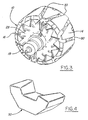
rotor 10 withfan 28 removed for clarity; - Figure 3 is the perspective view of
rotor 10 of Figure 2 withfan 28 included; and - Figure 4 is a perspective view of
magnetic inserts 30 of Figures 1, 2 and 3. -
- Referring to Figures 1, 2 and 3, a
rotor 10 and a portion of astator 12 for an alternator according to one embodiment of the present invention are illustrated.Stator 12 is a conventional stator known in the art of alternators. -
Rotor 10 comprises twopole pieces shaft 18. One skilled in the art of electrical machines will recognisepole pieces pole pieces terminals slip ring 19.Slip ring 19 is mounted onshaft 18 for rotation therewith. - Coupled to the back of
pole piece 14, preferably by welding, is afan 26. Also, coupled to the back ofpole piece 16 is afan 28. -
Rotor 10 also comprisesmagnetic inserts 30. Eachmagnetic insert 30 extends between two consecutive pole fingers of one pole piece and under the tip of a pole finger of the other pole piece. Further, eachmagnetic insert 30 preferably has two surfaces (for example,surfaces 38 and 40) which face radially outward fromrotor 10. Eachmagnetic insert 30 is fixed against outward radial movement by the pole finger tip under which thatmagnetic insert 30 is located. Further, eachmagnetic insert 30 is fixed against axial movement by theappropriate fan Fans magnetic inserts 30 with which the fans are adjacent. -
Magnetic inserts 30 will now be more fully described with reference to Figure 4.Magnetic inserts 30 are preferably made of permanent magnet material. Further, rare earth permanent magnet material is preferably used due to its superior magnetic qualities. However, other permanent magnet material such as ceramic permanent magnet material can also be used. In fact, a trade-off of cost versus performance in the design of aspecific rotor 10 may lead a designer to choose a less expensive magnetic material than rare earth magnetic material.Magnetic insert 30 has a profile which allows it to fit under the tip of a pole finger ofpole pieces - If added toughness of
magnetic inserts 30 is desirable to resist breakage ofmagnetic inserts 30 during assembly ofrotor 10,magnetic inserts 30 can be overmoulded with a non-magnetic material such as a polymer. -
Rotor 10 can be assembled as follows (refer now to Figure 1).Pole pieces shaft 18. Themagnetic inserts 30 are then pressed into place from the sides ofrotor 10. Finally,fans pole pieces magnetic inserts 30 are now fixed in place. It is apparent that this method of assemblingrotor 10 is not a drastic departure from the assembly method of a conventional alternator rotor. As a result, the design of this embodiment of the present invention is amenable to mass production. - A number of alternate assembly methods for
rotor 10 are possible. For example, other members thanfans pole pieces magnetic inserts 30 to prevent axial movement ofmagnetic inserts 30. As a further example, adhesive can be applied tomagnetic inserts 30 to supplement the function of the fans or other members, or to altogether eliminate the requirement of the fans or other members to prevent axial movement ofmagnetic inserts 30. - If
magnetic inserts 30 are made of permanent magnet material, it is preferable that they be magnetised after the above-described assembly ofrotor 10 occurs. Magnetisingmagnetic inserts 30 prior to assembly makes assembly ofrotor 10 more difficult, andmagnetic inserts 30 may tend to attract contaminants (metal shavings and the like). Postassembly magnetisation ofmagnetic inserts 30 can accomplished by using a magnetising machine, with the pole pieces of the assembledrotor 10 being the flux path. - The orientation of the magnetisation of
magnetic inserts 30 is described with reference to Figure 2. Each of the fingers ofpole pieces rotor 10 is energised with current of the intended polarity. For example,finger 32 may be a south magnetic pole andfinger 33 may be a north magnetic pole.Magnetic inserts 30 are preferably polarised such that the radially-outward portion of eachmagnetic insert 30 is of the same polarity as the polarity of the pole finger under which thatmagnetic insert 30 is located. For example, consider the case in whichfinger 33 is a north magnetic pole. Then,magnetic insert 30A will be magnetised such that its radiallyinward portion 37 is south and its radially outward portion (which comprisessurfaces 38 and 40) is north. - With respect to regulation of the output voltage of an
alternator comprising rotor 10, testing has suggested that a conventional voltage regulator can be used to control the field current of the alternator. That is, unidirectional current control (not bidirectional) in the field coil will likely suffice with the present invention. Testing has indicated that with no field current, there is very little output from the alternator, despite the considerable improvement in alternator output effected bymagnetic inserts 30 when field current is applied. Because of the very small output of the alternator in the absence of field current, no bidirectional control of field current (to prevent output of the alternator from being too great at high alternator speeds) is expected to be necessary. - The present invention has been observed to have at least three performance advantages. First, the power output attainable from an
alternator containing rotor 10 is significantly increased over an alternator of comparable physical size. Second,magnetic inserts 30 reduce acoustic noise associated with axial airflow throughrotor 10. "12th-order" and "18th-order" noise have been observed to be significantly reduced in arotor 10 according to one embodiment of the present invention. Third,magnetic inserts 30 provide support for the tips of the pole fingers (such aspole fingers 32 and 34) ofrotor 10. Thus, the vibration of the tips of the pole fingers asrotor 10 rotates, due to magnetic attraction to stator 12 of the alternator (Fig. 1), is reduced. The result is a reduction in the acoustic noise associated with that vibration of the pole finger tips.
Claims (15)
- A rotor (10) for an electrical machine, said rotor (10) comprising:characterised in that;a first pole piece (14) having a body defining an axis of rotation, and a plurality of pole fingers (33) each having an axially-extending portion terminating in a tip;a second pole piece (16) further having a body defining an axis of rotation coincident with the axis of said first pole piece, and a plurality of pole fingers (32) each having an axially-extending portion terminating in a tip, the pole fingers (33) of said first pole piece (14) intermeshed with the pole fingers (32) of said second pole piece (16); anda plurality of magnets (30), fixed against outward radial movement by the pole finger under which each magnet (30) is located, said magnets (30) each having at least one surface (38,40) facing radially outward from said rotor (10);
each said magnet (30) extends between two consecutive pole fingers (32 or 33) of one pole piece (14 or 16) and under the tip of a pole finger of the other pole piece (14 or 16). - A rotor (10) as claimed in claim 1, wherein said magnets (30) are permanent magnets.
- A rotor (10) as claimed in claim 2, further comprising:a member (26 or 28) mounted to said first pole piece (14), wherein said member has portions which impede axial movement of at least one of said permanent magnets (30).
- A rotor (10) as claimed in claim 3, wherein said member (26 or 28) is a fan.
- A rotor (10) as claimed in claim 2, wherein said permanent magnets (30) are adhesively bonded in place.
- A rotor (10) as claimed in claim 2, wherein said permanent magnets (30) each have a radially-outward portion and a radially-inward portion, said portions having opposite magnetic polarities.
- A rotor (10) as claimed in claim 6, wherein each said magnet (30) has two said surfaces (38,40) facing radially outward, one said surface (38,40) on each side of said finger (32 or 33) under whose end said magnet (30) is located.
- A rotor (10) as claimed in claim 2, wherein said permanent magnets (30) are rare earth permanent magnets or ceramic permanent magnets.
- A rotor (10) as claimed in claim 2, wherein said permanent magnets (30) are overmoulded with a non-magnetic material.
- A method for assembling a rotor (10) for an electrical machine, said method comprising the steps of;characterised in that;mounting a first pole piece (14), a second pole piece (16) and a field coil on a shaft (18) to create an assembly, said first pole piece (14) and said second pole piece (16) having pole fingers (32, 33) with each having an axially-extending portion with a tip said pole fingers (33) of said first pole piece (14) intermeshing with said pole fingers (32) of said second pole piece (16);inserting unmagnetised permanent magnet inserts (30) into said assembly, each said insert (30) being fixed against outward radial movement by the pole finger under which the magnet (30) is located and having a portion placed below a said tip of a said pole finger (32,33); andmagnetising said permanent magnet inserts (30);
each said magnet insert (30) extends between two consecutive pole fingers (32 or 33) of one pole piece (14 or 16) and under the tip of a pole finger (32 or 33) of the other pole piece (14 or 16). - A method for assembling a rotor (10) as claimed in claim 10, further comprising the step of mounting a member (26 or 28) to at least one of said pole pieces (14,16) such that said member impedes removal of at least some of said permanent magnet inserts (30).
- A method for assembling a rotor (10) as claimed in claim 11, wherein said member (26 or 28) is a fan.
- A method for assembling a rotor (10) as claimed in claim 12, wherein said fan (26 or 28) is welded to said pole piece.
- A method for assembling a rotor (10) as claimed in claim 10, wherein said permanent magnet inserts (30) are adhesively bonded in place.
- An alternator comprising:characterised in that;a stator (12) ;a rotor (10) rotatably mounted within said alternator and across an air gap from said stator (12), said rotor (10) further comprising:a first pole piece (14) having a body defining an axis of rotation, and a plurality of fingers (33) each having an axially-extending portion terminating in a tip;a second pole piece (16) further having a body defining an axis of rotation coincident with the axis of said first pole piece (14), and a plurality of pole fingers (32) each having an axially-extending portion terminating in a tip, the pole fingers (33) of said first pole piece (14) intermeshed with the pole fingers (32) of said second pole piece (16); and a plurality of magnets (30), fixed against outward radial movement by the pole finger under which each magnet (30) is located, said magnets (30) each having at least one surface (38,40) facing radially outward from said rotor (10);
each said magnet (30) extends between two consecutive pole fingers (32 or 33) of one pole piece (14 or 16) and under the tip of a pole finger (32 or 33) of the other pole piece (14 or 16).
Applications Claiming Priority (2)
| Application Number | Priority Date | Filing Date | Title |
|---|---|---|---|
| US08/405,102 US5543676A (en) | 1995-03-16 | 1995-03-16 | Rotating electrical machine with magnetic inserts |
| US405102 | 1995-03-16 |
Publications (3)
| Publication Number | Publication Date |
|---|---|
| EP0732795A2 EP0732795A2 (en) | 1996-09-18 |
| EP0732795A3 EP0732795A3 (en) | 1998-04-08 |
| EP0732795B1 true EP0732795B1 (en) | 2002-04-03 |
Family
ID=23602286
Family Applications (1)
| Application Number | Title | Priority Date | Filing Date |
|---|---|---|---|
| EP96301107A Expired - Lifetime EP0732795B1 (en) | 1995-03-16 | 1996-02-19 | Rotating electrical machine |
Country Status (4)
| Country | Link |
|---|---|
| US (1) | US5543676A (en) |
| EP (1) | EP0732795B1 (en) |
| JP (1) | JPH08308190A (en) |
| DE (1) | DE69620284T2 (en) |
Families Citing this family (63)
| Publication number | Priority date | Publication date | Assignee | Title |
|---|---|---|---|---|
| US5793144A (en) * | 1993-08-30 | 1998-08-11 | Nippondenso Co., Ltd. | Rotor for a rotating electric machine |
| DE19632219A1 (en) * | 1996-08-09 | 1998-02-12 | Bosch Gmbh Robert | Claw pole generator |
| US5892313A (en) * | 1996-10-04 | 1999-04-06 | Ford Motor Company | Rotating electrical machine with permanent magnet inserts |
| DE19642784A1 (en) * | 1996-10-17 | 1998-04-23 | Bosch Gmbh Robert | Claw pole generator |
| USD401319S (en) | 1997-05-05 | 1998-11-17 | Fanco, Inc. | Alternator fan |
| DE69804284T3 (en) * | 1997-09-26 | 2009-07-23 | DENSO CORPORATION, Kariya-shi | vehicle generator |
| DE69801475T2 (en) * | 1997-09-26 | 2002-05-16 | Denso Corp., Kariya | Automotive alternator |
| JPH11127561A (en) * | 1997-10-22 | 1999-05-11 | Denso Corp | Rotor of rotating machine with magnet and manufacturing method thereof |
| JP3541920B2 (en) * | 1997-10-27 | 2004-07-14 | 三菱電機株式会社 | Rotor of rotating electric machine and method of manufacturing the same |
| US5886451A (en) * | 1997-10-30 | 1999-03-23 | Ford Motor Company | Wire routing design for a rotor of an electrical machine |
| DE19802785A1 (en) * | 1998-01-26 | 1999-08-05 | Bosch Gmbh Robert | Synchronous machine, in particular generator for a motor vehicle |
| DE19802784C2 (en) * | 1998-01-26 | 2003-02-20 | Bosch Gmbh Robert | Synchronous machine, in particular generator for a motor vehicle |
| DE29801184U1 (en) * | 1998-01-26 | 1999-05-20 | Robert Bosch Gmbh, 70469 Stuttgart | Synchronous machine, in particular generator for a motor vehicle |
| US5965967A (en) * | 1998-07-06 | 1999-10-12 | Ford Global Technologies, Inc. | Rotor for an electrical machine |
| JP2000032719A (en) * | 1998-07-09 | 2000-01-28 | Mitsubishi Electric Corp | AC generator for vehicles |
| KR20000013662A (en) * | 1998-08-12 | 2000-03-06 | 에릭 발리베 | Alternator for a vehicle |
| US6274939B1 (en) | 1998-09-11 | 2001-08-14 | American Electronic Components | Resin ceramic compositions having magnetic properties |
| JP2000092800A (en) * | 1998-09-16 | 2000-03-31 | Denso Corp | AC generator for vehicles |
| US6172441B1 (en) | 1999-06-28 | 2001-01-09 | Visteon Global Technologies, Inc. | Rotor assembly |
| US6703741B1 (en) | 1999-09-20 | 2004-03-09 | Ecoair Corp. | Permanent magnet rotor portion for electric machines |
| US6307297B1 (en) * | 2000-05-05 | 2001-10-23 | Visteon Global Technologies, Inc. | Recessed alternator pole piece |
| US6359366B1 (en) | 2000-05-09 | 2002-03-19 | Ford Global Technologies, Inc. | Hybrid permanent magnet/synchronous machines |
| US6426581B1 (en) | 2000-05-22 | 2002-07-30 | Ford Motor Company | Magnet retainer ring for vehicle alternators |
| DE60102872T2 (en) | 2000-07-26 | 2005-03-31 | Denso Corp., Kariya | Brushless rotating electrical machine with an arrangement for cooling the stator |
| SG103299A1 (en) | 2000-08-04 | 2004-04-29 | Seagate Technology Llc | Low cost overmolded magnet and pole assembly |
| US6516770B1 (en) * | 2000-09-27 | 2003-02-11 | Ford Global Technologies, Inc. | Balance shaft and alternator assembly for an automotive vehicle |
| JP4300702B2 (en) | 2000-10-25 | 2009-07-22 | 株式会社デンソー | AC generator field rotor |
| US6555944B1 (en) | 2000-11-09 | 2003-04-29 | Visteon Global Technologies, Inc. | Deflection resisting rotor assembly |
| US6747384B2 (en) * | 2002-01-24 | 2004-06-08 | Visteon Global Technologies, Inc. | Alternator hybrid magnet rotor design |
| US20030183954A1 (en) * | 2002-03-15 | 2003-10-02 | Wolf Ronald J. | Magnetic resin composition and method of processing |
| JP3964302B2 (en) * | 2002-10-15 | 2007-08-22 | 三菱電機株式会社 | Rotating electrical machine rotor |
| US20050057106A1 (en) * | 2002-12-10 | 2005-03-17 | Ballard Power Systems Corporation | Methods and systems for electric machines having windings |
| US6724116B1 (en) * | 2002-12-20 | 2004-04-20 | Visteon Global Technologies, Inc. | Alternator permanent magnet rotor design |
| JP3964378B2 (en) * | 2003-10-23 | 2007-08-22 | 三菱電機株式会社 | Rotating electric machine for vehicles |
| JP3917967B2 (en) * | 2003-10-27 | 2007-05-23 | 三菱電機株式会社 | Rotating electrical machine rotor |
| US6989622B1 (en) | 2004-11-23 | 2006-01-24 | Visteon Global Technologies, Inc. | Alternator having claw-pole rotor |
| JP4410159B2 (en) * | 2005-06-24 | 2010-02-03 | 三菱電機株式会社 | AC rotating electric machine |
| EP2073361B1 (en) * | 2006-10-10 | 2017-08-09 | Mitsubishi Electric Corporation | Dynamoelectric machine |
| JP4680221B2 (en) * | 2007-03-26 | 2011-05-11 | 三菱電機株式会社 | Rotating electric machine |
| FR2916104B1 (en) * | 2007-05-11 | 2009-07-31 | Valeo Equip Electr Moteur | METHOD FOR MANUFACTURING A ROTOR OF A ROTATING ELECTRIC MACHINE, IN PARTICULAR AN ALTERNATOR |
| US7560851B2 (en) * | 2007-06-20 | 2009-07-14 | Mitsubishi Electric Corporation | Dynamoelectric machine and manufacturing method therefor |
| WO2009028228A1 (en) * | 2007-08-28 | 2009-03-05 | Mitsubishi Electric Corporation | Dynamo- electric machine |
| JP4912258B2 (en) | 2007-09-11 | 2012-04-11 | 三菱電機株式会社 | Rotating electric machine |
| JP4650849B2 (en) * | 2008-02-13 | 2011-03-16 | 三菱電機株式会社 | Rotating electric machine |
| US8304951B2 (en) * | 2008-02-13 | 2012-11-06 | Mitsubishi Electric Corporation | Dynamoelectric machine |
| EP2244362B1 (en) * | 2008-02-13 | 2012-12-19 | Mitsubishi Electric Corporation | Dynamoelectric machine |
| CN101978583B (en) | 2008-03-21 | 2013-02-27 | 三菱电机株式会社 | Rotating electrical machine for vehicle |
| WO2009122586A1 (en) * | 2008-04-04 | 2009-10-08 | 三菱電機株式会社 | Rotating electrical machine |
| CN102171911B (en) * | 2008-10-01 | 2013-01-30 | 三菱电机株式会社 | Revolving electric machine |
| DE112008004070B4 (en) * | 2008-11-10 | 2020-09-03 | Mitsubishi Electric Corp. | Dynamo-electric machine |
| JP2010183694A (en) * | 2009-02-04 | 2010-08-19 | Mitsubishi Electric Corp | Rotating electrical machine |
| FR2959362B1 (en) * | 2010-04-23 | 2012-05-04 | Valeo Equip Electr Moteur | ROTOR OF ROTATING ELECTRIC MACHINE WITH INTERPOLAR STRUCTURES |
| DE102011085429A1 (en) | 2011-10-28 | 2013-05-02 | Robert Bosch Gmbh | Electric machine, in particular alternator |
| JP5869306B2 (en) * | 2011-11-11 | 2016-02-24 | アスモ株式会社 | Rotor and motor |
| DE102012021109B4 (en) | 2011-10-31 | 2023-04-27 | Denso Corporation | rotor and engine |
| DE102012021048A1 (en) | 2011-10-31 | 2013-05-02 | Asmo Co., Ltd. | Rotor and motor |
| DE102012021049A1 (en) * | 2011-10-31 | 2013-05-02 | Asmo Co., Ltd. | Rotor and motor |
| US9577496B2 (en) * | 2012-11-13 | 2017-02-21 | Asmo Co., Ltd. | Rotor and brushless motor with rotation position detection |
| US9577501B2 (en) | 2013-04-05 | 2017-02-21 | Remy Technologies, Llc | Claw pole rotor with cavity for minimizing flux leakage |
| US10253676B2 (en) * | 2013-12-20 | 2019-04-09 | Magna Powertrain Bad Homburg GmbH | Molded rotor for cooling fan motor |
| FR3018404B1 (en) * | 2014-03-04 | 2017-09-08 | Valeo Equip Electr Moteur | MAGNETIC ELEMENT SUPPORT FOR ROTOR WITH ROTORS OF ROTATING ELECTRIC MACHINE AND ROTOR WITH CLUTCHES OF ROTATING ELECTRIC MACHINE COMPRISING SUCH A SUPPORT |
| FR3028359B1 (en) * | 2014-11-12 | 2018-05-18 | Valeo Equipements Electriques Moteur | ROTOR OF ROTATING ELECTRIC MACHINE |
| DE102018126180A1 (en) * | 2017-11-06 | 2019-05-09 | Borgwarner Inc. | Claw pole with shaped claw pole segments |
Citations (1)
| Publication number | Priority date | Publication date | Assignee | Title |
|---|---|---|---|---|
| JPH0556616A (en) * | 1991-08-28 | 1993-03-05 | Nippondenso Co Ltd | Ac generator for vehicle |
Family Cites Families (18)
| Publication number | Priority date | Publication date | Assignee | Title |
|---|---|---|---|---|
| US3346749A (en) * | 1965-02-02 | 1967-10-10 | Trw Inc | Self-excited brushless alternator |
| DE1488353A1 (en) * | 1965-07-15 | 1969-06-26 | Siemens Ag | Permanent magnet excited electrical machine |
| US3555327A (en) * | 1969-03-25 | 1971-01-12 | Ambac Ind | Permanent magnet alternator with regulating means |
| CH640089A5 (en) * | 1980-11-26 | 1983-12-15 | Forces Motrices Neuchateloises | Alternating electric current generator and method of manufacturing same |
| DE3410760A1 (en) * | 1984-03-23 | 1985-09-26 | Robert Bosch Gmbh, 7000 Stuttgart | ELECTRIC GENERATOR, ESPECIALLY FOR VEHICLES |
| DE3704156A1 (en) * | 1987-02-11 | 1988-08-25 | Bosch Gmbh Robert | AC GENERATOR WITH CLAW POLO ROTOR |
| JPH01129743A (en) * | 1987-11-12 | 1989-05-23 | Daikin Ind Ltd | Assembly of fan device |
| US5130595A (en) * | 1987-11-23 | 1992-07-14 | Chrysler Corporation | Multiple magnetic paths machine |
| US4980595A (en) * | 1987-11-23 | 1990-12-25 | Chrysler Corporation | Multiple magnetic paths machine |
| SE459833B (en) * | 1987-12-09 | 1989-08-07 | Astra Tech Ab | ROTATING ELECTRIC MACHINE |
| US4882515A (en) * | 1988-06-03 | 1989-11-21 | General Motors Corporation | Alternating current generator |
| US4959577A (en) * | 1989-10-23 | 1990-09-25 | General Motors Corporation | Alternating current generator |
| JP2946604B2 (en) * | 1990-02-26 | 1999-09-06 | 株式会社デンソー | AC generator |
| JP2785423B2 (en) * | 1990-03-13 | 1998-08-13 | 株式会社デンソー | Rotor of vehicle alternator and method of manufacturing the same |
| US5177391A (en) * | 1990-03-14 | 1993-01-05 | Nippondenso Co., Ltd. | Power generating apparatus |
| JP3237217B2 (en) * | 1991-08-08 | 2001-12-10 | 株式会社デンソー | Vehicle alternator rotor |
| DE69305118T2 (en) * | 1992-07-20 | 1997-02-06 | Gen Motors Corp | Process for the production of magnetic rotor parts |
| JP2548882B2 (en) * | 1993-05-07 | 1996-10-30 | 日本電装株式会社 | Vehicle alternator |
-
1995
- 1995-03-16 US US08/405,102 patent/US5543676A/en not_active Expired - Fee Related
-
1996
- 1996-01-23 JP JP8009161A patent/JPH08308190A/en not_active Ceased
- 1996-02-19 EP EP96301107A patent/EP0732795B1/en not_active Expired - Lifetime
- 1996-02-19 DE DE69620284T patent/DE69620284T2/en not_active Expired - Fee Related
Patent Citations (1)
| Publication number | Priority date | Publication date | Assignee | Title |
|---|---|---|---|---|
| JPH0556616A (en) * | 1991-08-28 | 1993-03-05 | Nippondenso Co Ltd | Ac generator for vehicle |
Also Published As
| Publication number | Publication date |
|---|---|
| EP0732795A2 (en) | 1996-09-18 |
| US5543676A (en) | 1996-08-06 |
| JPH08308190A (en) | 1996-11-22 |
| EP0732795A3 (en) | 1998-04-08 |
| DE69620284T2 (en) | 2002-10-31 |
| DE69620284D1 (en) | 2002-05-08 |
Similar Documents
| Publication | Publication Date | Title |
|---|---|---|
| US5543676A (en) | Rotating electrical machine with magnetic inserts | |
| US6548931B2 (en) | Hybrid permanent magnet/synchronous machines | |
| US5925964A (en) | Rotor for a rotating electric machine | |
| US5793143A (en) | Rotor for an electrical machine | |
| US5892313A (en) | Rotating electrical machine with permanent magnet inserts | |
| US5483116A (en) | Rotor for a rotating electric machine | |
| US6548935B1 (en) | Clan pole generator | |
| EP0881755A3 (en) | Rotor positioning magnets | |
| EP1289101A3 (en) | Motor with two axially coupled reluctance and permanent magnet rotors | |
| JPH05207716A (en) | Rotor of ac generator for vehicle | |
| KR930702814A (en) | Rotor of brushless motor | |
| US6785951B2 (en) | Rotor assembly and method of making | |
| JP2785423B2 (en) | Rotor of vehicle alternator and method of manufacturing the same | |
| JP2003244875A (en) | Rotor assembly for alternator | |
| US6538358B1 (en) | Hybrid electrical machine with axially extending magnets | |
| US6455978B1 (en) | Hybrid twin coil electrical machine | |
| KR100251270B1 (en) | Damper winding of an elevator motor | |
| JP2002534044A (en) | Permanent magnet and magnetoresistive rotary electric machine with improved magnetic flux attenuation characteristics | |
| US20040080235A1 (en) | High power permanent magnet hybrid alternator rotor | |
| US7095154B2 (en) | Generator motor for vehicles | |
| JPS6259539B2 (en) | ||
| JPS61293142A (en) | High-speed synchronous rotary machine with rotor comprising permanent magnet for producing magnetic field vartical to diametrical direction | |
| JP2865091B2 (en) | Alternator and method of manufacturing the same | |
| JP2783264B2 (en) | AC generator | |
| JP2865094B2 (en) | AC generator |
Legal Events
| Date | Code | Title | Description |
|---|---|---|---|
| PUAI | Public reference made under article 153(3) epc to a published international application that has entered the european phase |
Free format text: ORIGINAL CODE: 0009012 |
|
| AK | Designated contracting states |
Kind code of ref document: A2 Designated state(s): DE FR GB |
|
| PUAL | Search report despatched |
Free format text: ORIGINAL CODE: 0009013 |
|
| AK | Designated contracting states |
Kind code of ref document: A3 Designated state(s): DE FR GB |
|
| 17P | Request for examination filed |
Effective date: 19980925 |
|
| 17Q | First examination report despatched |
Effective date: 20000913 |
|
| GRAG | Despatch of communication of intention to grant |
Free format text: ORIGINAL CODE: EPIDOS AGRA |
|
| REG | Reference to a national code |
Ref country code: GB Ref legal event code: IF02 |
|
| GRAG | Despatch of communication of intention to grant |
Free format text: ORIGINAL CODE: EPIDOS AGRA |
|
| GRAH | Despatch of communication of intention to grant a patent |
Free format text: ORIGINAL CODE: EPIDOS IGRA |
|
| GRAH | Despatch of communication of intention to grant a patent |
Free format text: ORIGINAL CODE: EPIDOS IGRA |
|
| GRAA | (expected) grant |
Free format text: ORIGINAL CODE: 0009210 |
|
| AK | Designated contracting states |
Kind code of ref document: B1 Designated state(s): DE FR GB |
|
| PG25 | Lapsed in a contracting state [announced via postgrant information from national office to epo] |
Ref country code: FR Free format text: LAPSE BECAUSE OF FAILURE TO SUBMIT A TRANSLATION OF THE DESCRIPTION OR TO PAY THE FEE WITHIN THE PRESCRIBED TIME-LIMIT Effective date: 20020403 |
|
| REF | Corresponds to: |
Ref document number: 69620284 Country of ref document: DE Date of ref document: 20020508 |
|
| EN | Fr: translation not filed | ||
| PLBE | No opposition filed within time limit |
Free format text: ORIGINAL CODE: 0009261 |
|
| STAA | Information on the status of an ep patent application or granted ep patent |
Free format text: STATUS: NO OPPOSITION FILED WITHIN TIME LIMIT |
|
| 26N | No opposition filed |
Effective date: 20030106 |
|
| PGFP | Annual fee paid to national office [announced via postgrant information from national office to epo] |
Ref country code: DE Payment date: 20060214 Year of fee payment: 11 |
|
| PGFP | Annual fee paid to national office [announced via postgrant information from national office to epo] |
Ref country code: GB Payment date: 20060221 Year of fee payment: 11 |
|
| GBPC | Gb: european patent ceased through non-payment of renewal fee |
Effective date: 20070219 |
|
| PG25 | Lapsed in a contracting state [announced via postgrant information from national office to epo] |
Ref country code: DE Free format text: LAPSE BECAUSE OF NON-PAYMENT OF DUE FEES Effective date: 20070901 |
|
| PG25 | Lapsed in a contracting state [announced via postgrant information from national office to epo] |
Ref country code: GB Free format text: LAPSE BECAUSE OF NON-PAYMENT OF DUE FEES Effective date: 20070219 |