EP0731771B1 - A sealing for a container device - Google Patents
A sealing for a container device Download PDFInfo
- Publication number
- EP0731771B1 EP0731771B1 EP19950908889 EP95908889A EP0731771B1 EP 0731771 B1 EP0731771 B1 EP 0731771B1 EP 19950908889 EP19950908889 EP 19950908889 EP 95908889 A EP95908889 A EP 95908889A EP 0731771 B1 EP0731771 B1 EP 0731771B1
- Authority
- EP
- European Patent Office
- Prior art keywords
- valve
- ring
- sealing
- container
- gas
- Prior art date
- Legal status (The legal status is an assumption and is not a legal conclusion. Google has not performed a legal analysis and makes no representation as to the accuracy of the status listed.)
- Expired - Lifetime
Links
- 238000007789 sealing Methods 0.000 title claims abstract description 46
- 239000007788 liquid Substances 0.000 claims abstract description 13
- 235000013405 beer Nutrition 0.000 claims abstract description 5
- 230000000717 retained effect Effects 0.000 abstract description 2
- 230000008878 coupling Effects 0.000 description 3
- 238000010168 coupling process Methods 0.000 description 3
- 238000005859 coupling reaction Methods 0.000 description 3
- 238000010276 construction Methods 0.000 description 2
- 239000000463 material Substances 0.000 description 2
- 230000004913 activation Effects 0.000 description 1
- 230000000694 effects Effects 0.000 description 1
- 239000013013 elastic material Substances 0.000 description 1
- 230000012447 hatching Effects 0.000 description 1
- 230000000149 penetrating effect Effects 0.000 description 1
- 230000002035 prolonged effect Effects 0.000 description 1
- 230000007704 transition Effects 0.000 description 1
Images



Classifications
-
- B—PERFORMING OPERATIONS; TRANSPORTING
- B67—OPENING, CLOSING OR CLEANING BOTTLES, JARS OR SIMILAR CONTAINERS; LIQUID HANDLING
- B67D—DISPENSING, DELIVERING OR TRANSFERRING LIQUIDS, NOT OTHERWISE PROVIDED FOR
- B67D1/00—Apparatus or devices for dispensing beverages on draught
- B67D1/08—Details
- B67D1/0829—Keg connection means
- B67D1/0831—Keg connection means combined with valves
- B67D1/0838—Keg connection means combined with valves comprising means for preventing blow-out on disassembly of the spear valve
-
- Y—GENERAL TAGGING OF NEW TECHNOLOGICAL DEVELOPMENTS; GENERAL TAGGING OF CROSS-SECTIONAL TECHNOLOGIES SPANNING OVER SEVERAL SECTIONS OF THE IPC; TECHNICAL SUBJECTS COVERED BY FORMER USPC CROSS-REFERENCE ART COLLECTIONS [XRACs] AND DIGESTS
- Y10—TECHNICAL SUBJECTS COVERED BY FORMER USPC
- Y10T—TECHNICAL SUBJECTS COVERED BY FORMER US CLASSIFICATION
- Y10T137/00—Fluid handling
- Y10T137/2931—Diverse fluid containing pressure systems
- Y10T137/3115—Gas pressure storage over or displacement of liquid
- Y10T137/3127—With gas maintenance or application
- Y10T137/314—Unitary mounting for gas pressure inlet and liquid outlet
Definitions
- the invention relates to a sealing for a container device of the type serving the purpose of distributing a liquid, e.g. draught beer, the sealing comprising a container, which under pressure of a gas, e.g. CO 2 , stores the liquid, and also a combined gas- and liquid valve being mounted in a neck ring which is fixed on the container and sealed in relation to this by means of a sealing ring which is placed between opposite ring faces on the valve and on the neck ring, respectively, whereby the container device is supplied with a security device comprising a slot arranged between the valve and the neck ring for relieving the overpressure in the container when dismounting the valve.
- a gas e.g. CO 2
- Such a container device is normally cleaned, filled and discharged with the valve mounted.
- a coupling head is fixed to the valve which through activation of the coupling head opens for passages between the inner part of the container and a gas source and a drawing off place, respectively for e.g. serving of draught beer.
- This overpressure may be of danger to an operator who is going to dismount a valve when replacing this latter, or when inspecting the inside of the container. If the valve is dismounted while it is loaded by the overpressure, there might be a risk that it, without specific security precautions, is shot out into the room with great force when it loosens catching with the neck ring. If it hits the operator in this proces he might be seriously injured.
- valve constructions therefore to-day are often supplied with security arrangement meant to provide for the fact that the overpressure is relieved before the the valve's engagement with the neck ring is released.
- valve at the slot has a ring-formed projection which protrudes from the outer perifery of the ring face of the valve with direction towards the ring face of the neck ring.
- This projection blocks for the radial deformation of the ring face and prevents the overpressure in the container from pressing some of the ring into the slot space between the valve and the neck ring.
- the opposite ring faces of the valve and the neck ring, respectively are plane and parallel.
- the projection has a length which is adequate lesser than the thickness of the mounted and possibly squeezed sealing ring. The length must, however, be large enough to be able to control the radial deformation of the ring to such an extend, that nothing of the ring can penetrate into the slot space between the valve and the neck ring and close for the passage of the gas into the open air.
- the sealing ring can have a square cross section and the projection a cylindrical inner side fitting to the outer side of the sealing ring, whereby at least that part of the sealing ring, which adjoins the projection is safely fixed against radial expansion.
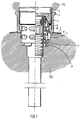
- Fig. 1 and 2 shows a container device, which is generally designated by the reference numeral 1.
- the device comprises a container 2 and a combined gas- and liquid valve 3.
- the container can e.g. be used for draugth beer which is to be kept under pressure by the gas CO 2 , as implied with hatching.
- valve 3 is per se of a well-known type and will therefore not be described further here.
- the valve is, by means of a thread 4, screwed into a neck ring 5, which is mounted on the container 2.
- the valve 3 and the neck ring 5 are sealed in relation to each other with a sealing ring 6, which in this case has a square cross section and is placed between the opposite, plane and parallel ring faces 14;15 on the valve and the neck ring, respectively.
- the valve shown in fig. 1 and 2 has a tilting catch 7 which can tilt into and out of an opening 8 in the valve house 9.
- the tilting catch is retained in the shown outwards tilted position by a resilient finger 10 as is located in the valve 3. Thereby it is prevented that the CO 2 overpressure in the container throws the valve out into the room when the valve is screwed off the thread of the neck ring by dismounting, in that the valve then will be stopped by the outwards tilted tilting catch, when this, as shown in fig. 2, is abbutting the under side of the neck ring.
- the tilting catch 7 Before the valve subsequently can be removed from the neck ring, the tilting catch 7 must be tilted into the opening 8, so that the valve 3 now unobstructed can be removed from the neck ring 5. This part of the dismounting takes place by means of a special tool (not shown) which pushes the finger 10 so far downwards that it will be pressed against an inwards turning flap 12 on the tilting catch 7 which thereby is tilted into the opening 8 and free of the neck ring 5.
- the projection is extending somewhat downwards along the outer side of the sealing ring, thereby preventing the former uncontrolled deformation of the sealing ring into the radial direction.
- the sealing ring can now no longer penetrate into the slot space 11 and close for the passage of the gas from the container into the open air, and the valve can be removed without danger for the operating personnel.
- the sealing ring 6 is placed between the two plane ring faces 14;15 on the valve and on the neck ring, respectively.
- the projection has a length which is lesser than the thickness of the sealing ring even in squeezed condition between the two ring faces.
- the ring-formed projection is to prevent the sealing ring from being radially deformed along its upper side while its under side very well can be deformed radially.
- An advantageous balancing between these two extremities takes place when the projection has a length of between 20% and 80%, preferably between 30% and 70% and especially between 40% and 60% of the thickness of the sealing ring in mounted state.
- the inwardly turning edge 16 of the projection can furthermore be rounded off.
Landscapes
- Devices For Dispensing Beverages (AREA)
- Gasket Seals (AREA)
- Closures For Containers (AREA)
- Package Closures (AREA)
- Auxiliary Devices For And Details Of Packaging Control (AREA)
- Supplying Of Containers To The Packaging Station (AREA)
Abstract
Description
- The invention relates to a sealing for a container device of the type serving the purpose of distributing a liquid, e.g. draught beer, the sealing comprising a container, which under pressure of a gas, e.g. CO2, stores the liquid, and also a combined gas- and liquid valve being mounted in a neck ring which is fixed on the container and sealed in relation to this by means of a sealing ring which is placed between opposite ring faces on the valve and on the neck ring, respectively, whereby the container device is supplied with a security device comprising a slot arranged between the valve and the neck ring for relieving the overpressure in the container when dismounting the valve.
- Such a container device is normally cleaned, filled and discharged with the valve mounted. On the consumption place a coupling head is fixed to the valve which through activation of the coupling head opens for passages between the inner part of the container and a gas source and a drawing off place, respectively for e.g. serving of draught beer.
- After use, when the container is empty, the coupling head is dismounted whereafter the gas- and liquid passages of the valve automatically are closed. In a container device, which usually is emptied for liquids, there will normally therefore remain a certain overpressure.
- This overpressure may be of danger to an operator who is going to dismount a valve when replacing this latter, or when inspecting the inside of the container. If the valve is dismounted while it is loaded by the overpressure, there might be a risk that it, without specific security precautions, is shot out into the room with great force when it loosens catching with the neck ring. If it hits the operator in this proces he might be seriously injured.
- In order to avoid accidents of this kind, the valve constructions therefore to-day are often supplied with security arrangement meant to provide for the fact that the overpressure is relieved before the the valve's engagement with the neck ring is released.
- However, it has shown that the normally square sealing ring between the valve and the neck ring as known from e.g. US. Patent No. 4,150,771 is liable to be deformed by the gas pressure in such a way that some of the sealing ring is penetrating into the slot space which is formed between the valve and the neck ring for passage of the gas during dismounting of the valve.
- Thereby the slot space is being closed so that the gas will not be able to escape this way, as intended, and in spite of said security precautions the unsuspecting operator, who relies on the liability of the security arrangement, might nevertheless risk to be hit by a valve which, when being dismounted, is shot out into the room by the overpressure not being relieved after all.
- It is therefore required to provide a sealing ring of the type mentioned in the opening paragraph where the sealing ring will not be deformed in such a way that some of the ring can penetrate into and close the slot space which exists between the valve and the neck ring for relieving the gas pressure during dismounting of the valve.
- The novel and unique features according to the invention, whereby this is achieved, is the fact that the valve at the slot has a ring-formed projection which protrudes from the outer perifery of the ring face of the valve with direction towards the ring face of the neck ring. This projection blocks for the radial deformation of the ring face and prevents the overpressure in the container from pressing some of the ring into the slot space between the valve and the neck ring. Thereby the gas is always secured a free passage through the slot space when the valve is being dismounted, and the valve is therefore guaranteed to be free from pressure load when the engagement of the valve with the neck ring is released.
- Normally, the opposite ring faces of the valve and the neck ring, respectively, are plane and parallel. In these cases it will be an advantage if the projection has a length which is adequate lesser than the thickness of the mounted and possibly squeezed sealing ring. The length must, however, be large enough to be able to control the radial deformation of the ring to such an extend, that nothing of the ring can penetrate into the slot space between the valve and the neck ring and close for the passage of the gas into the open air.
- By a particulary advantageous embodiment the sealing ring can have a square cross section and the projection a cylindrical inner side fitting to the outer side of the sealing ring, whereby at least that part of the sealing ring, which adjoins the projection is safely fixed against radial expansion.
- When the inner side of the projection is conical with convergence toward the ring face, the placing of the sealing ring to the valve is facilitated, and the side of the sealing ring, which is next to the ring face of the neck ring, is permitted to have a radial expansion which increases the sealing effect in relation to the neck ring, while the opposite side of the sealing ring simoultaneously is blocked against being radially deformed.
- If the free inwards turning edge of the projection is rounded off the material of the sealing ring is spared from over loading and its lifetime is prolonged.
- The invention will be explained more fully by the following description of an embodiment, which just serves as an example, with reference to the drawing, in which
- Fig. 1 shows a combined gas- and liquid valve, which is mounted in a neck ring on a container, which only can be seen in section,
- Fig. 2 shows the same, but where the valve is being dismounted and shown in the position where the valve's engagement with the neck ring just has been released,
- fig. 3 shows on an enlarged scale the sealing between the valve and the neck ring as shown in fig. 1,
- fig. 4 shows the same, but during dismounting,
- fig. 5 shows on an enlarged scale a section of a conventional sealing between a valve and a neck ring, and
- fig. 6 shows the same, but during dismounting.
- Fig. 1 and 2 shows a container device, which is generally designated by the reference numeral 1. The device comprises a
container 2 and a combined gas- andliquid valve 3. The container can e.g. be used for draugth beer which is to be kept under pressure by the gas CO2, as implied with hatching. - The
valve 3 is per se of a well-known type and will therefore not be described further here. In fig. 1 the valve is, by means of athread 4, screwed into aneck ring 5, which is mounted on thecontainer 2. Thevalve 3 and theneck ring 5 are sealed in relation to each other with asealing ring 6, which in this case has a square cross section and is placed between the opposite, plane andparallel ring faces 14;15 on the valve and the neck ring, respectively. - The valve shown in fig. 1 and 2 has a
tilting catch 7 which can tilt into and out of anopening 8 in the valve house 9. The tilting catch is retained in the shown outwards tilted position by aresilient finger 10 as is located in thevalve 3. Thereby it is prevented that the CO2 overpressure in the container throws the valve out into the room when the valve is screwed off the thread of the neck ring by dismounting, in that the valve then will be stopped by the outwards tilted tilting catch, when this, as shown in fig. 2, is abbutting the under side of the neck ring. - Before the valve subsequently can be removed from the neck ring, the
tilting catch 7 must be tilted into theopening 8, so that thevalve 3 now unobstructed can be removed from theneck ring 5. This part of the dismounting takes place by means of a special tool (not shown) which pushes thefinger 10 so far downwards that it will be pressed against aninwards turning flap 12 on thetilting catch 7 which thereby is tilted into the opening 8 and free of theneck ring 5. - While the operator in this way is manipulating the valve in order to screw it free from the neck ring and tilt the tilting catch into the
opening 8, the gas overpressure in the container is blown off via aslot space 11 between the valve and the neck ring. When the valve finally releases the engagement with the thread of the neck it will therefore be without load and can be removed without any risk. - In spite of the existence of this fact or similar security arrangement there is, however, a risk that the conventional sealing security arrangement, as shown in fig. 5 and 6, can fail due to the fact that part of the sealing ring is pressed into the
slot space 11 by the gas overpressure in the container. Thereby this slot space is blocked for the passage of gas and the overpressure in the container is remaining. - This situation is utmost dangerous because the operator relies on the fact that the security arrangement of the valve is a full guarantee for that dismounting of the valve is possible without any risk for himself to be hurt. He will therefore not be on guard to the possibility that the security arrangement nevertheless is set out of function and he can therefore unintended cause a serious accident when he is dismounting the valve.
- This risk is eliminated by the construction according to the invention, where there, as shown in fig. 3 and 4, is formed a ring formed
projection 13 on thevalve 3. - The projection is extending somewhat downwards along the outer side of the sealing ring, thereby preventing the former uncontrolled deformation of the sealing ring into the radial direction. The sealing ring can now no longer penetrate into the
slot space 11 and close for the passage of the gas from the container into the open air, and the valve can be removed without danger for the operating personnel. - As mentioned before, the
sealing ring 6 is placed between the two plane ring faces 14;15 on the valve and on the neck ring, respectively. In order to avoid that the projection will abbut thering face 15 of the neck ring, the projection has a length which is lesser than the thickness of the sealing ring even in squeezed condition between the two ring faces. - The ring-formed projection is to prevent the sealing ring from being radially deformed along its upper side while its under side very well can be deformed radially. An advantageous balancing between these two extremities takes place when the projection has a length of between 20% and 80%, preferably between 30% and 70% and especially between 40% and 60% of the thickness of the sealing ring in mounted state.
- In order to prevent the projection from cutting into the outer side of the sealing ring during the deformation of this latter, and thereby damage the material of the ring, the inwardly turning
edge 16 of the projection can furthermore be rounded off. - When the inner side of the projection is cylindrical, an adequate fitting is obtained between ring and projection in the full extension of the latter. By forming the inner side conical with convergence towards the ring face of the valve, the mounting of the sealing ring to the valve is facilitated and at the same time the transition from the radially undeformed upper side of the ring to the deformed under side side will be smoother whereby the elastic material of the ring is protected from being local overloaded.
Claims (7)
- A sealing for a container device (1) of the type serving the purpose of distributing a liquid, e.g. draught beer, the sealing comprising a container (2), which under pressure of a gas, e.g. CO2, stores the liquid, and also a combined gas- and liquid valve (3) being mounted in a neck ring (5) which is fixed on the container and sealed in relation to this by means of a sealing ring (6) which is placed between opposite ring faces (14;15) on the valve and on the neck ring, respectively, whereby the container device (1) is supplied with a security device comprising a slot (11) arranged between the valve (3) and the neck ring (5) for relieving the overpressure in the container when demounting the valve, characterize d in that the valve (3) at the slot (11) has a ring-formed projection (13) which protrudes from the outer perifery of the ring face (14) of the valve with direction towards the ring face (15) of the neck ring (5).
- A sealing according to claim 1, characterized in that the projection (13) having a length which is smaller than the thickness of the sealing ring (6) in mounted state.
- A sealing according to claim 1 or 2, characteriz ed in that the projection has a length of between 20% and 80%, preferably between 30% and 70%, and especially between 40% and 60% of the thickness of the sealing ring (6) in mounted state.
- A sealing according to claim 1, 2 or 3, characteri zed in that the projection (13) having a cylindrical inner side.
- A sealing according to each of the previous claims, char acterized in the inner side of the projection (13) being conical with convergence towards the ring face (15) of the valve.
- A sealing according to each of the previous claims, char acterized in that the inwards turning free edge (16) of the projection (13) is being rounded off.
- A sealing ring according to each of the previous claims, c haracterized in that the sealing ring (6) having a square cross section.
Applications Claiming Priority (3)
| Application Number | Priority Date | Filing Date | Title |
|---|---|---|---|
| DK15394 | 1994-02-07 | ||
| DK153/94 | 1994-02-07 | ||
| PCT/DK1995/000057 WO1995021120A1 (en) | 1994-02-07 | 1995-02-07 | A sealing for a container device |
Publications (2)
| Publication Number | Publication Date |
|---|---|
| EP0731771A1 EP0731771A1 (en) | 1996-09-18 |
| EP0731771B1 true EP0731771B1 (en) | 1997-12-10 |
Family
ID=8090362
Family Applications (1)
| Application Number | Title | Priority Date | Filing Date |
|---|---|---|---|
| EP19950908889 Expired - Lifetime EP0731771B1 (en) | 1994-02-07 | 1995-02-07 | A sealing for a container device |
Country Status (10)
| Country | Link |
|---|---|
| US (1) | US5713496A (en) |
| EP (1) | EP0731771B1 (en) |
| JP (1) | JP2702288B2 (en) |
| CN (1) | CN1070821C (en) |
| AT (1) | ATE161003T1 (en) |
| AU (1) | AU1705095A (en) |
| DE (1) | DE69501204T2 (en) |
| DK (1) | DK0731771T3 (en) |
| ES (1) | ES2110835T3 (en) |
| WO (1) | WO1995021120A1 (en) |
Families Citing this family (14)
| Publication number | Priority date | Publication date | Assignee | Title |
|---|---|---|---|---|
| GB2328204A (en) * | 1997-08-11 | 1999-02-17 | Kenneth Leonard Simpson | Keg and spear valve assembly |
| JP3908844B2 (en) * | 1998-01-20 | 2007-04-25 | サントリー株式会社 | Method and apparatus for incorporating seal ring |
| WO1999048801A1 (en) * | 1998-03-24 | 1999-09-30 | Spears Limited | Blow-out preventing device for a spear valve |
| NL1008828C1 (en) * | 1998-04-07 | 1999-10-08 | Dispense Systems International | Stop valve for a pressure container. |
| USD424167S (en) * | 1999-04-02 | 2000-05-02 | Ecolab, Inc. | Dispensing system bung cup |
| USD425965S (en) * | 1999-04-02 | 2000-05-30 | Ecolab, Inc. | Dispensing system probe |
| US6463611B1 (en) | 1999-04-02 | 2002-10-15 | Ecolab, Inc. | Apparatus for dispensing incompatible chemicals to a common utilization point |
| US6311875B1 (en) | 2000-04-05 | 2001-11-06 | Snyder Industries, Inc. | Pressurized tank dispenser assembly |
| US6367660B1 (en) * | 2001-09-20 | 2002-04-09 | Chang Kung-Chien | Safety device for a double valve arrangement for beer keg |
| JP4085382B2 (en) * | 2003-04-16 | 2008-05-14 | 澁谷工業株式会社 | Inner lid removal device |
| US20050167454A1 (en) * | 2004-02-04 | 2005-08-04 | Mauricio Botero | Apparatus and method for dispensing content from a container |
| EP2030944A3 (en) | 2007-07-31 | 2009-04-22 | Micro Matic A/S | Extractor device adapted for insertion into an opening of a beverage container and beverage container provided with extractor device |
| GB201005994D0 (en) * | 2010-04-09 | 2010-05-26 | Petainer Lidkoeping Ab | Keg closure with safety mechanism |
| EP3392193B1 (en) * | 2017-04-19 | 2019-06-19 | Micro Matic A/S | Dispense head with pressure equalising valve |
Family Cites Families (13)
| Publication number | Priority date | Publication date | Assignee | Title |
|---|---|---|---|---|
| US3353724A (en) * | 1965-10-22 | 1967-11-21 | Mack S Johnston | Beer tapping device |
| US3473556A (en) * | 1967-04-03 | 1969-10-21 | Polytop Corp | Beer keg tapping device and seal |
| US3454199A (en) * | 1968-01-23 | 1969-07-08 | Metro Mfg Inc | Keg tapping structure |
| US3497114A (en) * | 1968-11-05 | 1970-02-24 | Mack S Johnston | Beer tapping device |
| US3861569A (en) * | 1970-05-19 | 1975-01-21 | Draft Systems | Beer tap |
| US3908861A (en) * | 1971-10-14 | 1975-09-30 | Mack S Johnston | Series tapper assembly and method |
| US4150771A (en) * | 1976-03-27 | 1979-04-24 | Gkn Sankey Limited | Beer keg tapping closure units |
| US4181143A (en) * | 1977-09-28 | 1980-01-01 | Draft Systems, Inc. | Valve assembly and coupler therefor |
| US4343325A (en) * | 1977-09-28 | 1982-08-10 | Draft Systems, Inc. | Valve assembly and coupler therefor |
| JPS57138225A (en) * | 1981-02-20 | 1982-08-26 | Fuji Xerox Co Ltd | Image information transmission system |
| US4450853A (en) * | 1981-07-21 | 1984-05-29 | Robert Dessenoix | Assembly for drawing off a liquid by means of a gas under pressure |
| US4715414A (en) * | 1985-02-11 | 1987-12-29 | Grundy Dispense Systems, Inc. | Concentric well-type extractor tube for filling containers with pressurized fluid |
| GB8623932D0 (en) * | 1986-10-06 | 1986-11-12 | Alumasc Ltd | Liquid dispense head |
-
1995
- 1995-02-07 ES ES95908889T patent/ES2110835T3/en not_active Expired - Lifetime
- 1995-02-07 EP EP19950908889 patent/EP0731771B1/en not_active Expired - Lifetime
- 1995-02-07 WO PCT/DK1995/000057 patent/WO1995021120A1/en not_active Ceased
- 1995-02-07 AT AT95908889T patent/ATE161003T1/en not_active IP Right Cessation
- 1995-02-07 AU AU17050/95A patent/AU1705095A/en not_active Abandoned
- 1995-02-07 US US08/571,987 patent/US5713496A/en not_active Expired - Lifetime
- 1995-02-07 CN CN95191522A patent/CN1070821C/en not_active Expired - Fee Related
- 1995-02-07 DE DE69501204T patent/DE69501204T2/en not_active Expired - Lifetime
- 1995-02-07 JP JP52033095A patent/JP2702288B2/en not_active Expired - Fee Related
- 1995-02-07 DK DK95908889T patent/DK0731771T3/en active
Also Published As
| Publication number | Publication date |
|---|---|
| DK0731771T3 (en) | 1998-05-04 |
| AU1705095A (en) | 1995-08-21 |
| ES2110835T3 (en) | 1998-02-16 |
| ATE161003T1 (en) | 1997-12-15 |
| DE69501204T2 (en) | 1998-04-16 |
| CN1141619A (en) | 1997-01-29 |
| CN1070821C (en) | 2001-09-12 |
| JP2702288B2 (en) | 1998-01-21 |
| EP0731771A1 (en) | 1996-09-18 |
| US5713496A (en) | 1998-02-03 |
| DE69501204D1 (en) | 1998-01-22 |
| JPH08511228A (en) | 1996-11-26 |
| WO1995021120A1 (en) | 1995-08-10 |
Similar Documents
| Publication | Publication Date | Title |
|---|---|---|
| US5713496A (en) | Sealing for a container device | |
| EP0489829B1 (en) | A valve arrangement | |
| US4712705A (en) | Tamper indicating cap seal for container valves | |
| US4022343A (en) | Protective device for compressed gas cylinders | |
| US6070365A (en) | Multiple dome single-panel explosion vent | |
| US4656793A (en) | Explosion cover plate especially explosion hatch | |
| EP0642983A1 (en) | Container and pressure sealing closure combination | |
| CA2305445A1 (en) | Closure assembly for pressurized containers | |
| US2112641A (en) | Safety vent valve | |
| US3121509A (en) | Damage resistant rupture disc assembly | |
| US3169658A (en) | Damage resistant rupture disc assembly | |
| US2580426A (en) | Warning means for safety discharge outlets | |
| US4733872A (en) | Fusible packing for a supply port of an accumulator | |
| US4793509A (en) | Bulk material container having a filter vent | |
| DK164832B (en) | VACUUM VALVE FOR USE IN A SECURITY PLANT TO REDUCE THE DANGER OF EMISSIONS FROM DAMAGE DURING THE WATER LINE ON TANK SHIPS | |
| US5653253A (en) | Safety arrangement | |
| US4508131A (en) | Safety valving for cargo tanks used for bulk transportation of hazardous commodities | |
| US5607001A (en) | Safety equipment for a tank having a system for collecting the gas expelled from the tank during loading | |
| US5435333A (en) | Thermally responsive pressure relief apparatus | |
| CA2473252C (en) | Plastic hydraulic hammer reduction system | |
| US3913614A (en) | Pressure relief structure for aerosol containers | |
| US6109314A (en) | Tap for compressed or liquefied gas | |
| US4819683A (en) | Pressure relief device | |
| CZ275295A3 (en) | Double valve | |
| EP0683749B1 (en) | Blocking arrangement |
Legal Events
| Date | Code | Title | Description |
|---|---|---|---|
| PUAI | Public reference made under article 153(3) epc to a published international application that has entered the european phase |
Free format text: ORIGINAL CODE: 0009012 |
|
| 17P | Request for examination filed |
Effective date: 19951208 |
|
| AK | Designated contracting states |
Kind code of ref document: A1 Designated state(s): AT BE CH DE DK ES FR GB GR IE IT LI LU MC NL PT SE |
|
| RAP1 | Party data changed (applicant data changed or rights of an application transferred) |
Owner name: MICRO MATIC A/S |
|
| 17Q | First examination report despatched |
Effective date: 19961028 |
|
| GRAG | Despatch of communication of intention to grant |
Free format text: ORIGINAL CODE: EPIDOS AGRA |
|
| GRAG | Despatch of communication of intention to grant |
Free format text: ORIGINAL CODE: EPIDOS AGRA |
|
| GRAH | Despatch of communication of intention to grant a patent |
Free format text: ORIGINAL CODE: EPIDOS IGRA |
|
| GRAH | Despatch of communication of intention to grant a patent |
Free format text: ORIGINAL CODE: EPIDOS IGRA |
|
| GRAA | (expected) grant |
Free format text: ORIGINAL CODE: 0009210 |
|
| AK | Designated contracting states |
Kind code of ref document: B1 Designated state(s): AT BE CH DE DK ES FR GB GR IE IT LI LU MC NL PT SE |
|
| ITF | It: translation for a ep patent filed | ||
| PG25 | Lapsed in a contracting state [announced via postgrant information from national office to epo] |
Ref country code: GR Free format text: LAPSE BECAUSE OF FAILURE TO SUBMIT A TRANSLATION OF THE DESCRIPTION OR TO PAY THE FEE WITHIN THE PRESCRIBED TIME-LIMIT Effective date: 19971210 |
|
| REF | Corresponds to: |
Ref document number: 161003 Country of ref document: AT Date of ref document: 19971215 Kind code of ref document: T |
|
| REG | Reference to a national code |
Ref country code: CH Ref legal event code: EP |
|
| REG | Reference to a national code |
Ref country code: CH Ref legal event code: NV Representative=s name: DIPL.-ING. ETH H. R. WERFFELI PATENTANWALT |
|
| REF | Corresponds to: |
Ref document number: 69501204 Country of ref document: DE Date of ref document: 19980122 |
|
| ET | Fr: translation filed | ||
| PG25 | Lapsed in a contracting state [announced via postgrant information from national office to epo] |
Ref country code: LU Free format text: LAPSE BECAUSE OF NON-PAYMENT OF DUE FEES Effective date: 19980207 |
|
| REG | Reference to a national code |
Ref country code: ES Ref legal event code: FG2A Ref document number: 2110835 Country of ref document: ES Kind code of ref document: T3 |
|
| PG25 | Lapsed in a contracting state [announced via postgrant information from national office to epo] |
Ref country code: SE Free format text: LAPSE BECAUSE OF FAILURE TO SUBMIT A TRANSLATION OF THE DESCRIPTION OR TO PAY THE FEE WITHIN THE PRESCRIBED TIME-LIMIT Effective date: 19980310 |
|
| REG | Reference to a national code |
Ref country code: PT Ref legal event code: SC4A Free format text: AVAILABILITY OF NATIONAL TRANSLATION Effective date: 19980116 |
|
| REG | Reference to a national code |
Ref country code: DK Ref legal event code: T3 |
|
| REG | Reference to a national code |
Ref country code: IE Ref legal event code: FG4D Free format text: 77857 |
|
| PG25 | Lapsed in a contracting state [announced via postgrant information from national office to epo] |
Ref country code: MC Free format text: LAPSE BECAUSE OF NON-PAYMENT OF DUE FEES Effective date: 19980831 |
|
| PLBQ | Unpublished change to opponent data |
Free format text: ORIGINAL CODE: EPIDOS OPPO |
|
| PLBI | Opposition filed |
Free format text: ORIGINAL CODE: 0009260 |
|
| PLBF | Reply of patent proprietor to notice(s) of opposition |
Free format text: ORIGINAL CODE: EPIDOS OBSO |
|
| 26 | Opposition filed |
Opponent name: DISPENSE SYSTEMS INTERNATIONAL ( DSI) B.V. Effective date: 19980908 |
|
| NLR1 | Nl: opposition has been filed with the epo |
Opponent name: DISPENSE SYSTEMS INTERNATIONAL ( DSI) B.V. |
|
| PLBF | Reply of patent proprietor to notice(s) of opposition |
Free format text: ORIGINAL CODE: EPIDOS OBSO |
|
| PLBQ | Unpublished change to opponent data |
Free format text: ORIGINAL CODE: EPIDOS OPPO |
|
| PLAB | Opposition data, opponent's data or that of the opponent's representative modified |
Free format text: ORIGINAL CODE: 0009299OPPO |
|
| R26 | Opposition filed (corrected) |
Opponent name: DISPENSE SYSTEMS INTERNATIONAL ( DSI) B.V. Effective date: 19980908 |
|
| NLR1 | Nl: opposition has been filed with the epo |
Opponent name: DISPENSE SYSTEMS INTERNATIONAL ( DSI) B.V. |
|
| PLBO | Opposition rejected |
Free format text: ORIGINAL CODE: EPIDOS REJO |
|
| APAC | Appeal dossier modified |
Free format text: ORIGINAL CODE: EPIDOS NOAPO |
|
| APAE | Appeal reference modified |
Free format text: ORIGINAL CODE: EPIDOS REFNO |
|
| APAC | Appeal dossier modified |
Free format text: ORIGINAL CODE: EPIDOS NOAPO |
|
| REG | Reference to a national code |
Ref country code: GB Ref legal event code: IF02 |
|
| APAC | Appeal dossier modified |
Free format text: ORIGINAL CODE: EPIDOS NOAPO |
|
| PLBN | Opposition rejected |
Free format text: ORIGINAL CODE: 0009273 |
|
| STAA | Information on the status of an ep patent application or granted ep patent |
Free format text: STATUS: OPPOSITION REJECTED |
|
| 27O | Opposition rejected |
Effective date: 20020109 |
|
| NLR2 | Nl: decision of opposition | ||
| APAH | Appeal reference modified |
Free format text: ORIGINAL CODE: EPIDOSCREFNO |
|
| PGFP | Annual fee paid to national office [announced via postgrant information from national office to epo] |
Ref country code: IE Payment date: 20090216 Year of fee payment: 15 Ref country code: DK Payment date: 20090202 Year of fee payment: 15 Ref country code: AT Payment date: 20090205 Year of fee payment: 15 |
|
| PGFP | Annual fee paid to national office [announced via postgrant information from national office to epo] |
Ref country code: PT Payment date: 20090123 Year of fee payment: 15 |
|
| PGFP | Annual fee paid to national office [announced via postgrant information from national office to epo] |
Ref country code: CH Payment date: 20090204 Year of fee payment: 15 |
|
| PGFP | Annual fee paid to national office [announced via postgrant information from national office to epo] |
Ref country code: BE Payment date: 20090204 Year of fee payment: 15 |
|
| PLAB | Opposition data, opponent's data or that of the opponent's representative modified |
Free format text: ORIGINAL CODE: 0009299OPPO |
|
| REG | Reference to a national code |
Ref country code: PT Ref legal event code: MM4A Free format text: LAPSE DUE TO NON-PAYMENT OF FEES Effective date: 20100809 |
|
| BERE | Be: lapsed |
Owner name: *MICRO MATIC A/S Effective date: 20100228 |
|
| REG | Reference to a national code |
Ref country code: CH Ref legal event code: PL |
|
| REG | Reference to a national code |
Ref country code: DK Ref legal event code: EBP |
|
| PG25 | Lapsed in a contracting state [announced via postgrant information from national office to epo] |
Ref country code: LI Free format text: LAPSE BECAUSE OF NON-PAYMENT OF DUE FEES Effective date: 20100228 Ref country code: CH Free format text: LAPSE BECAUSE OF NON-PAYMENT OF DUE FEES Effective date: 20100228 |
|
| REG | Reference to a national code |
Ref country code: IE Ref legal event code: MM4A |
|
| PG25 | Lapsed in a contracting state [announced via postgrant information from national office to epo] |
Ref country code: AT Free format text: LAPSE BECAUSE OF NON-PAYMENT OF DUE FEES Effective date: 20100207 |
|
| PG25 | Lapsed in a contracting state [announced via postgrant information from national office to epo] |
Ref country code: PT Free format text: LAPSE BECAUSE OF NON-PAYMENT OF DUE FEES Effective date: 20100809 Ref country code: IE Free format text: LAPSE BECAUSE OF NON-PAYMENT OF DUE FEES Effective date: 20100208 Ref country code: DK Free format text: LAPSE BECAUSE OF NON-PAYMENT OF DUE FEES Effective date: 20100228 |
|
| PG25 | Lapsed in a contracting state [announced via postgrant information from national office to epo] |
Ref country code: BE Free format text: LAPSE BECAUSE OF NON-PAYMENT OF DUE FEES Effective date: 20100228 |
|
| PGFP | Annual fee paid to national office [announced via postgrant information from national office to epo] |
Ref country code: IT Payment date: 20120221 Year of fee payment: 18 |
|
| PGFP | Annual fee paid to national office [announced via postgrant information from national office to epo] |
Ref country code: FR Payment date: 20130314 Year of fee payment: 19 Ref country code: ES Payment date: 20130226 Year of fee payment: 19 Ref country code: GB Payment date: 20130213 Year of fee payment: 19 Ref country code: DE Payment date: 20130214 Year of fee payment: 19 |
|
| PGFP | Annual fee paid to national office [announced via postgrant information from national office to epo] |
Ref country code: NL Payment date: 20130214 Year of fee payment: 19 |
|
| REG | Reference to a national code |
Ref country code: DE Ref legal event code: R119 Ref document number: 69501204 Country of ref document: DE |
|
| REG | Reference to a national code |
Ref country code: NL Ref legal event code: V1 Effective date: 20140901 |
|
| GBPC | Gb: european patent ceased through non-payment of renewal fee |
Effective date: 20140207 |
|
| PG25 | Lapsed in a contracting state [announced via postgrant information from national office to epo] |
Ref country code: NL Free format text: LAPSE BECAUSE OF NON-PAYMENT OF DUE FEES Effective date: 20140901 |
|
| REG | Reference to a national code |
Ref country code: FR Ref legal event code: ST Effective date: 20141031 |
|
| REG | Reference to a national code |
Ref country code: DE Ref legal event code: R119 Ref document number: 69501204 Country of ref document: DE Effective date: 20140902 |
|
| PG25 | Lapsed in a contracting state [announced via postgrant information from national office to epo] |
Ref country code: FR Free format text: LAPSE BECAUSE OF NON-PAYMENT OF DUE FEES Effective date: 20140228 Ref country code: GB Free format text: LAPSE BECAUSE OF NON-PAYMENT OF DUE FEES Effective date: 20140207 Ref country code: DE Free format text: LAPSE BECAUSE OF NON-PAYMENT OF DUE FEES Effective date: 20140902 |
|
| REG | Reference to a national code |
Ref country code: ES Ref legal event code: FD2A Effective date: 20150407 |
|
| PG25 | Lapsed in a contracting state [announced via postgrant information from national office to epo] |
Ref country code: ES Free format text: LAPSE BECAUSE OF NON-PAYMENT OF DUE FEES Effective date: 20140208 |
|
| PG25 | Lapsed in a contracting state [announced via postgrant information from national office to epo] |
Ref country code: IT Free format text: LAPSE BECAUSE OF NON-PAYMENT OF DUE FEES Effective date: 20140207 |