EP0731739B1 - Locking ring stripper plate assembly - Google Patents
Locking ring stripper plate assembly Download PDFInfo
- Publication number
- EP0731739B1 EP0731739B1 EP19930923276 EP93923276A EP0731739B1 EP 0731739 B1 EP0731739 B1 EP 0731739B1 EP 19930923276 EP19930923276 EP 19930923276 EP 93923276 A EP93923276 A EP 93923276A EP 0731739 B1 EP0731739 B1 EP 0731739B1
- Authority
- EP
- European Patent Office
- Prior art keywords
- stripper plate
- cap
- punch
- stripper
- assembly
- Prior art date
- Legal status (The legal status is an assumption and is not a legal conclusion. Google has not performed a legal analysis and makes no representation as to the accuracy of the status listed.)
- Expired - Lifetime
Links
- 230000002093 peripheral effect Effects 0.000 claims description 5
- 230000007246 mechanism Effects 0.000 description 11
- 230000008859 change Effects 0.000 description 3
- 238000000034 method Methods 0.000 description 3
- 230000008569 process Effects 0.000 description 3
- 238000004080 punching Methods 0.000 description 3
- 230000000712 assembly Effects 0.000 description 2
- 238000000429 assembly Methods 0.000 description 2
- 230000000881 depressing effect Effects 0.000 description 2
- 230000003993 interaction Effects 0.000 description 2
- 238000004519 manufacturing process Methods 0.000 description 2
- 230000013011 mating Effects 0.000 description 2
- 238000006049 ring expansion reaction Methods 0.000 description 2
- 241001364096 Pachycephalidae Species 0.000 description 1
- 239000011248 coating agent Substances 0.000 description 1
- 238000000576 coating method Methods 0.000 description 1
- 230000006835 compression Effects 0.000 description 1
- 238000007906 compression Methods 0.000 description 1
- 239000012530 fluid Substances 0.000 description 1
- 238000003780 insertion Methods 0.000 description 1
- 230000037431 insertion Effects 0.000 description 1
- 238000009434 installation Methods 0.000 description 1
- 230000014759 maintenance of location Effects 0.000 description 1
- 239000002184 metal Substances 0.000 description 1
- 230000004048 modification Effects 0.000 description 1
- 238000012986 modification Methods 0.000 description 1
- 238000000926 separation method Methods 0.000 description 1
Images




Classifications
-
- B—PERFORMING OPERATIONS; TRANSPORTING
- B21—MECHANICAL METAL-WORKING WITHOUT ESSENTIALLY REMOVING MATERIAL; PUNCHING METAL
- B21D—WORKING OR PROCESSING OF SHEET METAL OR METAL TUBES, RODS OR PROFILES WITHOUT ESSENTIALLY REMOVING MATERIAL; PUNCHING METAL
- B21D45/00—Ejecting or stripping-off devices arranged in machines or tools dealt with in this subclass
- B21D45/003—Ejecting or stripping-off devices arranged in machines or tools dealt with in this subclass in punching machines or punching tools
- B21D45/006—Stripping-off devices
-
- Y—GENERAL TAGGING OF NEW TECHNOLOGICAL DEVELOPMENTS; GENERAL TAGGING OF CROSS-SECTIONAL TECHNOLOGIES SPANNING OVER SEVERAL SECTIONS OF THE IPC; TECHNICAL SUBJECTS COVERED BY FORMER USPC CROSS-REFERENCE ART COLLECTIONS [XRACs] AND DIGESTS
- Y10—TECHNICAL SUBJECTS COVERED BY FORMER USPC
- Y10T—TECHNICAL SUBJECTS COVERED BY FORMER US CLASSIFICATION
- Y10T83/00—Cutting
- Y10T83/202—With product handling means
- Y10T83/2092—Means to move, guide, or permit free fall or flight of product
- Y10T83/2096—Means to move product out of contact with tool
- Y10T83/2135—Moving stripper timed with tool stroke
- Y10T83/215—Carried by moving tool element or its support
-
- Y—GENERAL TAGGING OF NEW TECHNOLOGICAL DEVELOPMENTS; GENERAL TAGGING OF CROSS-SECTIONAL TECHNOLOGIES SPANNING OVER SEVERAL SECTIONS OF THE IPC; TECHNICAL SUBJECTS COVERED BY FORMER USPC CROSS-REFERENCE ART COLLECTIONS [XRACs] AND DIGESTS
- Y10—TECHNICAL SUBJECTS COVERED BY FORMER USPC
- Y10T—TECHNICAL SUBJECTS COVERED BY FORMER US CLASSIFICATION
- Y10T83/00—Cutting
- Y10T83/202—With product handling means
- Y10T83/2092—Means to move, guide, or permit free fall or flight of product
- Y10T83/2096—Means to move product out of contact with tool
- Y10T83/2135—Moving stripper timed with tool stroke
- Y10T83/215—Carried by moving tool element or its support
- Y10T83/2155—Stripper biased against product
- Y10T83/2159—By spring means
-
- Y—GENERAL TAGGING OF NEW TECHNOLOGICAL DEVELOPMENTS; GENERAL TAGGING OF CROSS-SECTIONAL TECHNOLOGIES SPANNING OVER SEVERAL SECTIONS OF THE IPC; TECHNICAL SUBJECTS COVERED BY FORMER USPC CROSS-REFERENCE ART COLLECTIONS [XRACs] AND DIGESTS
- Y10—TECHNICAL SUBJECTS COVERED BY FORMER USPC
- Y10T—TECHNICAL SUBJECTS COVERED BY FORMER US CLASSIFICATION
- Y10T83/00—Cutting
- Y10T83/929—Tool or tool with support
- Y10T83/9457—Joint or connection
- Y10T83/9461—Resiliently biased connection
-
- Y—GENERAL TAGGING OF NEW TECHNOLOGICAL DEVELOPMENTS; GENERAL TAGGING OF CROSS-SECTIONAL TECHNOLOGIES SPANNING OVER SEVERAL SECTIONS OF THE IPC; TECHNICAL SUBJECTS COVERED BY FORMER USPC CROSS-REFERENCE ART COLLECTIONS [XRACs] AND DIGESTS
- Y10—TECHNICAL SUBJECTS COVERED BY FORMER USPC
- Y10T—TECHNICAL SUBJECTS COVERED BY FORMER US CLASSIFICATION
- Y10T83/00—Cutting
- Y10T83/929—Tool or tool with support
- Y10T83/9457—Joint or connection
- Y10T83/9473—For rectilinearly reciprocating tool
- Y10T83/9476—Tool is single element with continuous cutting edge [e.g., punch, etc.]
Definitions
- This invention relates to punch guide sleeve and stripper plate assemblies such as those usable with multiple-station turret punch machines.
- each punch station operates as a punch set holder for a removable punch set that includes a centrally disposed punch surrounded by a punch guide and biased by a punch spring.
- the operator may wish to change some or all of the punch set and die combinations from time to time. For instance, the operator may wish to utilize a different punch blade shape or size in a punch set. It is desirable to minimize the time required and make it simple to change the punch and die components, and thereby reduce down time for the punch machine.
- the punch guide may be provided with a stripper plate.
- the stripper plate has an opening such that a punch blade will fit snugly therethrough but, yet will be able to axially move freely through the opening.
- the punch guide is oriented with the stripper plate flush against the workpiece surface. Then, when the punch blade retracts from the workpiece, the edges of the workpiece around the punch hole will be prevented by the stripper plate from following the retracting punch blade.
- One such punch guide stripper plate configuration incorporates the stripper plate as an integral part of the punch guide itself. Since the size and shape of the stripper plate hole must coincide closely with the punch blade, however, each such punch guide may only be used with one matching punch. Consequently, interchanging punch and die combinations may be inconvenient, since the operator must change not only the die and punch, but the punch guide as well.
- Another configuration uses flattened metal clip or the like to retain a removable stripper plate at the end of a punch guide. This allows the use of a number of different punch blades with each guide, since only the stripper plate need be changed for each new punch blade.
- These spring clip structures have not provided completely satisfactory performance. Often, the workpiece surface will have a thin coating of oil or other fluid. When the stripper plate meets the workpiece surface, a suction may be created. When this occurs, the stripper plate may be pulled out of place and damage may result to the workpiece and to the stripper plate. Down time may also become a problem. Finally, these clips also tend to weaken with usage, aggravating the above-noted problems.
- commonly assigned U.S.-A-4,248,111 depicts a punch guide assembly that makes use of stripper plate holding tabs that are formed on clips attached parallel to the primary axis of the punch guide.
- a further locking ring stripper plate assembly according to the pre-characterising part of claim 1 is disclosed in commonly assigned U.S.-A-4,446,767 wherein a locking ring 13 is fitted in matching circumferential grooves in a stripper plate 12 in the punch guide sleeve 11.
- the free ends 31 of the locking ring 13 include tabs 32 that may be spread apart and locked into position by the locking ring expansion lock 14.
- an O-ring 25 in annular mating grooves in the punch guide sleeve and the stripper plate provides a snap fit of the stripper plate 21 to the punch guide 18.
- the '824 patent also illustrates a snap ring 38 for retaining stripper plate 36 in position. Such snap rings may not be strong and reliable enough to lock stripper plates in position.
- the '339 patent employs retainers 60 and spring-mounted elements 56 for engagement against v-shaped annular detent grooves 57 in the edge of the stripper plate 62. Attachment and removal involves loosening the retainers 60 and moving them aside to snap in or unsnap the spring-loaded catches 56 in or out of the grooves. The redundant attachment mechanism requires additional steps in releasing or locking the stripper plate.
- the '718 patent shows in Figures 5, 7 and 14 the use of spring clips 194 attached to the punch guide and engaging internally-threaded annual flanges 196 in the stripper plate 46 in a fashion similar to the '111 patent.
- Such spring clips may not be strong enough for large diameter punch sets and may weaken with repeated use.
- the '484 patent discloses a complex locking ring 80 with positioning springs 90 and 92 located within a groove and positioned between a pair of diametrically opposed pins 94, 96 that engage other pins, such as 98, to hold the ring 80 in the lock position.
- the stripper plate 74 is held in place in the locking ring by centrally extending flanges 109 and pin receiving slots 110 to cover the pins 74D.
- the locking ring 80 is turned about the axis of the punch assembly against the compression of the springs 90, 92, thereby aligning the pin receiving slots 110 with the pin 74D and allowing the stripper plate 74 to be removed and re-inserted in the fashion of a bayonet-lock mechanism. Then by pushing the stripper plate in and depressing release pin 112, the springs 90, 92 rotate locking ring 80 on the box 76 so the flanges 109 cover the pins 74D thereby holding the stripper plate 74 securely in place on the end of the punch assembly 10.
- This rotatable retaining ring and stripper plate assembly constitutes a number of small parts, such as pins and springs, that add to complexity and fabrication costs. Moreover, the stripper plate retaining ring itself is removed when the stripper plate is released which can lead to its loss or damage if dropped.
- stripper plate locking mechanisms that are easy and quick to use in releasing or attaching the stripper plate, do not include small loose parts and securely hold the stripper plate when locked.
- the invention disclosed herein constitutes a punch guide sleeve and stripper plate assembly allowing the stripper plate to be easily and securely affixed to and removed from the punch guide sleeve.
- This invention finds particular applicability with relatively wide punch guide sleeves. It may be manufactured economically, and does not require any special custom-made tools to operate or involve the separation of attachment components from the guide sleeve.
- the assembly differs most markedly from existing assemblies by the provision of a rotatable stripper plate cap which may be manually rotated with respect to the guide sleeve end from a locked to an unlocked position to secure and release the stripper plate through tightening and loosening an arcuate retaining means onto and away from the stripper plate.
- the retaining means is preferably substantially circular or rectangular in cross-section and is split to provide two unconnected ends that are attached to the stripper plate cap and the guide sleeve one another. When these two ends are drawn together in the locked position, the arcuate wire will be diametrally compressed for engagement with the stripper plate.
- a punch guide sleeve and stripper plate assembly which comprises the features defined in claim 1.
- the locking means further comprises a spring loaded button and catch arrangement that releasably locks the stripper cap in the locked position to maintain the retaining wire in contact with the annular edge portion of the stripper plate.
- the seat is formed in the end of the sleeve and the stripper cap is formed with a second inwardly directed annular surface for receiving the retaining wire between the second inwardly directed annular surface and the end of the sleeve in the unlocked position.
- the stripper cap is formed with a second annular surface defining the seat, the annular edge portion of the stripper plate comprises a groove extending around the side edge of the stripper plate for receiving the retaining wire in the locked position, and the stripper cap further comprises an annular slot extending around the stripper cap adjacent to the groove in the stripper plate positioned in the seat for receiving the retaining wire in the unlocked position.
- the locking ring stripper plate assembly of the present invention as illustrated in the figures is preferably implemented in relatively large diameter punch sets of the type disclosed in the '767 patent that have relatively large and heavy stripper plates, although the invention may be practiced in a variety of punch set types.
- Three preferred embodiments are illustrated in the figures and described, together with variations on the illustrated embodiments, as follows.
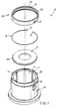
- FIG. 1 it illustrates in an exploded perspective view most of the components of the first preferred embodiment of the locking ring stripper plate assembly that are employed to hold the stripper plate 12 in the opening 14 of the punch guide sleeve 16 which itself is intended to be assembled into the punch set 10 in the cross-section drawing of FIG. 2.
- the stripper plate 12 is locked against the stripper plate seat 22 of the sleeve 16 by tightening the ring-shaped stripper plate retaining wire 18 in the space between the shoulder 24 inside the flange 11 of the stripper plate 12 and the inwardly extending lip 26 of the stripper cap 20 in a manner to be described hereafter.
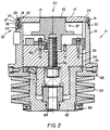
- FIG. 2 it illustrates in a cross-section view, the assembly of the components illustrated in FIG. 1 into a punch set 10.
- the punch set 10 illustrated in FIG. 2 includes the centrally-disposed punch 50, including the punch blade 52 extending through the stripper plate opening 13, the punch holder 54, the bolts 56, 58, 60, the punch driver 62, and a punch-length adjustment mechanism 64 described more completely in the above-referenced co-pending application.
- the assembly of the punch 50 and the particular configuration and operation of its components are not critical to the present invention and thus are only briefly described.
- the punch assembly spring 64 surrounds the punch driver 62 and is held in place by first and second collars 66 and 68 that are bolted to the sleeve 16 and the driver 62.
- the collar 66 when assembled to the sleeve 16, also bears against the annular flange 70 of the punch driver 62 to maintain all the components in the assembled state depicted in FIG. 2.
- the sleeve 16 is inserted in a punch holder in the turret of a punch press, and the ram of the punch press strikes the punch driver to force the punch blade through a work piece in the opening of a matching die.
- the spring 64 is thus compressed during the punching operation and operates to withdraw the blade 52 from the die and workpiece upon retraction of the ram.
- the stripper plate 12 operates to strip away the punched-out blank or debris that may attach to the blade 52 in a process well known in the prior art.
- the stripper plate 12 is attached to the seat 22 of the guide sleeve 16 inside flange 11 through the interaction of the retaining wire 18 with the shoulder 24 of the stripper plate 12 and the inwardly-extending lip 26 of the stripper cap 20.
- the stripper plate 12 has an outside diameter that fits within the inside diameter of the sleeve 16 and against the stripper plate seat 22.
- the height of the shoulder 24 matches the depth of the seat 22 so that the retaining wire 18 may be drawn against and over shoulder 24 when the ends 19 and 21 of the retaining wire 18 are drawn together by clockwise rotation of the stripper cap 20.
- the end 19 of the retaining wire 18 extends into a hole 17 in the flange 11 of the sleeve 16 adjacent to the stripper plate seat 22.
- the other end 21 of the retaining wire 18 extends into a hole 25 in the inwardly-extending lip 26 of the stripper cap 20.
- FIGs. 1 and 2 also show the locking mechanism for retaining the stripper cap 20 in the locked position.
- the locking mechanism 32 comprises the spring loaded button 34 and the coil spring 36 which biases the button 34 through the locking hole 27 in the stripper cap 20 in the locked position illustrated in FIG. 2.
- the operator depresses the button 34 against the biasing spring 36 to release it from locking hole 27 and rotates the stripper cap 20 in the counter-clockwise direction to draw the end 21 extending through the hole 25 away from the end 19 extending into the hole 17.
- the retaining wire 18 is drawn away from the shoulder 24 and inside the lip 26 until the stripper plate 12 falls free.
- the operator places it against the seat 22 so that the opening 13 accomodates the punch blade 52 and twists the cap 20 in the clockwise direction until the button 34 snaps through the locking hole 27. In this assembly and process, only the stripper plate 12 is released while the stripper cap 20 and the other described components remain attached to the guide sleeve 16.
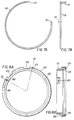
- FIGs. 3A-3C they illustrate the shape and configuration of the stripper cap 20 in accordance with the first embodiment of the present invention.
- the stripper cap 20 is circular in shape and comprises a wall 23 formed with the inwardly-extending lip 26 and an annular groove 31 for receiving the wave wire 30.
- the locking hole 27 extends through the wall 23 and receives the spring loaded locking button 34 as described above.
- FIG. 3C shows the hole 25 for receiving the end 21 of the retaining wire 18.
- a cutout 29 in the lip 26 is provided to allow the insertion of end 19 of wire 18 into the hole 17 with the stripper cap 20 assembled on the sleeve 16.
- FIGs. 4A and 4B illustrate the shape of the wave wire 30 that fits within the annular grooves 31 and 33.
- One end 35 of the wave wire 30 is intended to fit into a hole 37 extending radially inwardly in the sleeve 16 (shown in FIG. 2) to prevent the wave wire from rotating with the rotation of the cap 20.
- the so-stabilized wave wire thus tends to act as a spring guide to prevent the cap 20 side wall 23 from binding against the sleeve 16 and to secure the cap 20 to the sleeve 16.
- FIGs. 5A and 5B they illustrate in plan and side views the first embodiment retaining wire 18 and its ends 19 and 21.
- the retaining wire 18 generally extends in a circular shape through about 340° and is circular in cross-section.
- Punch sets and punch set holders formed in punch press turrets differ from manufacturer to manufacturer.
- Keyways and slots are formed in and extend along the punch sleeve interior or exterior surfaces to guide the reciprocating movements of the components of the punch set and the punch set with respect to the particular punch set holder during the punching operation.
- the keyways and guides thus stabilize and fit the punch set components together and/or to the punch set holder in the turret.
- sets of keyways allow the operator to select an orientation of a non-circular punch blade about its axis with respect to the punch guide to set it up to punch holes in workpieces at a desired angle, as is dconventional. Consequently, the embodiments of the present invention are realized in the context of these pre-existing limitations and restraints. Thus, while it would be desireable to employ a ring-shaped retaining wire to completely encircle the stripper plate, preexisting punch set structure may limit the ability to do so.
- the second embodiment is thus presented as an implementation of the present invention in punch sets that fit a further type of "thin turret" punch press.
- FIG. 6 it illustrates a portion of a punch set 110, and in particular the assembly of the stripper plate 112 to the sleeve 116 through the interaction of the stripper cap 120, the retaining wire 118 and the locking mechanism 132.
- the stripper plate 112 is circular and has an annular groove 170 extending around its peripheral side wall for receiving the retaining wire 118 when the stripper cap 120 is in the locked position.
- the stripper plate 112 rests in the sleeve seat 122.
- the stripper cap 120 has a side wall 123 that extends within the open end of the sleeve 116, rather than extending over sleeve 116 as shown in the first embodiment of FIGs. 1-5. Consequently, the locking mechanism 132 includes a push button 134 that extends through and is trapped within the side wall of the sleeve 116 and contacts a spring-loaded catch 172 that bears against the coil spring 136 trapped within the bore 174 in the side wall 123 of the stripper cap 120. The locking mechanism 132 is operated by depressing the button 134 to compress the coil spring 174 and move the sliding catch 172 into the recess 176.
- the cap 120 may be rotated to move the ends 119 and 121 apart and expand the diameter of the retaining wire 118.
- the retaining wire 118 thus moves from the annular groove 170 in the edge of the stripper plate 112 into the annular groove 178 in the cap 120, whereupon the stripper plate 112 is released.
- Reattachment of the stripper plate 112 is accomplished in the converse manner of positioning its edge against the stripper plate seat 122 and twisting the stripper cap 120 in the counter-clockwise direction to draw the ends 121 and 119 toward one another until the retaining wire 118 is drawn into the annular groove 170 and the sliding catch 172 snaps back into the locking hole 127 and into contact with the button 134.
- FIGs. 7A and 7B they illustrate the spring wire 118 in plan and side views.
- the spring wire 118 is formed as an arc of a circle of about 280° in view of particular restraints placed on the shape of the stripper cap 120 illustrated in FIGs. 8A-8C.
- keyways 102 and 104 must extend through the cap 120 where the retaining wire would pass, if the wire were extended around a greater circular arc.
- FIGs. 8A-8C the illustrate in top, side cross-sectional and bottom views the configuration of the stripper cap 120 shown assembled in the cross-section view of FIG. 6.
- FIG. 8B is a cross-section view taken along the lines III-III of FIG. 8A in order to illustrate the upward extending hole 125 for receiving the end 121 of retaining wire 118 and the downward extending bore 182 for receiving the other end 119 of retaining wire 118.
- the downward extending end 119 also fits in a bore 117 in sleeve 116 depicted in FIG. 6 and passes through the elongated slot 184.
- FIG. 8B also shows the annular groove 131 cut in the exterior side wall 123 surface of the cap 120 which mates with an annular groove 133 cut in the exterior surface of the sleeve 116 to accept the wave wire 30 depicted in FIGs. 3A and 3B.
- the end 35 of the wave wire 30 projects through the hole 180 to prevent it from slipping.
- the wave wire placed in the groove 131 and the matching annular groove 133 acts to both attach and slightly separate the mating surfaces of the stripper cap 120 and the guide sleeve 116 to inhibit binding that might otherwise occur when the stripper cap is twisted back and forth on the guide sleeve surface..
- the retaining force may be distributed as equally as possible against the shoulder 24 through 360°, this may be accomplished by splitting the retaining wire 18 into two or more arcuate shaped sections each attached at the free ends thereof to the sleeve 16 and the cap 20 in the manner as described above.
- the retaining wire 18 may be split into two arcs, and each wire may be attached at its ends to a further hole in the cap and in the sleeve end appropriately positioned about 180° apart from the locations depicted.
- first and second retaining wires 218 and 218' are formed of square cross-section wires having ends 219, 219' and 221, 221' that fit into the holes 217, 217'and 225, 225', respectively.
- the wires 218, 218' are tightened around the stripper plate 212 by clockwise rotation of the cap 220 with respect to the sleeve 216 and loosened by counter-clockwise rotation of these components.
Landscapes
- Engineering & Computer Science (AREA)
- Mechanical Engineering (AREA)
- Punching Or Piercing (AREA)
- Chairs For Special Purposes, Such As Reclining Chairs (AREA)
- Perforating, Stamping-Out Or Severing By Means Other Than Cutting (AREA)
Abstract
Description
- Technical Field--This invention relates to punch guide sleeve and stripper plate assemblies such as those usable with multiple-station turret punch machines.
- Description of the Prior Art--Multiple-station turret punch machines such as Amada Lyla series Model 50-50-72 can provide up to 72 different punch stations for use in conjunction with a like number of opposing dies. In such a machine, each punch station operates as a punch set holder for a removable punch set that includes a centrally disposed punch surrounded by a punch guide and biased by a punch spring. Even with the flexibility afforded by a 72-station machine, the operator may wish to change some or all of the punch set and die combinations from time to time. For instance, the operator may wish to utilize a different punch blade shape or size in a punch set. It is desirable to minimize the time required and make it simple to change the punch and die components, and thereby reduce down time for the punch machine.
- In the punching operation, after the punch blade enters the workpiece surface, the edge of the cut surface will tend to follow the punch blade as it retracts. As a result, "stripping" occurs; that is, the edges around the punched hole will bear outwardly and necessitate further time consuming finishing operations.
- To prevent stripping, the punch guide may be provided with a stripper plate. The stripper plate has an opening such that a punch blade will fit snugly therethrough but, yet will be able to axially move freely through the opening. In use, the punch guide is oriented with the stripper plate flush against the workpiece surface. Then, when the punch blade retracts from the workpiece, the edges of the workpiece around the punch hole will be prevented by the stripper plate from following the retracting punch blade.
- One such punch guide stripper plate configuration incorporates the stripper plate as an integral part of the punch guide itself. Since the size and shape of the stripper plate hole must coincide closely with the punch blade, however, each such punch guide may only be used with one matching punch. Consequently, interchanging punch and die combinations may be inconvenient, since the operator must change not only the die and punch, but the punch guide as well.
- Another configuration uses flattened metal clip or the like to retain a removable stripper plate at the end of a punch guide. This allows the use of a number of different punch blades with each guide, since only the stripper plate need be changed for each new punch blade. These spring clip structures, however, have not provided completely satisfactory performance. Often, the workpiece surface will have a thin coating of oil or other fluid. When the stripper plate meets the workpiece surface, a suction may be created. When this occurs, the stripper plate may be pulled out of place and damage may result to the workpiece and to the stripper plate. Down time may also become a problem. Finally, these clips also tend to weaken with usage, aggravating the above-noted problems.
- Another configuration is shown in commonly assigned U.S.-A-4,092,888 which depicts a punch guide assembly using a resilient, flat retaining ring to hold a removable stripper plate in place.
- And in yet another configuration, commonly assigned U.S.-A-4,248,111 depicts a punch guide assembly that makes use of stripper plate holding tabs that are formed on clips attached parallel to the primary axis of the punch guide.
- A further locking ring stripper plate assembly according to the pre-characterising part of claim 1 is disclosed in commonly assigned U.S.-A-4,446,767 wherein a
locking ring 13 is fitted in matching circumferential grooves in astripper plate 12 in the punch guide sleeve 11. Thefree ends 31 of thelocking ring 13 includetabs 32 that may be spread apart and locked into position by the lockingring expansion lock 14. Thus, although installation and removal of the stripper plate is relatively simple, it involves handling theloose ring 13 and the cap screw used as the lockingring expansion lock 14. The manipulation of these small, difficult-to-handle parts, may be time consuming. - Other mechanisms for retaining stripper plates in the ends of punch guides are described GB-A-1 251 843 and U.S.-A-3,079,824 to Schott, US-A-3,540,339 to Killaly US-A-4,947,718 to Whistler, and US-A-4,989,484 to Johnson, et al.
- In the U.K. patent specification, an O-
ring 25 in annular mating grooves in the punch guide sleeve and the stripper plate provides a snap fit of thestripper plate 21 to thepunch guide 18. The '824 patent also illustrates a snap ring 38 for retainingstripper plate 36 in position. Such snap rings may not be strong and reliable enough to lock stripper plates in position. - The '339 patent employs
retainers 60 and spring-mountedelements 56 for engagement against v-shaped annular detent grooves 57 in the edge of thestripper plate 62. Attachment and removal involves loosening theretainers 60 and moving them aside to snap in or unsnap the spring-loadedcatches 56 in or out of the grooves. The redundant attachment mechanism requires additional steps in releasing or locking the stripper plate. - The '718 patent shows in Figures 5, 7 and 14 the use of spring clips 194 attached to the punch guide and engaging internally-threaded annual flanges 196 in the stripper plate 46 in a fashion similar to the '111 patent. Such spring clips may not be strong enough for large diameter punch sets and may weaken with repeated use.
- The '484 patent discloses a complex locking ring 80 with positioning springs 90 and 92 located within a groove and positioned between a pair of diametrically opposed pins 94, 96 that engage other pins, such as 98, to hold the ring 80 in the lock position. The stripper plate 74 is held in place in the locking ring by centrally extending flanges 109 and
pin receiving slots 110 to cover the pins 74D. To remove or replace the stripper plate 74, the locking ring 80 is turned about the axis of the punch assembly against the compression of the springs 90, 92, thereby aligning thepin receiving slots 110 with the pin 74D and allowing the stripper plate 74 to be removed and re-inserted in the fashion of a bayonet-lock mechanism. Then by pushing the stripper plate in anddepressing release pin 112, the springs 90, 92 rotate locking ring 80 on the box 76 so the flanges 109 cover the pins 74D thereby holding the stripper plate 74 securely in place on the end of thepunch assembly 10. This rotatable retaining ring and stripper plate assembly constitutes a number of small parts, such as pins and springs, that add to complexity and fabrication costs. Moreover, the stripper plate retaining ring itself is removed when the stripper plate is released which can lead to its loss or damage if dropped. - Despite the effort put into designing various types of attachment mechanisms for stripper plates, a need remains for simple, strong, reliable and inexpensive to manufacture stripper plate locking mechanisms that are easy and quick to use in releasing or attaching the stripper plate, do not include small loose parts and securely hold the stripper plate when locked.
- The invention disclosed herein constitutes a punch guide sleeve and stripper plate assembly allowing the stripper plate to be easily and securely affixed to and removed from the punch guide sleeve. This invention finds particular applicability with relatively wide punch guide sleeves. It may be manufactured economically, and does not require any special custom-made tools to operate or involve the separation of attachment components from the guide sleeve.
- The assembly differs most markedly from existing assemblies by the provision of a rotatable stripper plate cap which may be manually rotated with respect to the guide sleeve end from a locked to an unlocked position to secure and release the stripper plate through tightening and loosening an arcuate retaining means onto and away from the stripper plate. The retaining means is preferably substantially circular or rectangular in cross-section and is split to provide two unconnected ends that are attached to the stripper plate cap and the guide sleeve one another. When these two ends are drawn together in the locked position, the arcuate wire will be diametrally compressed for engagement with the stripper plate.
- Thus, in accordance with the invention, a punch guide sleeve and stripper plate assembly is provided which comprises the features defined in claim 1.
- Preferably the locking means further comprises a spring loaded button and catch arrangement that releasably locks the stripper cap in the locked position to maintain the retaining wire in contact with the annular edge portion of the stripper plate.
- In a first illustrated preferred embodiment, the seat is formed in the end of the sleeve and the stripper cap is formed with a second inwardly directed annular surface for receiving the retaining wire between the second inwardly directed annular surface and the end of the sleeve in the unlocked position.
- In a second illustrated preferred embodiment, the stripper cap is formed with a second annular surface defining the seat, the annular edge portion of the stripper plate comprises a groove extending around the side edge of the stripper plate for receiving the retaining wire in the locked position, and the stripper cap further comprises an annular slot extending around the stripper cap adjacent to the groove in the stripper plate positioned in the seat for receiving the retaining wire in the unlocked position.
- Other embodiments substitute more than one retaining wire for the single retaining wires of the first and second illustrated embodiments.
- Other objects, advantages and features of the present invention will become more apparent upon reference to the following detailed description, and particularly when considered in view of the appended drawings wherein:
- FIG. 1 is an exploded, perspective view of a first preferred embodiment of the locking ring stripper plate assembly of the present invention;
- FIG. 2 is a cross-sectional view of a punch set assembly depicting the elements of the locking ring stripper plate assembly in accordance with the first preferred embodiment of the present invention;
- FIGs. 3A - 3C are top plan, partial side and cross-section side views of the first preferred embodiment of a stripper cap employed in the assembly depicted in FIGs. 1 and 2;
- FIGs. 4A and 4B are plan and side views of a wave wire employed in the assembly of the stripper cap to the guide sleeve depicted in FIGs. 2 and 6;
- FIGs. 5A and 5B are plan and side views of a retaining wire employed in the first preferred embodiment of the present invention;
- FIG. 6 is a cross-sectional view of a punch set assembly depicting the elements of the locking ring stripper plate assembly in accordance with the second preferred embodiment of the present invention;
- FIGs. 7A and 7B are plan and side views of a retaining wire employed in the second preferred embodiment of the present invention;
- FIGs. 8A - 8C are top plan, cross-section side and bottom plan views of the second preferred embodiment of a stripper cap employed in the assembly depicted in FIG. 6; and
- FIG. 9 is an exploded, perspective view of a further preferred embodiment of the locking ring stripper plate assembly of the present invention.
-
- The locking ring stripper plate assembly of the present invention as illustrated in the figures is preferably implemented in relatively large diameter punch sets of the type disclosed in the '767 patent that have relatively large and heavy stripper plates, although the invention may be practiced in a variety of punch set types. Three preferred embodiments are illustrated in the figures and described, together with variations on the illustrated embodiments, as follows.
- Referring now to the drawings, and in particular to FIG. 1, it illustrates in an exploded perspective view most of the components of the first preferred embodiment of the locking ring stripper plate assembly that are employed to hold the
stripper plate 12 in theopening 14 of thepunch guide sleeve 16 which itself is intended to be assembled into the punch set 10 in the cross-section drawing of FIG. 2. Thestripper plate 12 is locked against thestripper plate seat 22 of thesleeve 16 by tightening the ring-shaped stripperplate retaining wire 18 in the space between theshoulder 24 inside the flange 11 of thestripper plate 12 and the inwardly extendinglip 26 of thestripper cap 20 in a manner to be described hereafter. - Turning now to FIG. 2, it illustrates in a cross-section view, the assembly of the components illustrated in FIG. 1 into a punch set 10. The punch set 10 illustrated in FIG. 2 includes the centrally-disposed
punch 50, including thepunch blade 52 extending through thestripper plate opening 13, thepunch holder 54, thebolts punch driver 62, and a punch-length adjustment mechanism 64 described more completely in the above-referenced co-pending application. The assembly of thepunch 50 and the particular configuration and operation of its components are not critical to the present invention and thus are only briefly described. Thepunch assembly spring 64 surrounds thepunch driver 62 and is held in place by first andsecond collars sleeve 16 and thedriver 62. Thecollar 66, when assembled to thesleeve 16, also bears against theannular flange 70 of thepunch driver 62 to maintain all the components in the assembled state depicted in FIG. 2. - As is well known in the art, in use, the
sleeve 16 is inserted in a punch holder in the turret of a punch press, and the ram of the punch press strikes the punch driver to force the punch blade through a work piece in the opening of a matching die. Thespring 64 is thus compressed during the punching operation and operates to withdraw theblade 52 from the die and workpiece upon retraction of the ram. In this process, thestripper plate 12 operates to strip away the punched-out blank or debris that may attach to theblade 52 in a process well known in the prior art. - Referring back to the first embodiment of the locking ring stripper plate assembly illustrated in FIGs. 1 and 2, the
stripper plate 12 is attached to theseat 22 of theguide sleeve 16 inside flange 11 through the interaction of theretaining wire 18 with theshoulder 24 of thestripper plate 12 and the inwardly-extendinglip 26 of thestripper cap 20. Thestripper plate 12 has an outside diameter that fits within the inside diameter of thesleeve 16 and against thestripper plate seat 22. The height of theshoulder 24 matches the depth of theseat 22 so that the retainingwire 18 may be drawn against and overshoulder 24 when the ends 19 and 21 of theretaining wire 18 are drawn together by clockwise rotation of thestripper cap 20. Conversely, when thestripper cap 20 is rotated in the counter-clockwise direction, the ends 19 and 21 are drawn apart, and theretaining wire 18 retracts away fromshoulder 24 and into the space beneath the inwardly-extendinglip 26 so that thestripper plate 12 is released. - The
end 19 of theretaining wire 18 extends into ahole 17 in the flange 11 of thesleeve 16 adjacent to thestripper plate seat 22. Theother end 21 of theretaining wire 18 extends into ahole 25 in the inwardly-extendinglip 26 of thestripper cap 20. Thus, relative rotation of thestripper cap 20 with respect to thestripper plate seat 22 draws theends - The rotation and retention of the
stripper cap 20 with respect to theguide sleeve 16 is facilitated by the use of aflat spring wire 30 that is formed in a "wave" shape and fitted into annular grooves cut into the inner surface of thestripper cap 20 and the outer surface of theguide sleeve 16 as shown in greater detail in the remaining figures. - FIGs. 1 and 2 also show the locking mechanism for retaining the
stripper cap 20 in the locked position. Thelocking mechanism 32 comprises the spring loadedbutton 34 and thecoil spring 36 which biases thebutton 34 through the lockinghole 27 in thestripper cap 20 in the locked position illustrated in FIG. 2. - Thus, when it is desired to unlock the assembly, the operator depresses the
button 34 against the biasingspring 36 to release it from lockinghole 27 and rotates thestripper cap 20 in the counter-clockwise direction to draw theend 21 extending through thehole 25 away from theend 19 extending into thehole 17. In so doing, the retainingwire 18 is drawn away from theshoulder 24 and inside thelip 26 until thestripper plate 12 falls free. Conversely, when the stripper plate is to be reattached, the operator places it against theseat 22 so that theopening 13 accomodates thepunch blade 52 and twists thecap 20 in the clockwise direction until thebutton 34 snaps through the lockinghole 27. In this assembly and process, only thestripper plate 12 is released while thestripper cap 20 and the other described components remain attached to theguide sleeve 16. - Turning now to FIGs. 3A-3C, they illustrate the shape and configuration of the
stripper cap 20 in accordance with the first embodiment of the present invention. As described above, thestripper cap 20 is circular in shape and comprises awall 23 formed with the inwardly-extendinglip 26 and anannular groove 31 for receiving thewave wire 30. The lockinghole 27 extends through thewall 23 and receives the spring loadedlocking button 34 as described above. Similarly, FIG. 3C shows thehole 25 for receiving theend 21 of theretaining wire 18. Acutout 29 in thelip 26 is provided to allow the insertion ofend 19 ofwire 18 into thehole 17 with thestripper cap 20 assembled on thesleeve 16. - FIGs. 4A and 4B illustrate the shape of the
wave wire 30 that fits within theannular grooves 31 and 33. Oneend 35 of thewave wire 30 is intended to fit into a hole 37 extending radially inwardly in the sleeve 16 (shown in FIG. 2) to prevent the wave wire from rotating with the rotation of thecap 20. The so-stabilized wave wire thus tends to act as a spring guide to prevent thecap 20side wall 23 from binding against thesleeve 16 and to secure thecap 20 to thesleeve 16. - Turning now to FIGs. 5A and 5B, they illustrate in plan and side views the first
embodiment retaining wire 18 and itsends wire 18 generally extends in a circular shape through about 340° and is circular in cross-section. - Turning now to the description of the second illustrated embodiment of the invention, it constitutes a modification of the first illustrated embodiment in order to implement the concept of the present invention into a further type of punch set employed in a "thin turret" punch press. Punch sets and punch set holders formed in punch press turrets differ from manufacturer to manufacturer. Keyways and slots are formed in and extend along the punch sleeve interior or exterior surfaces to guide the reciprocating movements of the components of the punch set and the punch set with respect to the particular punch set holder during the punching operation. The keyways and guides thus stabilize and fit the punch set components together and/or to the punch set holder in the turret. In addition, sets of keyways allow the operator to select an orientation of a non-circular punch blade about its axis with respect to the punch guide to set it up to punch holes in workpieces at a desired angle, as is dconventional. Consequently, the embodiments of the present invention are realized in the context of these pre-existing limitations and restraints. Thus, while it would be desireable to employ a ring-shaped retaining wire to completely encircle the stripper plate, preexisting punch set structure may limit the ability to do so. The second embodiment is thus presented as an implementation of the present invention in punch sets that fit a further type of "thin turret" punch press.
- In reference to FIG. 6, it illustrates a portion of a
punch set 110, and in particular the assembly of thestripper plate 112 to thesleeve 116 through the interaction of thestripper cap 120, theretaining wire 118 and the locking mechanism 132. Thestripper plate 112 is circular and has anannular groove 170 extending around its peripheral side wall for receiving theretaining wire 118 when thestripper cap 120 is in the locked position. Thestripper plate 112 rests in thesleeve seat 122. - In this embodiment, the
stripper cap 120 has aside wall 123 that extends within the open end of thesleeve 116, rather than extending oversleeve 116 as shown in the first embodiment of FIGs. 1-5. Consequently, the locking mechanism 132 includes apush button 134 that extends through and is trapped within the side wall of thesleeve 116 and contacts a spring-loadedcatch 172 that bears against the coil spring 136 trapped within thebore 174 in theside wall 123 of thestripper cap 120. The locking mechanism 132 is operated by depressing thebutton 134 to compress thecoil spring 174 and move the slidingcatch 172 into therecess 176. Then thecap 120 may be rotated to move theends retaining wire 118. Theretaining wire 118 thus moves from theannular groove 170 in the edge of thestripper plate 112 into theannular groove 178 in thecap 120, whereupon thestripper plate 112 is released. - Reattachment of the
stripper plate 112 is accomplished in the converse manner of positioning its edge against thestripper plate seat 122 and twisting thestripper cap 120 in the counter-clockwise direction to draw theends retaining wire 118 is drawn into theannular groove 170 and the slidingcatch 172 snaps back into thelocking hole 127 and into contact with thebutton 134. - Turning to FIGs. 7A and 7B, they illustrate the
spring wire 118 in plan and side views. Thespring wire 118 is formed as an arc of a circle of about 280° in view of particular restraints placed on the shape of thestripper cap 120 illustrated in FIGs. 8A-8C. In this particular case,keyways cap 120 where the retaining wire would pass, if the wire were extended around a greater circular arc. - Turning to FIGs. 8A-8C, the illustrate in top, side cross-sectional and bottom views the configuration of the
stripper cap 120 shown assembled in the cross-section view of FIG. 6. - FIG. 8B is a cross-section view taken along the lines III-III of FIG. 8A in order to illustrate the upward extending
hole 125 for receiving theend 121 of retainingwire 118 and the downward extendingbore 182 for receiving theother end 119 of retainingwire 118. The downward extendingend 119 also fits in abore 117 insleeve 116 depicted in FIG. 6 and passes through theelongated slot 184. - FIG. 8B also shows the
annular groove 131 cut in theexterior side wall 123 surface of thecap 120 which mates with anannular groove 133 cut in the exterior surface of thesleeve 116 to accept thewave wire 30 depicted in FIGs. 3A and 3B. In this embodiment, theend 35 of thewave wire 30 projects through thehole 180 to prevent it from slipping. The wave wire placed in thegroove 131 and the matchingannular groove 133 acts to both attach and slightly separate the mating surfaces of thestripper cap 120 and theguide sleeve 116 to inhibit binding that might otherwise occur when the stripper cap is twisted back and forth on the guide sleeve surface.. - It will be understood that while it is desirable that the retaining force be distributed as equally as possible against the
shoulder 24 through 360°, this may be accomplished by splitting theretaining wire 18 into two or more arcuate shaped sections each attached at the free ends thereof to thesleeve 16 and thecap 20 in the manner as described above. For example, the retainingwire 18 may be split into two arcs, and each wire may be attached at its ends to a further hole in the cap and in the sleeve end appropriately positioned about 180° apart from the locations depicted. - Such an embodiment is depicted in the exploded perspective view of FIG. 9. In this embodiment, the first and second retaining
wires 218 and 218' are formed of square cross-section wires having ends 219, 219' and 221, 221' that fit into theholes 217,217'and 225, 225', respectively. Thewires 218, 218' are tightened around thestripper plate 212 by clockwise rotation of thecap 220 with respect to thesleeve 216 and loosened by counter-clockwise rotation of these components.
Claims (12)
- A punch guide sleeve and stripper plate assembly usable with a punch (52) disposed within the punch guide sleeve (16, 116, 216) and adapted to be reciprocally advanced by the ram of a punch passing through an opening (13,113) in the stripper plate (12, 112, 212) attached to one end of the punch guide sleeve (16, 116, 216), the assembly comprising a stripper plate (12, 112, 212) having a peripheral shoulder (24) formed annually around the outer edge, and stripper plate locking means including an arcuate shaped member (18, 118, 218) as retaining means for locking the shoulder of the stripper plate (12) to a receiving seat (22,122) when in a locked position and releasing the stripper plate (12, 112, 212) when in an unlocked position, characterised in that the stripper plate locking means include an annular stripper plate cap (20, 120, 220) engaging the punch guide sleeve (16,116, 216), and the arcuate shaped member (18, 118, 218) engages with the said peripheral shoulder (24) of the stripper plate (12, 112, 212) in the locked position, the arcuate shaped member (18, 118, 218) having ends (19-21, 119 - 121, 219, 219'-221, 221') which are respectively attached to the sleeve (16, 116, 216) and the cap (20, 120, 220), whereby relative movement of the cap (20,120,220) with respect to the sleeve (16, 116, 216) in one direction draws first and second ends of said arcuate shaped member towards one another such as to move the member (18, 118, 218) into engagement with the peripheral shoulder (24) into the locked position to lock the stripper plate (12, 112, 212) in place and in the other direction moves said ends away from one another such as to move this member (18, 118, 218) out of engagement with the peripheral shoulder (24) into the unlocked position to release the stripper plate (12, 112, 212).
- The assembly of Claim 1 in which the movement between the cap (20, 120, 220) and the sleeve (16,116, 216) is rotational movement.
- The assembly of Claim 1 of Claim 2 further comprising means (34, 134) for releasably locking the stripper cap (20, 120, 220) against movement with respect to the punch guide sleeve (16, 116, 216) thereby to maintain the arcuate shaped member (18, 118, 218) in contact with the shoulder (24) of the stripper plate (12, 112, 212).
- The assembly of Claim 3 in which the means for releasably locking comprise manually releasable catch means extending between the guide sleeve and the stripper plate cap for preventing rotation of the stripper plate cap from the locked position in order to maintain the arcuate shaped member in contact with the annular shoulder portion of the stripper plate during use.
- The assembly of any preceding claim in which the stripper cap (20, 120, 220) includes an annular surface (122) defining the stripper plate receiving seat, and means (170) for receiving the arcuate shaped member (18, 118, 218) in the unlocked position.
- The assembly of Claim 5 in which the means (170) for receiving the arcuate shaped member comprise a groove (170) extending around the side edge of the stripper plate (112) for receiving the arcuate shaped member (118) in the locked position.
- The assembly of Claim 6 in which the stripper cap (120) further comprises an annular slot (178) extending around the stripper cap adjacent to the groove (170) for receiving the arcuate shaped member (118) in the unlocked position.
- The assembly of any of claims 1 to 4 in which the seat (22) is formed in the end of the punch guide sleeve (16) and the stripper cap (20 is formed with an inwardly directed annular surface for receiving the arcuate shaped member between that inwardly directed annular surface and the end of the sleeve (16) in the unlocked position.
- The assembly of Claim 8 in which the said inwardly directed annular surface is formed with first means for receiving one end of the arcuate shaped member (18) and the end of the sleeve (16) is formed with second means for receiving the other end of the arcuate shaped member (18).
- The assembly of Claim 8 or Claim 9 in which the said inwardly directed annular surface of the stripper cap (20) is formed with means for receiving one end of the arcuate shaped member (18) and the end of the sleeve (16) is formed with means for receiving the other end of the arcuate shaped member (18).
- The assembly of any of claims 1 to 4 in which the stripper plate (12, 112, 212) is shaped to fit the seat which is formed on the punch guide sleeve (16, 116, 216), the annular stripper plate cap (20, 120, 220) having a side wall and an inwardly extending lip, in which the side wall is configured to fit around and engage with the exterior of the punch guide sleeve stripper plate receiving end with the lip extending inwardly a distance over the end of the guide sleeve.
- The assembly of any preceding claim in which the arcuate shaped member (18, 118, 218) is at least one arcuate length of wire.
Priority Applications (2)
| Application Number | Priority Date | Filing Date | Title |
|---|---|---|---|
| DE9320778U DE9320778U1 (en) | 1992-10-07 | 1993-10-06 | Scraper plate assembly with locking ring for punching machines |
| DE9320895U DE9320895U1 (en) | 1992-10-07 | 1993-10-06 | Scraper plate assembly with locking ring |
Applications Claiming Priority (3)
| Application Number | Priority Date | Filing Date | Title |
|---|---|---|---|
| US07/958,019 US5301580A (en) | 1992-10-07 | 1992-10-07 | Locking ring stripper plate assembly |
| US958019 | 1992-10-07 | ||
| PCT/US1993/009540 WO1994007625A1 (en) | 1992-10-07 | 1993-10-06 | Locking ring stripper plate assembly |
Publications (3)
| Publication Number | Publication Date |
|---|---|
| EP0731739A4 EP0731739A4 (en) | 1996-07-09 |
| EP0731739A1 EP0731739A1 (en) | 1996-09-18 |
| EP0731739B1 true EP0731739B1 (en) | 1999-06-16 |
Family
ID=25500500
Family Applications (1)
| Application Number | Title | Priority Date | Filing Date |
|---|---|---|---|
| EP19930923276 Expired - Lifetime EP0731739B1 (en) | 1992-10-07 | 1993-10-06 | Locking ring stripper plate assembly |
Country Status (7)
| Country | Link |
|---|---|
| US (1) | US5301580A (en) |
| EP (1) | EP0731739B1 (en) |
| JP (1) | JP2732547B2 (en) |
| CA (1) | CA2146336C (en) |
| DE (1) | DE69325396T2 (en) |
| MX (1) | MX9306231A (en) |
| WO (1) | WO1994007625A1 (en) |
Families Citing this family (34)
| Publication number | Priority date | Publication date | Assignee | Title |
|---|---|---|---|---|
| US5832798A (en) * | 1994-08-10 | 1998-11-10 | Mate Precision Tooling Inc. | Punch unit |
| DE19505754C1 (en) * | 1995-02-20 | 1996-05-02 | Mate Punch And Die Gmbh | Stamping unit with punch and drive unit |
| US5752424A (en) * | 1995-06-06 | 1998-05-19 | Wilson Tool International, Inc. | Releasable tool piece punch assembly |
| US5839341A (en) * | 1996-04-12 | 1998-11-24 | Mate Precision Tooling | Punch unit |
| US6311594B1 (en) * | 1996-07-03 | 2001-11-06 | Amada Company, Limited | Punch guiding apparatus and stripper plate used therefor |
| US6082516A (en) * | 1998-01-22 | 2000-07-04 | Amada Engineering & Service Co., Inc. | Variable height adjustable punch assembly having quick release stripper plate |
| US6047621A (en) * | 1998-02-27 | 2000-04-11 | Elba Electronetics, Inc. | Quick change adjustable punch tool assembly and method of adjustment |
| GB2373209B (en) * | 1998-02-27 | 2002-10-30 | Elba Electronetics Inc | Quick release mechanism for a punch tool |
| US6196103B1 (en) * | 1998-08-17 | 2001-03-06 | Mate Precision Tooling Inc. | Punch guide assembly |
| US6679147B1 (en) * | 1999-09-17 | 2004-01-20 | Michael J. Chaulklin | Insertable punch lock |
| DE10007527C2 (en) * | 2000-02-18 | 2003-05-22 | Hauff Technik Gmbh & Co Kg | Sealing packing for leading cables through a wall |
| JP4349762B2 (en) * | 2000-10-26 | 2009-10-21 | 株式会社アマダ | Upper mold equipment |
| JP4794060B2 (en) * | 2001-03-29 | 2011-10-12 | 株式会社アマダ | Punch mold |
| US6782787B2 (en) * | 2001-08-02 | 2004-08-31 | Wilson Tool International, Inc. | Adjustable punch having externally accessible rotation release latch |
| US6755103B2 (en) * | 2002-02-08 | 2004-06-29 | Wilson Tool International, Inc. | Ball-lock insert assemblies |
| US6895849B2 (en) * | 2002-06-07 | 2005-05-24 | Wilson Tool International, Inc. | Stripper plate retention system |
| JP2006088164A (en) * | 2004-09-21 | 2006-04-06 | Murata Mach Ltd | Mechanism for mounting and dismounting stripper of punch tool |
| US7698979B2 (en) | 2004-09-22 | 2010-04-20 | Amada Tool America, Inc. | Biasing assembly for a punching device |
| US7658134B2 (en) * | 2005-09-29 | 2010-02-09 | Mate Precision Tooling, Inc. | Punch with self-contained punch recess adjustment indexing |
| US9211581B2 (en) * | 2007-09-21 | 2015-12-15 | Wilson Tool International Inc. | Stripper assemblies and components thereof for multi-tool punch assemblies |
| US8327745B2 (en) | 2008-11-06 | 2012-12-11 | Wilson Tool International Inc. | Punch assemblies and methods for modifying |
| DE202009002418U1 (en) * | 2009-02-19 | 2009-05-20 | Pass Stanztechnik Ag | punching tool |
| US8413561B2 (en) * | 2009-11-10 | 2013-04-09 | Mate Precision Tooling, Inc. | Multiple punch and die assembly |
| WO2012078401A2 (en) | 2010-12-07 | 2012-06-14 | Karl Ramm | Piston wire lock and tool for inserting and removing the same |
| US9409223B2 (en) * | 2011-11-11 | 2016-08-09 | Wilson Tool International Inc. | Punch assemblies and universal punch therefor |
| US8707841B2 (en) * | 2011-11-11 | 2014-04-29 | Wilson Tool International Inc. | Punch assemblies and universal punch therefor |
| US10646913B2 (en) | 2015-02-09 | 2020-05-12 | Mate Precision Tooling, Inc. | Punch assembly with replaceable punch tip |
| US9878461B2 (en) * | 2015-05-14 | 2018-01-30 | Omnitool, Inc. | Rigid punch tool |
| DE102015116562A1 (en) * | 2015-09-30 | 2017-03-30 | Tkr Spezialwerkzeuge Gmbh | Hydraulic punching device as well as punching punch carrier for punching device |
| USD820328S1 (en) | 2015-12-31 | 2018-06-12 | Mate Precision Tooling, Inc. | Punch insert |
| USD822725S1 (en) | 2015-12-31 | 2018-07-10 | Mate Precision Tooling, Inc. | Punch insert |
| EP3584019B1 (en) * | 2017-02-14 | 2022-06-29 | Yoon Sun Lee | Stripping device for press mold |
| CN107263603A (en) * | 2017-07-17 | 2017-10-20 | 苏州亨达尔工业材料有限公司 | A kind of stable card punch of plastic plate |
| US11667051B2 (en) * | 2020-09-23 | 2023-06-06 | Wilson Tool International Inc. | Punch assemblies and toolless systems thereof for tip retention and release |
Family Cites Families (15)
| Publication number | Priority date | Publication date | Assignee | Title |
|---|---|---|---|---|
| US3079824A (en) * | 1960-08-09 | 1963-03-05 | Houdaille Industries Inc | Punching device having a spring biased stripper |
| US3114280A (en) * | 1960-12-14 | 1963-12-17 | Houdaille Industries Inc | Punching device |
| US3335627A (en) * | 1964-04-14 | 1967-08-15 | Pierce All Mfg Ltd | Punch assembly |
| US3296905A (en) * | 1965-01-08 | 1967-01-10 | John S Killaly | Compressive stripping unit and indexing type nibbling punch for turret punch presses and the like |
| US3540339A (en) * | 1968-01-19 | 1970-11-17 | John S Killaly | Stripper-holddown assembly for punch presses |
| GB1251843A (en) * | 1968-02-03 | 1971-11-03 | ||
| US3742804A (en) * | 1972-04-13 | 1973-07-03 | Mate Punch And Die Co | Small station shear proof punch |
| US4092888A (en) * | 1977-07-01 | 1978-06-06 | Wilson Tool Company | Self-stripping punch and guide assembly |
| US4248111A (en) * | 1979-07-16 | 1981-02-03 | Wilson Tool Company | Punch guide assembly |
| US4377957A (en) * | 1980-07-03 | 1983-03-29 | The Boeing Company | Joined blanking tool |
| US4446767A (en) * | 1981-11-30 | 1984-05-08 | Wilson Tool Company | Locking ring stripper plate assembly |
| US4947718A (en) * | 1987-09-01 | 1990-08-14 | S. B. Whistler & Sons, Inc. | Punch and die system |
| US4989484A (en) * | 1988-08-19 | 1991-02-05 | Mate Punch & Die Company | Punch and stripper assembly |
| FR2641486A1 (en) * | 1989-01-06 | 1990-07-13 | Weber Ernest | Universal punching tool |
| US5127293A (en) * | 1990-07-26 | 1992-07-07 | Strippit, Inc. | Stripper plate retaining ring |
-
1992
- 1992-10-07 US US07/958,019 patent/US5301580A/en not_active Expired - Lifetime
-
1993
- 1993-10-06 WO PCT/US1993/009540 patent/WO1994007625A1/en not_active Ceased
- 1993-10-06 DE DE69325396T patent/DE69325396T2/en not_active Expired - Fee Related
- 1993-10-06 EP EP19930923276 patent/EP0731739B1/en not_active Expired - Lifetime
- 1993-10-06 MX MX9306231A patent/MX9306231A/en not_active IP Right Cessation
- 1993-10-06 CA CA 2146336 patent/CA2146336C/en not_active Expired - Fee Related
- 1993-10-06 JP JP50940693A patent/JP2732547B2/en not_active Expired - Lifetime
Also Published As
| Publication number | Publication date |
|---|---|
| JP2732547B2 (en) | 1998-03-30 |
| MX9306231A (en) | 1994-05-31 |
| JPH08508449A (en) | 1996-09-10 |
| DE69325396D1 (en) | 1999-07-22 |
| CA2146336C (en) | 1996-12-17 |
| EP0731739A4 (en) | 1996-07-09 |
| WO1994007625A1 (en) | 1994-04-14 |
| US5301580A (en) | 1994-04-12 |
| EP0731739A1 (en) | 1996-09-18 |
| DE69325396T2 (en) | 1999-12-16 |
Similar Documents
| Publication | Publication Date | Title |
|---|---|---|
| US5301580A (en) | Locking ring stripper plate assembly | |
| EP1799410B1 (en) | Biasing assembly for a punching device | |
| US4446767A (en) | Locking ring stripper plate assembly | |
| EP1517760B1 (en) | Punch guide assembly with stripper plate retention system | |
| EP3256272B1 (en) | Punch assembly with replaceable punch tip secured by coupling pin | |
| JP2747115B2 (en) | Adjustable punch set assembly | |
| EP2498929B1 (en) | Multiple punch and die assembly | |
| US20130240615A1 (en) | Punch assembly with quick attach punch point and stripper plate removably secure thereon | |
| US5271303A (en) | Stripper plate retaining ring | |
| US5054347A (en) | Punch assembly with improved disassembly features | |
| US5127293A (en) | Stripper plate retaining ring | |
| CA2346950C (en) | Punch guide assembly | |
| US4711012A (en) | Apparatus and method for installing gutter drops on rain gutters | |
| US4227294A (en) | Method of installing a ferrule | |
| US4277012A (en) | Apparatus for installing a ferrule | |
| DE9320778U1 (en) | Scraper plate assembly with locking ring for punching machines | |
| HK1117095A (en) | Biasing assembly for a punching device |
Legal Events
| Date | Code | Title | Description |
|---|---|---|---|
| A4 | Supplementary search report drawn up and despatched | ||
| AK | Designated contracting states |
Kind code of ref document: A4 Designated state(s): DE DK FR GB IT NL SE |
|
| PUAI | Public reference made under article 153(3) epc to a published international application that has entered the european phase |
Free format text: ORIGINAL CODE: 0009012 |
|
| 17P | Request for examination filed |
Effective date: 19950406 |
|
| AK | Designated contracting states |
Kind code of ref document: A1 Designated state(s): DE DK FR GB IT NL SE |
|
| 17Q | First examination report despatched |
Effective date: 19970120 |
|
| GRAG | Despatch of communication of intention to grant |
Free format text: ORIGINAL CODE: EPIDOS AGRA |
|
| GRAG | Despatch of communication of intention to grant |
Free format text: ORIGINAL CODE: EPIDOS AGRA |
|
| GRAG | Despatch of communication of intention to grant |
Free format text: ORIGINAL CODE: EPIDOS AGRA |
|
| GRAH | Despatch of communication of intention to grant a patent |
Free format text: ORIGINAL CODE: EPIDOS IGRA |
|
| GRAH | Despatch of communication of intention to grant a patent |
Free format text: ORIGINAL CODE: EPIDOS IGRA |
|
| GRAA | (expected) grant |
Free format text: ORIGINAL CODE: 0009210 |
|
| AK | Designated contracting states |
Kind code of ref document: B1 Designated state(s): DE DK FR GB IT NL SE |
|
| PG25 | Lapsed in a contracting state [announced via postgrant information from national office to epo] |
Ref country code: SE Free format text: THE PATENT HAS BEEN ANNULLED BY A DECISION OF A NATIONAL AUTHORITY Effective date: 19990616 Ref country code: NL Free format text: LAPSE BECAUSE OF FAILURE TO SUBMIT A TRANSLATION OF THE DESCRIPTION OR TO PAY THE FEE WITHIN THE PRESCRIBED TIME-LIMIT Effective date: 19990616 |
|
| REF | Corresponds to: |
Ref document number: 69325396 Country of ref document: DE Date of ref document: 19990722 |
|
| ET | Fr: translation filed | ||
| PG25 | Lapsed in a contracting state [announced via postgrant information from national office to epo] |
Ref country code: DK Free format text: LAPSE BECAUSE OF FAILURE TO SUBMIT A TRANSLATION OF THE DESCRIPTION OR TO PAY THE FEE WITHIN THE PRESCRIBED TIME-LIMIT Effective date: 19990916 |
|
| NLV1 | Nl: lapsed or annulled due to failure to fulfill the requirements of art. 29p and 29m of the patents act | ||
| PLBE | No opposition filed within time limit |
Free format text: ORIGINAL CODE: 0009261 |
|
| STAA | Information on the status of an ep patent application or granted ep patent |
Free format text: STATUS: NO OPPOSITION FILED WITHIN TIME LIMIT |
|
| 26N | No opposition filed | ||
| REG | Reference to a national code |
Ref country code: GB Ref legal event code: IF02 |
|
| PGFP | Annual fee paid to national office [announced via postgrant information from national office to epo] |
Ref country code: FR Payment date: 20051010 Year of fee payment: 13 |
|
| PGFP | Annual fee paid to national office [announced via postgrant information from national office to epo] |
Ref country code: GB Payment date: 20051012 Year of fee payment: 13 |
|
| PGFP | Annual fee paid to national office [announced via postgrant information from national office to epo] |
Ref country code: DE Payment date: 20051014 Year of fee payment: 13 |
|
| PGFP | Annual fee paid to national office [announced via postgrant information from national office to epo] |
Ref country code: IT Payment date: 20061031 Year of fee payment: 14 |
|
| PG25 | Lapsed in a contracting state [announced via postgrant information from national office to epo] |
Ref country code: DE Free format text: LAPSE BECAUSE OF NON-PAYMENT OF DUE FEES Effective date: 20070501 |
|
| GBPC | Gb: european patent ceased through non-payment of renewal fee |
Effective date: 20061006 |
|
| REG | Reference to a national code |
Ref country code: FR Ref legal event code: ST Effective date: 20070629 |
|
| PG25 | Lapsed in a contracting state [announced via postgrant information from national office to epo] |
Ref country code: GB Free format text: LAPSE BECAUSE OF NON-PAYMENT OF DUE FEES Effective date: 20061006 |
|
| PG25 | Lapsed in a contracting state [announced via postgrant information from national office to epo] |
Ref country code: FR Free format text: LAPSE BECAUSE OF NON-PAYMENT OF DUE FEES Effective date: 20061031 |
|
| PG25 | Lapsed in a contracting state [announced via postgrant information from national office to epo] |
Ref country code: IT Free format text: LAPSE BECAUSE OF NON-PAYMENT OF DUE FEES Effective date: 20071006 |