EP0731536A2 - A double eccentric connector arrangement - Google Patents
A double eccentric connector arrangement Download PDFInfo
- Publication number
- EP0731536A2 EP0731536A2 EP96103066A EP96103066A EP0731536A2 EP 0731536 A2 EP0731536 A2 EP 0731536A2 EP 96103066 A EP96103066 A EP 96103066A EP 96103066 A EP96103066 A EP 96103066A EP 0731536 A2 EP0731536 A2 EP 0731536A2
- Authority
- EP
- European Patent Office
- Prior art keywords
- lever
- arrangement according
- slideway
- casing
- casing part
- Prior art date
- Legal status (The legal status is an assumption and is not a legal conclusion. Google has not performed a legal analysis and makes no representation as to the accuracy of the status listed.)
- Withdrawn
Links
Images

Classifications
-
- H—ELECTRICITY
- H01—ELECTRIC ELEMENTS
- H01R—ELECTRICALLY-CONDUCTIVE CONNECTIONS; STRUCTURAL ASSOCIATIONS OF A PLURALITY OF MUTUALLY-INSULATED ELECTRICAL CONNECTING ELEMENTS; COUPLING DEVICES; CURRENT COLLECTORS
- H01R13/00—Details of coupling devices of the kinds covered by groups H01R12/70 or H01R24/00 - H01R33/00
- H01R13/62—Means for facilitating engagement or disengagement of coupling parts or for holding them in engagement
- H01R13/629—Additional means for facilitating engagement or disengagement of coupling parts, e.g. aligning or guiding means, levers, gas pressure electrical locking indicators, manufacturing tolerances
- H01R13/62933—Comprising exclusively pivoting lever
Definitions
- This invention relates to a connector arrangement having at least two interconnectable casing parts and a lever which facilitates an electrical contact between the casing parts against the possibly substantial plug-in resistance and which if required locks the plugged-in casing parts in their plugged-in position.
- a connector arrangement according to the preamble of claim 1 is known from WO 94/14212.
- the range of rotation of the lever of such an arrangement is usually limited to an angle of the order of 90°. This feature limits the length of the plug-in path in which the lever can assist the plug-in movement, as will become clear hereinafter.
- the shape of the slideway can be described in a polar co-ordinates system centred on the pivot pin as function R ( ⁇ ) of the azimuth angle ⁇ .
- the term "rise of the slideway” is to be understood as denoting the differentiation dR/d ⁇ from the azimuth angle.
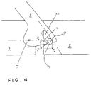
- Fig. 4 shows the operation of a known lever of this kind.
- the lever is pivotally connected by way of a pivot pin 7 to a first plug part 1.
- the slideway 10 engages around a sliding member 4 of the second plug part 2 and contacts the same at a place P.
- the two connector parts are movable relatively to one another in the plugging direction which corresponds to the direction of the connection between the pivot pin 7 and the sliding member 4.
- the slideway 10 forms an angle ⁇ with the plugging direction at the place P.
- the force F applied by the slideway perpendicularly to the sliding member 4 can be broken down into an operative component F ⁇ parallel to the direction of movement and a component F perpendicular to the first-mentioned component. These two components are proportional to cos ⁇ and sin ⁇ respectively.
- the lever of the connector arrangement according to the invention has no fixed pivot pin. Instead, two slideways are provided engaging one each with the respective sliding member of the first casing part and second casing part.
- the two slideways of such a construction have the same rise as in Fig. 4 relatively to a common centre of rotation, it will be readily apparent that for a given angle of rotation the movement of the casing parts of the arrangement relatively to one another in an arrangement according to the invention is twice that of the conventional arrangement.
- the rises of the slideways have remained the same the percentage distribution of the forces between operative forces parallel to the plugging movement and unwanted forces perpendicular thereto are the same as in the conventional arrangement.
- the rise of the slideways of a connector arrangement according to the invention need be only half as much as in a conventional example so that the distribution of the applied force to the effective force and the unwanted force is improved - i.e., the lever is easier to operate. Mechanical stressing is therefore reduced and so the complete connector arrangement can be of lighter construction.
- the centre of rotation of the lever is defined by a pivot pin guided in guide means which are preferably in the form of an elongate slot oriented in the plugging direction of the arrangement.
- the arrangement according to the invention can comprise a number of groups of contacts and a number of levers.
- the groups of contacts can be, for example, conventional connectors which can be combined to form an arrangement by a clip or in the wall of an appliance.
- the or each guide means and the or each lever can be disposed on the clip and the first sliding member can be disposed on such wall.
- two plug-in connectors can be disposed on both sides of the lever or associated guide means so as to be movable into contact by operation of just one lever.
- Groups of contacts can be disposed between two levers.
- the guide means are side walls of the first casing part into which the second casing part is plugged.
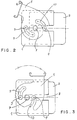
- Fig. 1 is a view in side elevation of a contact casing 1, the matching element 2 to be plugged into the casing 1, both of them having sliding members 3, 4 in the form of cylindrical parts which project laterally in the viewing direction, and a lever 5 for drawing the two casing parts 1, 2 together.
- a web 6 which extends in the viewing direction of Fig. 1 the lever 5 shown is connected to a congruent second lever behind it, the latter lever not being visible in Fig. 1.
- the web 6 and the two levers 5 form a U-shaped member which can engage around the contact casing 1 on two sides, the pivot pins 7 of the levers engaging in corresponding slots 8 in the casing 1.
- the pivot pins 7 have a stem part whose diameter and length correspond substantially to the width of the slot 8 and the wall thickness of the casing 1 at the edge of the slot 8 respectively, and a head part which is of greater diameter and which moves inside the casing 1 and prevents the pivot pin 7 from escaping axially when stressed.
- Each lever 5 has two slideways 9, 10 in the form of spiral grooves disposed diametrically opposite one another on either side of the pivot pin 7.
- One, 9, of the slideways is closed peripherally and is adapted to receive a projection 3 disposed on casing 1 in prolongation of the slot 8.
- the pins 7 are introduced into the slots 8 until the projections 3 first force the edge zones 11 of the levers 5 away from the casing 1 resiliently and finally engage in the closed slideways 9.
- each lever 5 can have near the slideway 9 a chamfer or slight outward bend.
- the second open slideway 10 is adapted to receive the projection 4 of the companion element 2.
- the companion member 2 can be introduced freely into the casing 1 until the projections 4 which extend through the slots 8 abut the inside of the slideways 9. This state is shown in Fig. 2.
- the lever 5 is turned clockwise around the pin 7. During the rotation the pin 7 engages to an increasing depth in the slot 8 so that the centre of rotation is displaced continuously in the plugging direction.
- the projections 3 In the position shown in Fig. 3 the pivot 7, the projections 3 have reached the end of their paths and the contact is in the closed state.
- the two casing parts 1, 2 cannot be separated from one another in this position unless the lever is turned again or destroyed.
- Known latching means can be provided to latch the lever 5 in the closed position.
- the slideways shown in Figs. 1 - 3 have the shape of archimedean spirals.
- the rise of archimedean spirals is independent of the angle of rotation so that this shape is particularly suitable if the plug-in resistance of the casing parts is operative substantially over the complete relative travel of the lever.
- the plug-in resistance may be particularly great in places, for instance, when the contact pins of the connector start to enter the associated bushes. In order that this increased resistance may be readily overcome it may be convenient to combine the shape of the slideways, for example, on a number of archimedean spiral sub-elements having different rises, the rise chosen being less according as the resistance to be overcome is greater in order to even out the force required to close the lever and therefore, the mechanical stressing of the connector.
Landscapes
- Details Of Connecting Devices For Male And Female Coupling (AREA)
Abstract
The invention relates to a connector arrangement which is secured by a pivoting lever (5). The lever (5), which is movable towards the two casing parts (1, 2) of the arrangement has two slideways (9, 10) engageable with sliding members (3, 4) rigidly secured to the casing parts (1, 2).
Description
- This invention relates to a connector arrangement having at least two interconnectable casing parts and a lever which facilitates an electrical contact between the casing parts against the possibly substantial plug-in resistance and which if required locks the plugged-in casing parts in their plugged-in position.
- A connector arrangement according to the preamble of
claim 1 is known from WO 94/14212. - The range of rotation of the lever of such an arrangement is usually limited to an angle of the order of 90°. This feature limits the length of the plug-in path in which the lever can assist the plug-in movement, as will become clear hereinafter.
- The shape of the slideway can be described in a polar co-ordinates system centred on the pivot pin as function R (φ) of the azimuth angle φ. The term "rise of the slideway" is to be understood as denoting the differentiation dR/dφ from the azimuth angle.
- Fig. 4 shows the operation of a known lever of this kind. The lever is pivotally connected by way of a
pivot pin 7 to afirst plug part 1. Theslideway 10 engages around a slidingmember 4 of thesecond plug part 2 and contacts the same at a place P. The two connector parts are movable relatively to one another in the plugging direction which corresponds to the direction of the connection between thepivot pin 7 and the slidingmember 4. Theslideway 10 forms an angle α with the plugging direction at the place P. The force F applied by the slideway perpendicularly to the slidingmember 4 can be broken down into an operative component F∥ parallel to the direction of movement and a component F perpendicular to the first-mentioned component. These two components are proportional to cos α and sin α respectively.
 - Since there is a limit to the angle of rotation of the lever, the rise of the slideway and, correspondingly, the angle α must be increased if it is required to lengthen the plugging path. However, as will be readily apparent the operative component of the force decreases as the angle α increases and the component perpendicular to the plugging direction, which produces only unwanted friction, increases. Consequently, a lever of this kind can assist the plug-in movement only when the plugging distance is short.
- It is therefore the object of the invention to provide a connector arrangement having a lever which can boost the plug-in movement over relatively long distances.
- The features of
claim 1 solve this problem. Dependent claims are directed to preferred embodiments of the invention. - In contrast to Fig. 4, the lever of the connector arrangement according to the invention has no fixed pivot pin. Instead, two slideways are provided engaging one each with the respective sliding member of the first casing part and second casing part. When the two slideways of such a construction have the same rise as in Fig. 4 relatively to a common centre of rotation, it will be readily apparent that for a given angle of rotation the movement of the casing parts of the arrangement relatively to one another in an arrangement according to the invention is twice that of the conventional arrangement. However, since the rises of the slideways have remained the same the percentage distribution of the forces between operative forces parallel to the plugging movement and unwanted forces perpendicular thereto are the same as in the conventional arrangement. On the other hand, and as will be readily apparent, for a given plugging distance the rise of the slideways of a connector arrangement according to the invention need be only half as much as in a conventional example so that the distribution of the applied force to the effective force and the unwanted force is improved - i.e., the lever is easier to operate. Mechanical stressing is therefore reduced and so the complete connector arrangement can be of lighter construction.
- Preferably, the centre of rotation of the lever is defined by a pivot pin guided in guide means which are preferably in the form of an elongate slot oriented in the plugging direction of the arrangement.
- Basically the arrangement according to the invention can comprise a number of groups of contacts and a number of levers. The groups of contacts can be, for example, conventional connectors which can be combined to form an arrangement by a clip or in the wall of an appliance. In such cases the or each guide means and the or each lever can be disposed on the clip and the first sliding member can be disposed on such wall.
- Also, for example, two plug-in connectors can be disposed on both sides of the lever or associated guide means so as to be movable into contact by operation of just one lever. Groups of contacts can be disposed between two levers. Very advantageously in this case the guide means are side walls of the first casing part into which the second casing part is plugged.
- Other features and advantages will become apparent from the description of an embodiment of the invention with reference to the drawings wherein:
- Fig. 1 shows the parts of a connector arrangement according to the invention;
- Fig. 2 shows the arrangement of Fig. 1 with the lever open;
- Fig. 3 shows the arrangement of Fig. 1 with the lever closed, and
- Fig. 4 shows the operation of a known connector arrangement.
- Fig. 1 is a view in side elevation of a
contact casing 1, thematching element 2 to be plugged into thecasing 1, both of them having slidingmembers lever 5 for drawing the twocasing parts web 6 which extends in the viewing direction of Fig. 1 thelever 5 shown is connected to a congruent second lever behind it, the latter lever not being visible in Fig. 1. Theweb 6 and the two levers 5 form a U-shaped member which can engage around thecontact casing 1 on two sides, thepivot pins 7 of the levers engaging incorresponding slots 8 in thecasing 1. Thepivot pins 7 have a stem part whose diameter and length correspond substantially to the width of theslot 8 and the wall thickness of thecasing 1 at the edge of theslot 8 respectively, and a head part which is of greater diameter and which moves inside thecasing 1 and prevents thepivot pin 7 from escaping axially when stressed. Eachlever 5 has twoslideways pivot pin 7. One, 9, of the slideways is closed peripherally and is adapted to receive aprojection 3 disposed oncasing 1 in prolongation of theslot 8. In the assembly of the connector thepins 7 are introduced into theslots 8 until theprojections 3 first force theedge zones 11 of thelevers 5 away from thecasing 1 resiliently and finally engage in the closedslideways 9. To facilitate this theouter edge zone 11 of eachlever 5 can have near the slideway 9 a chamfer or slight outward bend. The secondopen slideway 10 is adapted to receive theprojection 4 of thecompanion element 2. When thelevers 5 are in the orientation shown thecompanion member 2 can be introduced freely into thecasing 1 until theprojections 4 which extend through theslots 8 abut the inside of theslideways 9. This state is shown in Fig. 2. To close the connection thelever 5 is turned clockwise around thepin 7. During the rotation thepin 7 engages to an increasing depth in theslot 8 so that the centre of rotation is displaced continuously in the plugging direction. In the position shown in Fig. 3 thepivot 7, theprojections 3 have reached the end of their paths and the contact is in the closed state. The twocasing parts lever 5 in the closed position. - The slideways shown in Figs. 1 - 3 have the shape of archimedean spirals. The rise of archimedean spirals is independent of the angle of rotation so that this shape is particularly suitable if the plug-in resistance of the casing parts is operative substantially over the complete relative travel of the lever. The plug-in resistance may be particularly great in places, for instance, when the contact pins of the connector start to enter the associated bushes. In order that this increased resistance may be readily overcome it may be convenient to combine the shape of the slideways, for example, on a number of archimedean spiral sub-elements having different rises, the rise chosen being less according as the resistance to be overcome is greater in order to even out the force required to close the lever and therefore, the mechanical stressing of the connector.
Claims (13)
- A connector arrangement comprising:a first casing part (1) having at least one first contact;a second casing part (2) pluggable into the first casing part and having at least one second contact which is a companion contact for the or each first contact;at least one lever (5) pivotable between an open position, in which the two casing parts (1, 2) can be separated from one another, and a closed position, in which the casing parts cannot be separated from one another; anda first slideway (10) rigidly connected to the lever (5), anda first sliding member (4) which is connected to one (2) of the casing parts, can be engaged with the first slideway (10) in the open position of the lever and during rotation thereof is guided by and moved along the first slideway (10);characterised in thata second slideway (9) and a second sliding member (3) are in engagement with one another and are connected to the lever (5) and other casing part (1) respectively so that upon rotation of the lever (5) the second sliding member (4) moves along the second slideway (10).
- An arrangement according to claim 1, characterised in that the lever (5) is pivotable around a pivot pin (7).
- An arrangement according to claim 2, characterised in that guide means receiving the pivot pin (7) in an elongate slot (8) oriented in the plugging direction of the arrangement is rigidly connected to the first casing part (1).
- An arrangement according to any of claims 1 to 3, characterised in that at least one of the sliding members (3, 4) is a pin which engages in the associated slideway (9, 10), the same being in the form of a slot.
- An arrangement according to any of claims 1 to 4, characterised in that at least one of the sliding members has a pair of projections engaging around the raised associated slideway.
- An arrangement according to any of claims 1 to 5, characterised in that each of the casing parts (1, 2) engages around two contact groups disposed on both sides of the lever (5).
- An arrangement according to any of claims 1 to 5, characterised in that each casing part (1, 2) engages around a contact group disposed between two levers (5).
- An arrangement according to claim 7, characterised in that the levers are rigidly interconnected for simultaneous movement.
- An arrangement according to claim 3 and claim 7 or 8, characterised in that the guide means are side walls of the first casing part.
- An arrangement according to claim 9, characterised in that the sliding member of the second casing part (2) engages, with the lever in the closed position, with the slideway (10) through the slot (8) of the guide means.
- An arrangement according to any of claims 1 to 10, characterised in that the second slideway (9) is so shaped as not to be disengageable from its sliding member (3) by rotation of the lever (5).
- An arrangement according to any of claims 1 to 11, characterised in that the local rise of the slideways is such that the resistance of the lever to rotation is substantially independent of the plug-in resistance of the casing parts.
- An arrangement according to any of claims 1 to 12, characterised in that the local rise of the slideways is smaller according as the plug-in resistance of the casing parts is greater.
Applications Claiming Priority (2)
| Application Number | Priority Date | Filing Date | Title |
|---|---|---|---|
| DE1995108218 DE19508218A1 (en) | 1995-03-08 | 1995-03-08 | Connector arrangement with double eccentric |
| DE19508218 | 1995-03-08 |
Publications (2)
| Publication Number | Publication Date |
|---|---|
| EP0731536A2 true EP0731536A2 (en) | 1996-09-11 |
| EP0731536A3 EP0731536A3 (en) | 1997-08-06 |
Family
ID=7756030
Family Applications (1)
| Application Number | Title | Priority Date | Filing Date |
|---|---|---|---|
| EP96103066A Withdrawn EP0731536A3 (en) | 1995-03-08 | 1996-02-29 | A double eccentric connector arrangement |
Country Status (2)
| Country | Link |
|---|---|
| EP (1) | EP0731536A3 (en) |
| DE (1) | DE19508218A1 (en) |
Cited By (4)
| Publication number | Priority date | Publication date | Assignee | Title |
|---|---|---|---|---|
| FR2928040A1 (en) * | 2008-02-26 | 2009-08-28 | Peugeot Citroen Automobiles Sa | Electric connector i.e. male or female electric connector, for motor vehicle, has coupling member comprising gripping unit placed and utilized after another unit for completing its rotational drive until member is placed in locking position |
| WO2011076950A1 (en) | 2009-12-24 | 2011-06-30 | Fci Automotive Holding | Modular connector system |
| CN114256687A (en) * | 2020-09-25 | 2022-03-29 | Aptiv技术有限公司 | Electrical connector assembly with mating lever and connector position assurance member |
| EP3975346A1 (en) * | 2020-09-25 | 2022-03-30 | Aptiv Technologies Limited | Electrical connector assembly with mating lever, system comprising such assembly and method for mating such system |
Families Citing this family (4)
| Publication number | Priority date | Publication date | Assignee | Title |
|---|---|---|---|---|
| JP3987736B2 (en) * | 2002-02-26 | 2007-10-10 | 住友電装株式会社 | Lever type connector |
| DE102004053516A1 (en) * | 2004-10-29 | 2006-05-11 | Atmel Germany Gmbh | Plug-in modules of a connector for simultaneously connecting a plurality of electrical contacts |
| DE102018131378A1 (en) * | 2018-12-07 | 2020-01-09 | Lisa Dräxlmaier GmbH | CONTACTING SYSTEM FOR MAKING AN ELECTRICAL CONNECTOR |
| DE102023119847A1 (en) * | 2023-07-26 | 2025-01-30 | Amphenol-Tuchel Electronics Gesellschaft mit beschränkter Haftung | connectors with primary locking |
Family Cites Families (5)
| Publication number | Priority date | Publication date | Assignee | Title |
|---|---|---|---|---|
| GB952652A (en) * | 1961-09-08 | 1964-03-18 | Belling & Lee Ltd | Improvements in two-part connectors |
| GB952651A (en) * | 1961-09-08 | 1964-03-18 | Belling & Lee Ltd | Improvements in two part connectors |
| US4497384A (en) * | 1982-01-04 | 1985-02-05 | Smith International, Inc. | Reamer disassembly |
| JP2532620Y2 (en) * | 1991-02-28 | 1997-04-16 | 矢崎総業株式会社 | Low insertion / extraction force connector |
| US5201665A (en) * | 1991-09-24 | 1993-04-13 | Cardell Corporation | Cam lock connector |
-
1995
- 1995-03-08 DE DE1995108218 patent/DE19508218A1/en not_active Withdrawn
-
1996
- 1996-02-29 EP EP96103066A patent/EP0731536A3/en not_active Withdrawn
Cited By (6)
| Publication number | Priority date | Publication date | Assignee | Title |
|---|---|---|---|---|
| FR2928040A1 (en) * | 2008-02-26 | 2009-08-28 | Peugeot Citroen Automobiles Sa | Electric connector i.e. male or female electric connector, for motor vehicle, has coupling member comprising gripping unit placed and utilized after another unit for completing its rotational drive until member is placed in locking position |
| WO2011076950A1 (en) | 2009-12-24 | 2011-06-30 | Fci Automotive Holding | Modular connector system |
| CN114256687A (en) * | 2020-09-25 | 2022-03-29 | Aptiv技术有限公司 | Electrical connector assembly with mating lever and connector position assurance member |
| EP3975346A1 (en) * | 2020-09-25 | 2022-03-30 | Aptiv Technologies Limited | Electrical connector assembly with mating lever, system comprising such assembly and method for mating such system |
| EP3975347A1 (en) * | 2020-09-25 | 2022-03-30 | Aptiv Technologies Limited | Electrical connector assembly with mating lever and cpa |
| US11757230B2 (en) | 2020-09-25 | 2023-09-12 | Aptiv Technologies Limited | Electrical connector assembly with mating lever and CPA |
Also Published As
| Publication number | Publication date |
|---|---|
| DE19508218A1 (en) | 1996-09-12 |
| EP0731536A3 (en) | 1997-08-06 |
Similar Documents
| Publication | Publication Date | Title |
|---|---|---|
| US6213795B1 (en) | Two-part electrical connector | |
| EP0938162B1 (en) | Two-part electrical connector | |
| US5681184A (en) | Connector with secondary locking and coupling mechanisms | |
| KR960030488A (en) | Electrical connector assembly with improved cam device | |
| US5899762A (en) | Electrical connector having an insertion and extraction slide | |
| KR101792090B1 (en) | High-current plug-in connector | |
| US6893288B2 (en) | Electrical connector for a flat cable | |
| EP0808749A2 (en) | Connector for airbag gas generator | |
| US5830000A (en) | Locking lever connector mechanism | |
| GB2260659A (en) | Lever for operating an electrical connector | |
| US20150147917A1 (en) | Connector and mating connector | |
| JPH11510641A (en) | Electrical terminal | |
| JPH04218281A (en) | Electric connector | |
| EP0579428B1 (en) | Lever type connector | |
| WO1998005097A1 (en) | Latching system | |
| US5647752A (en) | Lever-type connector | |
| KR101063115B1 (en) | Electrical connector element | |
| US10950967B2 (en) | Electric terminal housing with a terminal lock | |
| EP0991144A2 (en) | An electrical connector with a transport device | |
| US5545047A (en) | Connector | |
| KR102937504B1 (en) | Plug connector with optional unlocking | |
| CN117913585A (en) | Electrical connection device with pivotable actuating element | |
| US6129567A (en) | Connector assembly having an actuating slide | |
| CN118715674A (en) | Plug connector | |
| KR100995279B1 (en) | Lever Type Connector Assembly |
Legal Events
| Date | Code | Title | Description |
|---|---|---|---|
| PUAI | Public reference made under article 153(3) epc to a published international application that has entered the european phase |
Free format text: ORIGINAL CODE: 0009012 |
|
| AK | Designated contracting states |
Kind code of ref document: A2 Designated state(s): AT BE ES FR GB IT NL SE |
|
| PUAL | Search report despatched |
Free format text: ORIGINAL CODE: 0009013 |
|
| AK | Designated contracting states |
Kind code of ref document: A3 Designated state(s): AT BE ES FR GB IT NL SE |
|
| 17P | Request for examination filed |
Effective date: 19970722 |
|
| STAA | Information on the status of an ep patent application or granted ep patent |
Free format text: STATUS: THE APPLICATION HAS BEEN WITHDRAWN |
|
| 18W | Application withdrawn |
Withdrawal date: 20000126 |