EP0731359B1 - AC load control device having a graphical display - Google Patents
AC load control device having a graphical display Download PDFInfo
- Publication number
- EP0731359B1 EP0731359B1 EP96101138A EP96101138A EP0731359B1 EP 0731359 B1 EP0731359 B1 EP 0731359B1 EP 96101138 A EP96101138 A EP 96101138A EP 96101138 A EP96101138 A EP 96101138A EP 0731359 B1 EP0731359 B1 EP 0731359B1
- Authority
- EP
- European Patent Office
- Prior art keywords
- display
- load
- metering
- signals
- menu
- Prior art date
- Legal status (The legal status is an assumption and is not a legal conclusion. Google has not performed a legal analysis and makes no representation as to the accuracy of the status listed.)
- Expired - Lifetime
Links
- 230000001681 protective effect Effects 0.000 claims description 20
- 238000012544 monitoring process Methods 0.000 claims description 6
- 238000012545 processing Methods 0.000 claims description 3
- 230000006854 communication Effects 0.000 description 9
- 238000004891 communication Methods 0.000 description 9
- 230000006870 function Effects 0.000 description 7
- 238000012360 testing method Methods 0.000 description 4
- 230000007935 neutral effect Effects 0.000 description 3
- 238000003825 pressing Methods 0.000 description 3
- 239000004020 conductor Substances 0.000 description 2
- 230000008901 benefit Effects 0.000 description 1
- 230000007175 bidirectional communication Effects 0.000 description 1
- 230000008859 change Effects 0.000 description 1
- 230000003247 decreasing effect Effects 0.000 description 1
- 230000001934 delay Effects 0.000 description 1
- 238000010586 diagram Methods 0.000 description 1
- 230000008030 elimination Effects 0.000 description 1
- 238000003379 elimination reaction Methods 0.000 description 1
- 230000007613 environmental effect Effects 0.000 description 1
- 239000004973 liquid crystal related substance Substances 0.000 description 1
- 238000012423 maintenance Methods 0.000 description 1
- 238000004519 manufacturing process Methods 0.000 description 1
- 230000007246 mechanism Effects 0.000 description 1
- 238000000034 method Methods 0.000 description 1
- 230000008569 process Effects 0.000 description 1
- 230000009993 protective function Effects 0.000 description 1
Images

Classifications
-
- H—ELECTRICITY
- H02—GENERATION; CONVERSION OR DISTRIBUTION OF ELECTRIC POWER
- H02H—EMERGENCY PROTECTIVE CIRCUIT ARRANGEMENTS
- H02H3/00—Emergency protective circuit arrangements for automatic disconnection directly responsive to an undesired change from normal electric working condition with or without subsequent reconnection ; integrated protection
-
- G—PHYSICS
- G01—MEASURING; TESTING
- G01R—MEASURING ELECTRIC VARIABLES; MEASURING MAGNETIC VARIABLES
- G01R19/00—Arrangements for measuring currents or voltages or for indicating presence or sign thereof
- G01R19/25—Arrangements for measuring currents or voltages or for indicating presence or sign thereof using digital measurement techniques
- G01R19/2513—Arrangements for monitoring electric power systems, e.g. power lines or loads; Logging
-
- G—PHYSICS
- G01—MEASURING; TESTING
- G01R—MEASURING ELECTRIC VARIABLES; MEASURING MAGNETIC VARIABLES
- G01R22/00—Arrangements for measuring time integral of electric power or current, e.g. electricity meters
-
- H—ELECTRICITY
- H02—GENERATION; CONVERSION OR DISTRIBUTION OF ELECTRIC POWER
- H02B—BOARDS, SUBSTATIONS OR SWITCHING ARRANGEMENTS FOR THE SUPPLY OR DISTRIBUTION OF ELECTRIC POWER
- H02B1/00—Frameworks, boards, panels, desks, casings; Details of substations or switching arrangements
- H02B1/015—Boards, panels, desks; Parts thereof or accessories therefor
- H02B1/03—Boards, panels, desks; Parts thereof or accessories therefor for energy meters
-
- H—ELECTRICITY
- H02—GENERATION; CONVERSION OR DISTRIBUTION OF ELECTRIC POWER
- H02B—BOARDS, SUBSTATIONS OR SWITCHING ARRANGEMENTS FOR THE SUPPLY OR DISTRIBUTION OF ELECTRIC POWER
- H02B15/00—Supervisory desks or panels for centralised control or display
-
- H—ELECTRICITY
- H02—GENERATION; CONVERSION OR DISTRIBUTION OF ELECTRIC POWER
- H02H—EMERGENCY PROTECTIVE CIRCUIT ARRANGEMENTS
- H02H3/00—Emergency protective circuit arrangements for automatic disconnection directly responsive to an undesired change from normal electric working condition with or without subsequent reconnection ; integrated protection
- H02H3/02—Details
- H02H3/04—Details with warning or supervision in addition to disconnection, e.g. for indicating that protective apparatus has functioned
-
- G—PHYSICS
- G01—MEASURING; TESTING
- G01R—MEASURING ELECTRIC VARIABLES; MEASURING MAGNETIC VARIABLES
- G01R19/00—Arrangements for measuring currents or voltages or for indicating presence or sign thereof
- G01R19/25—Arrangements for measuring currents or voltages or for indicating presence or sign thereof using digital measurement techniques
-
- G—PHYSICS
- G01—MEASURING; TESTING
- G01R—MEASURING ELECTRIC VARIABLES; MEASURING MAGNETIC VARIABLES
- G01R21/00—Arrangements for measuring electric power or power factor
- G01R21/133—Arrangements for measuring electric power or power factor by using digital technique
-
- H—ELECTRICITY
- H01—ELECTRIC ELEMENTS
- H01H—ELECTRIC SWITCHES; RELAYS; SELECTORS; EMERGENCY PROTECTIVE DEVICES
- H01H71/00—Details of the protective switches or relays covered by groups H01H73/00 - H01H83/00
- H01H2071/006—Provisions for user interfaces for electrical protection devices
Definitions
- This invention relates, generally, to an AC load control device having a graphical display device for graphically displaying a plurality of parameters of the AC electrical load usage.
- US-5,220,479 discloses an AC load control device as specified in the preamble of claim 1, comprising an electronic trip device whose front panel is formed by a flat screen display and controlled by a microprocessor.
- the front panel is arranged in such a way as to be seen by a user and displays information relating to tripping parameters such as threshold and time delays. This information is represented by a combination of alphanumeric signs and analog type diagrams.
- the front panel of US-5,220,479 does not comprise any switches on keys enabling tripping parameters to be modified or selecting the type and format of information to be displayed on the front panel.
- an object of the present invention to produce an AC load control device which allows the user to select the types of information and the format in which said information is displayed on the display means.
- the AC load control device comprises: a circuit protective device for interrupting electrical power to a load; means for monitoring AC electrical load usage of the load including a first means for controlling said circuit protective device and a second means for producing a plurality of signals representative of at least one of the current, voltage and power related characteristics of the load; and a graphical display device connected to said device for monitoring AC electrical load usage and adapted so as to graphically display a plurality of parameters of the AC electrical load usage of the load simultaneously, said graphical display device including: metering means connected to said second means for receiving and processing and storing said plurality of signals and for producing graphics related output image signals; and display means disposed on a panel of the AC load control device, connected to said metering means and adapted to receive said graphic related output image signals for producing graphic images which are simultaneously viewable by a user; characterised in that the graphical display device further includes: menu means for displaying a plurality of different images on said display means, each of said different images representing at least one parameter of the AC electrical load usage; menu
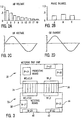
- the front panel 10 of the present invention indicating exemplary information or indicia.
- the front panel 10 has disposed thereon a liquid crystal diode (LCD) display 12, a key-pad input area 14, status indicators 16, 18, 20, 22, and 24 indicating system status, alarm tripping, system check, protective metering, and communications check respectively.
- LCD liquid crystal diode
- a communication port 26 as well as a test connector 28.
- phase A display area 13 Shown on LCD display 12 are phase A display area 13, phase B display area 15, phase C display area 17 and phase N display area 19. It is to be understood that although in the preferred embodiment of the present invention the front panel 10 has numerous functions in a particular order, different indicators or layout may be utilized.
- LCD display 12 shows four separate display areas 13, 15, 17 and 19, the number of display areas may be increased or decreased as appropriate as well as the use or elimination of numerical indicia thereunder.
- LCD display 12 is at least a 128 by 128 pixel display although other sizes may be utilized as well as the use of color and the like. Further, the LCD display 12 could be electrofluorescent or any other type of suitable display.
- the front panel 10 of the present invention and hence the graphic display taught by the preferred embodiment of the present invention cooperates with an electronic trip unit typically utilized with and part of a circuit breaker.
- Such trip units frequently referred to as metering trip units, are readily known and available to one skilled in the art and utilize current transformers and electronic circuitry to measure and if necessary calculate a multitude of parameters relating to power being consumed by the load to which they are attached. Accordingly, a more detailed description will not be given.
- keypad input 14 is utilized to program and/or command the information to be presented by LCD display 12.
- communication port 26 which in the preferred embodiment of the present invention presents an RS-232 protocol scheme, may be utilized to perform bi-directional communications to accomplish this and other functions as described below. However, it is to be understood that other types of ports may be utilized.
- test connector 28 is utilized to perform interrogation and testing of panel 10 as well as the breaker (not shown) to which it is attached, the connector may be eliminated or modified as appropriate.
- a protective board such as 30, which may be functionally part of a metering trip unit, is used to cooperate directly with a circuit breaker, protective relay and the like (not shown).
- protective board 30 cooperates with a circuit breaker (not shown) and performs housekeeping and monitoring functions such as tripping of the breaker, measuring load values and the like.
- a typical circuit breaker is an 'SB' type circuit breaker manufactured and produced by Siemens Energy & Automation of Atlanta, Georgia although other manufacturers equipment could and may be utilized.
- the metering board 32 which is interconnected through wire interconnects 34, 36 with protective board 30 is utilized to process, accumulate and otherwise monitor the power being consumed by the load (not shown), for eventual display by LCD display 12.
- the metering board 32 has interconnected therewith a plurality of components necessary to operate the control panel 10 and hence the display 12 of the present invention.
- Jack M-J1 at designated numeral 38 functions as the communication port jack which is ultimately connected to communication port 26 as shown in Figure 1.
- Jack M-J4 which is designated numeral 40 cooperates with and is connected to test connector 28 as also shown in Figure 1.
- terminal M-J2, designated numeral 42 functions as a keypad input jack and cooperates with the keypad 14 as shown in Figure 1 while Jack M-J3, designated numeral 44 cooperates directly with the actual LCD display 12 as shown in Figure 1.
- a typical protective board for the mentioned 'SB' circuit breaker utilizes a microprocessor such as, for example, a 68HC11 which has an integral 8 bit A to D converter and which is suitable for the monitoring, housekeeping and protective functions previously mentioned.
- a microprocessor such as, for example, a 68HC11 which has an integral 8 bit A to D converter and which is suitable for the monitoring, housekeeping and protective functions previously mentioned.
- the metering board 32 has an external 12 bit A to D converter which thereafter is interconnected with preferably a 68HC16 microprocessor which is a 16 bit microprocessor.
- graphic LCD display 12 may be sufficiently detailed so as to provide accurate, smooth and useful graphics based graphical and alphanumeric information on display 12.
- Figures 2a, 2b, 2c and 2d indicate exemplary graphical information which may be displayed by LCD display 12. Accordingly such types of information may include but are not limited to harmonics amongst any of the conductors, phase balance between the three phases, voltage on any of the three phases as well as current among the three phases and of course the neutral conductor parameters may also be viewed.
- LCD display 12 Operation and implementation of LCD display 12 is relatively simple and will now be described. Although, other types of keypads such as, for example, alphanumeric may be utilized, in the preferred embodiment of the present invention a simple six button keypad input such as 14 having Up, Down, Left, Right, Escape and Enter keys is sufficient.
- keypad input 14 cooperates with the mentioned 68HC16 microprocessor (not shown) contained on metering board 32 and functions in conjunction with software so as to provide a menu style operation for LCD display 12.
- the LCD display 12 is capable of operating in a "pure" graphics mode thereby allowing access to each individual pixel, in the preferred embodiment of the present invention, rather than having a microprocessor update each pixel during a write command thereby creating a "clunky” or “jagged” screen update, a separate RAM is used.
- a RAM in conjunction with a microprocessor and hence as a buffer area for the LCD display, individual bit manipulations are allowed and done in RAM rather than individual LCD pixel manipulations at the display. This has the advantage of allowing the RAM to be periodically “dumped" to the LCD in a block and thereby making the screen update appear much more smooth. This is found to be much more desireable and convenient from the users standpoint when the user "toggles" between menus or information on the display.
- graphical display in the present invention, it is specifically meant to mean and include graphics as is presently used and understood in the industry, that is the ability to display information in an 'analog' fashion, and not merely the use of a 'graphics' display capable of only showing alphanumeric characters.
- menus which may be created, maintained or prestored.
- Menus in the preferred embodiment of the present invention also include housekeeping items such as contrast adjustment for the LCD display. This is accomplished simply by having the appropriate menu appear on the screen and using the Up or Down keys to adjust the contrast. It has been found that adjustable contrast is a necessary and important feature due to the great variety of lighting environments in which equipment of the present invention is installed.
- a Sign-On screen will display housekeeping items such as the version number of the software, copyright notices, logos and the like. Thereafter, when any key is pressed the highest level menu choices available will be displayed. These choices are from a category standpoint, Protective, Metering, Communications and Logs.
- the Protective menu has selections for the long time, instantaneous, short-time and ground fault settings.
- the Metering menu has selections for metered data, alarms, protective relays, and demand period.
- the Communications menu has selections for EIA-485 settings as well as EIA-232 settings.
- the Logs menu has selections for the min-max metering log, the trip log, as well as clearing the min-max log and clearing the trip log.
- the metering/metered data menu has selections for the meter screen and graphs while the metering/alarms menu has selections for all the metering alarm settings. Similarly, the metering/protective relay menu has selections for all the metering protective relay settings.
- the metering/metered data/meter screen will display all the metered data on a single screen in text form while the metering/metered data/graphs menu will have selections to display graphs for items such as total harmonics, phase current loading and balance, phase A, B and C voltage waveforms and phase A, B and C current waveforms (see e.g. Figures 2A-2D).
- the Logs/trip log screen displays the most recent trip event as well as at least two trip events prior to the most recent event also recalled. Additionally, the log/min-max metering log displays a menu of all metered values. Therefore, when a value is selected, LCD display 12 will produce a screen showing the values min-max with time stamps adjacent thereto. By pressing the up or down keys as appropriate sequential values will be displayed on the screen.
- menu items may therefore be produced and simply by pressing the Enter key certain groups contained in the menu may be selected as well as use of the appropriate directional keys to toggle through the various menus displayed. Therefore, other than during start-up as described above, the arrow keys will highlight the category/graph/menu which may be selected. Thereafter, by pressing the Enter key, a particular menu selection will show the sub-menu items or display of an actual graph or data.
- the menu outline is provided in a hierarchical format as shown below, although this may be changed as required.
- Metered Data Meter Screen Graphs Total Harmonics Phase Current Loading & Balance Phase A Voltage Waveform Phase B Voltage Waveform Phase C Voltage Waveform Phase A Current Waveform Phase B Current Waveform Phase C Current Waveform Alarms Over Current Settings Ground Over Current Settings Over Amp Demand Settings Total Harmonics Settings Over KW Settings Over KW Demand Settings Over KVAR Settings Over KVA Settings Under Power Factor Lagging Settings Over Power Factor Leading Settings Protective Relays Neutral Over Current Settings Current Unbalance Settings Under Voltage Settings Voltage Unbalance Settings Over Voltage Settings Over Reverse KW Settings Under Frequency Settings Over Frequency Settings Demand Period
- Min-Max Metering Log Over Current Min-Max Ground Over Current Min-Max Over Amp Demand Min-Max Total Harmonics Min-Max Over KW Min-Max Over KW Demand Min-Max Over KVAR Min-Max Over KVA Min-Max Under Power Factor Lagging Min-Max Over Power Factor Leading Min-Max Neutral Over Current Min-Max Current Unbalance Min-Max Under Voltage Min-Max Voltage Unbalance Min-Max Over Voltage Min-Max Over Reverse KW Min-Max Under Frequency Min-Max Over Frequency Min-Max Trip Log Clear Min-Max Log Clear Trip Log
- communications may be accomplished directly so that information indicating fault readings and the like may be downloaded while the menus available to the user may be modified as appropriate.
- the present invention produces a electronic circuit protection device having an integral graphical function which provides readily accessible and useful graphical information along with a convenient mechanism to view or alter that which is seen.
Landscapes
- Engineering & Computer Science (AREA)
- Power Engineering (AREA)
- Physics & Mathematics (AREA)
- General Physics & Mathematics (AREA)
- Remote Monitoring And Control Of Power-Distribution Networks (AREA)
- Measurement Of Current Or Voltage (AREA)
- Controls And Circuits For Display Device (AREA)
Description
- This invention relates, generally, to an AC load control device having a graphical display device for graphically displaying a plurality of parameters of the AC electrical load usage.
- It is becoming increasingly important that the consumption of electrical power by a load be monitored. The reason for such importance relates to cost of operation, maintenance and keeping equipment on-line for purposes such as production, environmental controls and the like. As such, equipment manufacturers are now routinely supplying or incorporating electronic circuit protection devices thereby forming circuit breaker electronic trip units. These electronic circuit protection devices typically incorporate or have the ability to sample waveforms representative of current, voltage, power factor, harmonics, kilowatt hours, var-hours, va-hours, instantaneous power, phase balance/imbalance, phase loading in relation to historical numbers as well as a percentage of maximum level. Moreover, these values can be stored in order to form an historical database which may also include fault data, etc.
- Unfortunately, such information is generally only available in alpha-numeric displays which are viewed at the power meter or electronic trip unit. Any other form of display may only be accomplished by down loading the relevant data to another computer either directly or in a network configuration.
- Accordingly, it is difficult for an operator to quickly evaluate system performance. It is for this reason that electronic automotive dash boards typically use display graphics information in an analog gauge type format rather than an alphanumeric display. It is known and appreciated that it is quicker and easier to gauge values, performance and the like in a graphics format.
- US-5,220,479 discloses an AC load control device as specified in the preamble of claim 1, comprising an electronic trip device whose front panel is formed by a flat screen display and controlled by a microprocessor. The front panel is arranged in such a way as to be seen by a user and displays information relating to tripping parameters such as threshold and time delays. This information is represented by a combination of alphanumeric signs and analog type diagrams. However, the front panel of US-5,220,479 does not comprise any switches on keys enabling tripping parameters to be modified or selecting the type and format of information to be displayed on the front panel.
- Accordingly, it is an object of the present invention to produce an AC load control device which allows the user to select the types of information and the format in which said information is displayed on the display means.
- According to the present invention, the AC load control device comprises: a circuit protective device for interrupting electrical power to a load; means for monitoring AC electrical load usage of the load including a first means for controlling said circuit protective device and a second means for producing a plurality of signals representative of at least one of the current, voltage and power related characteristics of the load; and a graphical display device connected to said device for monitoring AC electrical load usage and adapted so as to graphically display a plurality of parameters of the AC electrical load usage of the load simultaneously, said graphical display device including: metering means connected to said second means for receiving and processing and storing said plurality of signals and for producing graphics related output image signals; and display means disposed on a panel of the AC load control device, connected to said metering means and adapted to receive said graphic related output image signals for producing graphic images which are simultaneously viewable by a user; characterised in that the graphical display device further includes: menu means for displaying a plurality of different images on said display means, each of said different images representing at least one parameter of the AC electrical load usage; menu selection means disposed on said panel for selecting one of said plurality of images so as to cause the display means to graphically present a selected image representing at least one parameter of the AC electrical load usage associated therewith.
- Reference may be now had to the accompanying figures, in which:
- Fig. 1 is a front view of the display and keypad input as well as the graphical display of the present invention;
- Figs. 2a, 2b, 2c, 2d are representative of graphs shown on the display of the present invention; and
- Fig. 3 is an overview of a circuit breaker display inter-connect scheme of the preferred embodiment of the present invention.
-
- Referring now to Figure 1 there is shown the
front panel 10 of the present invention indicating exemplary information or indicia. As can be seen, thefront panel 10 has disposed thereon a liquid crystal diode (LCD)display 12, a key-pad input area 14,status indicators communication port 26 as well as atest connector 28. - Shown on
LCD display 12 are phaseA display area 13, phaseB display area 15, phaseC display area 17 and phaseN display area 19. It is to be understood that although in the preferred embodiment of the present invention thefront panel 10 has numerous functions in a particular order, different indicators or layout may be utilized. - In this regard, although
LCD display 12 shows fourseparate display areas - In the preferred embodiment of the present invention,
LCD display 12 is at least a 128 by 128 pixel display although other sizes may be utilized as well as the use of color and the like. Further, theLCD display 12 could be electrofluorescent or any other type of suitable display. - It is to be understood that the
front panel 10 of the present invention and hence the graphic display taught by the preferred embodiment of the present invention cooperates with an electronic trip unit typically utilized with and part of a circuit breaker. Such trip units, frequently referred to as metering trip units, are readily known and available to one skilled in the art and utilize current transformers and electronic circuitry to measure and if necessary calculate a multitude of parameters relating to power being consumed by the load to which they are attached. Accordingly, a more detailed description will not be given. - As described more fully below,
keypad input 14 is utilized to program and/or command the information to be presented byLCD display 12. Moreover,communication port 26, which in the preferred embodiment of the present invention presents an RS-232 protocol scheme, may be utilized to perform bi-directional communications to accomplish this and other functions as described below. However, it is to be understood that other types of ports may be utilized. - Similarly, while
test connector 28 is utilized to perform interrogation and testing ofpanel 10 as well as the breaker (not shown) to which it is attached, the connector may be eliminated or modified as appropriate. - Referring now to Figure 3 it can be seen how the display of the present invention is interconnected with the metering and protective boards of the present invention. As is readily known and available to one skilled in the art, a protective board such as 30, which may be functionally part of a metering trip unit, is used to cooperate directly with a circuit breaker, protective relay and the like (not shown). In the preferred embodiment of the present invention
protective board 30 cooperates with a circuit breaker (not shown) and performs housekeeping and monitoring functions such as tripping of the breaker, measuring load values and the like. Further, in the preferred embodiment of the present invention a typical circuit breaker is an 'SB' type circuit breaker manufactured and produced by Siemens Energy & Automation of Atlanta, Georgia although other manufacturers equipment could and may be utilized. - The
metering board 32 which is interconnected throughwire interconnects protective board 30 is utilized to process, accumulate and otherwise monitor the power being consumed by the load (not shown), for eventual display byLCD display 12. As can be seen, themetering board 32 has interconnected therewith a plurality of components necessary to operate thecontrol panel 10 and hence thedisplay 12 of the present invention. Accordingly, Jack M-J1 at designatednumeral 38 functions as the communication port jack which is ultimately connected tocommunication port 26 as shown in Figure 1. Jack M-J4 which is designatednumeral 40 cooperates with and is connected totest connector 28 as also shown in Figure 1. Similarly, terminal M-J2, designatednumeral 42 functions as a keypad input jack and cooperates with thekeypad 14 as shown in Figure 1 while Jack M-J3, designatednumeral 44 cooperates directly with theactual LCD display 12 as shown in Figure 1. - A typical protective board for the mentioned 'SB' circuit breaker utilizes a microprocessor such as, for example, a 68HC11 which has an integral 8 bit A to D converter and which is suitable for the monitoring, housekeeping and protective functions previously mentioned. However, it has been found that when trying to display information in graphical form, the resolution offered by an 8 bit A to D converter is somewhat lacking. Accordingly, in the preferred embodiment of the present invention, the
metering board 32 has an external 12 bit A to D converter which thereafter is interconnected with preferably a 68HC16 microprocessor which is a 16 bit microprocessor. - Therefore, with the use of an external 12 bit A to D converter and a 16 bit microprocessor (not shown) the information presented by
graphic LCD display 12 may be sufficiently detailed so as to provide accurate, smooth and useful graphics based graphical and alphanumeric information ondisplay 12. - Reference may be now had to Figures 2a, 2b, 2c and 2d which indicate exemplary graphical information which may be displayed by
LCD display 12. Accordingly such types of information may include but are not limited to harmonics amongst any of the conductors, phase balance between the three phases, voltage on any of the three phases as well as current among the three phases and of course the neutral conductor parameters may also be viewed. - Operation and implementation of
LCD display 12 is relatively simple and will now be described. Although, other types of keypads such as, for example, alphanumeric may be utilized, in the preferred embodiment of the present invention a simple six button keypad input such as 14 having Up, Down, Left, Right, Escape and Enter keys is sufficient. In this regard,keypad input 14 cooperates with the mentioned 68HC16 microprocessor (not shown) contained onmetering board 32 and functions in conjunction with software so as to provide a menu style operation forLCD display 12. - Although the
LCD display 12 is capable of operating in a "pure" graphics mode thereby allowing access to each individual pixel, in the preferred embodiment of the present invention, rather than having a microprocessor update each pixel during a write command thereby creating a "clunky" or "jagged" screen update, a separate RAM is used. By using a RAM in conjunction with a microprocessor and hence as a buffer area for the LCD display, individual bit manipulations are allowed and done in RAM rather than individual LCD pixel manipulations at the display. This has the advantage of allowing the RAM to be periodically "dumped" to the LCD in a block and thereby making the screen update appear much more smooth. This is found to be much more desireable and convenient from the users standpoint when the user "toggles" between menus or information on the display. - By use of the term "graphical" display in the present invention, it is specifically meant to mean and include graphics as is presently used and understood in the industry, that is the ability to display information in an 'analog' fashion, and not merely the use of a 'graphics' display capable of only showing alphanumeric characters.
- Further, although software is utilized to interact with
protective board 30,metering board 32 and hence display 12, it is to be understood that the writing of such software is within the purview of one skilled in the art and therefore a description of the actual code is not included herein. Moreover, the actual code would of course change depending upon the microprocessors and other hardware elements utilized. - As previously recited, the types of information and the format in which it is displayed is selectable by menus which may be created, maintained or prestored. Menus, in the preferred embodiment of the present invention also include housekeeping items such as contrast adjustment for the LCD display. This is accomplished simply by having the appropriate menu appear on the screen and using the Up or Down keys to adjust the contrast. It has been found that adjustable contrast is a necessary and important feature due to the great variety of lighting environments in which equipment of the present invention is installed.
- Upon system start-up, in the preferred embodiment of the present invention, a Sign-On screen will display housekeeping items such as the version number of the software, copyright notices, logos and the like. Thereafter, when any key is pressed the highest level menu choices available will be displayed. These choices are from a category standpoint, Protective, Metering, Communications and Logs. The Protective menu has selections for the long time, instantaneous, short-time and ground fault settings. The Metering menu has selections for metered data, alarms, protective relays, and demand period. The Communications menu has selections for EIA-485 settings as well as EIA-232 settings. The Logs menu has selections for the min-max metering log, the trip log, as well as clearing the min-max log and clearing the trip log.
- Further, the metering/metered data menu has selections for the meter screen and graphs while the metering/alarms menu has selections for all the metering alarm settings. Similarly, the metering/protective relay menu has selections for all the metering protective relay settings.
- The metering/metered data/meter screen will display all the metered data on a single screen in text form while the metering/metered data/graphs menu will have selections to display graphs for items such as total harmonics, phase current loading and balance, phase A, B and C voltage waveforms and phase A, B and C current waveforms (see e.g. Figures 2A-2D).
- The Logs/trip log screen displays the most recent trip event as well as at least two trip events prior to the most recent event also recalled. Additionally, the log/min-max metering log displays a menu of all metered values. Therefore, when a value is selected,
LCD display 12 will produce a screen showing the values min-max with time stamps adjacent thereto. By pressing the up or down keys as appropriate sequential values will be displayed on the screen. - Accordingly, a number of menu items may therefore be produced and simply by pressing the Enter key certain groups contained in the menu may be selected as well as use of the appropriate directional keys to toggle through the various menus displayed. Therefore, other than during start-up as described above, the arrow keys will highlight the category/graph/menu which may be selected. Thereafter, by pressing the Enter key, a particular menu selection will show the sub-menu items or display of an actual graph or data. In this regard, in the preferred embodiment of the present invention, the menu outline is provided in a hierarchical format as shown below, although this may be changed as required.
- Long Time Settings
Instantaneous Settings
Short Time Settings
Ground Fault Settings - Metered Data
Meter Screen
Graphs
Total Harmonics
Phase Current Loading & Balance
Phase A Voltage Waveform
Phase B Voltage Waveform
Phase C Voltage Waveform
Phase A Current Waveform
Phase B Current Waveform
Phase C Current Waveform
Alarms
Over Current Settings
Ground Over Current Settings
Over Amp Demand Settings
Total Harmonics Settings
Over KW Settings
Over KW Demand Settings
Over KVAR Settings
Over KVA Settings
Under Power Factor Lagging Settings
Over Power Factor Leading Settings
Protective Relays
Neutral Over Current Settings
Current Unbalance Settings
Under Voltage Settings
Voltage Unbalance Settings
Over Voltage Settings
Over Reverse KW Settings
Under Frequency Settings
Over Frequency Settings
Demand Period - EIA-485 settings
EIA-232 settings - Min-Max Metering Log
Over Current Min-Max
Ground Over Current Min-Max
Over Amp Demand Min-Max
Total Harmonics Min-Max
Over KW Min-Max
Over KW Demand Min-Max
Over KVAR Min-Max
Over KVA Min-Max
Under Power Factor Lagging Min-Max
Over Power Factor Leading Min-Max
Neutral Over Current Min-Max
Current Unbalance Min-Max
Under Voltage Min-Max
Voltage Unbalance Min-Max
Over Voltage Min-Max
Over Reverse KW Min-Max
Under Frequency Min-Max
Over Frequency Min-Max
Trip Log
Clear Min-Max Log
Clear Trip Log - Further, by utilization of
port 26, communications may be accomplished directly so that information indicating fault readings and the like may be downloaded while the menus available to the user may be modified as appropriate. - Accordingly, the present invention produces a electronic circuit protection device having an integral graphical function which provides readily accessible and useful graphical information along with a convenient mechanism to view or alter that which is seen.
- It is to be understood that many variations from the present invention may be practiced without departing from the scope of the present invention. Such variations may include, for example, a different set of microprocessors, memory devices and the like or the way in which the display is interconnected with a circuit protection device. Further, a cursor arrangement available on the screen may be utilized or a touch operated screen may be utilized. Additionally, screens having higher or lower resolution may be utilized as well as larger or smaller screens. Further, the menu choices may be expanded or minimized to reflect user requirements.
- Accordingly, the present invention is not to be limited by the specification but rather by the claims appended hereto.
Claims (9)
- An AC load control device, comprising:characterised in that the graphical display device further includes:a circuit protective device for interrupting electrical power to a load;means (30) for monitoring AC electrical load usage of the load including a first means for controlling said circuit protective device and a second means for producing a plurality of signals representative of at least one of the current, voltage and power related characteristics of the load; anda graphical display device connected to said device (30) for monitoring AC electrical load usage and adapted so as to graphically display a plurality of parameters of the AC electrical load usage of the load simultaneously,said graphical display device including:metering means (32) connected to said second means for receiving andprocessing and storing said plurality of signals and for producing graphics related output image signals; anddisplay means (12) disposed on a panel (10) of the AC load control device, connected to said metering means (32) and adapted to receive said graphic related output image signals for producing graphic images which are simultaneously viewable by a user;menu means for displaying a plurality of different images on said display means (12), each of said different images representing at least one parameter of the AC electrical load usage;menu selection means (14) disposed on said panel (10) for selecting one of said plurality of images so as to cause the display means(12) to graphically present a selected image representing at least one parameter of the AC electrical load usage associated therewith.
- A device according to Claim 1, wherein said menu selection means (14) comprises a user selectable keypad input.
- A device according to Claim 2, wherein said user selectable keypad input comprises a touch input keypad.
- A device according to Claim 2, wherein said user selectable keypad input comprises a touch input device overlaid onto said graphical display device.
- A device according to any preceding Claim, wherein said circuit protective device is a circuit breaker.
- A device according to any preceding Claim, wherein said display means comprises an LCD display.
- A device according to Claim 6, wherein said LCD display is at least 128 pixels square.
- A device according to any of preceding Claims 1 to 5, wherein said display means comprises an electrofluorescent display.
- A device according to Claim 1 wherein said metering means (32) comprises an analog to digital converter adapted to receive and digitise said plurality of signals and a microprocessor connected to said analog to digital converter for processing the digitised plurality of signals into graphics related output image signals.
Applications Claiming Priority (2)
| Application Number | Priority Date | Filing Date | Title |
|---|---|---|---|
| US401388 | 1995-03-09 | ||
| US08/401,388 US5745114A (en) | 1994-09-30 | 1995-03-09 | Graphical display for an energy management device |
Publications (3)
| Publication Number | Publication Date |
|---|---|
| EP0731359A2 EP0731359A2 (en) | 1996-09-11 |
| EP0731359A3 EP0731359A3 (en) | 1997-12-03 |
| EP0731359B1 true EP0731359B1 (en) | 2002-04-10 |
Family
ID=23587551
Family Applications (1)
| Application Number | Title | Priority Date | Filing Date |
|---|---|---|---|
| EP96101138A Expired - Lifetime EP0731359B1 (en) | 1995-03-09 | 1996-01-26 | AC load control device having a graphical display |
Country Status (2)
| Country | Link |
|---|---|
| US (1) | US5745114A (en) |
| EP (1) | EP0731359B1 (en) |
Cited By (1)
| Publication number | Priority date | Publication date | Assignee | Title |
|---|---|---|---|---|
| US8362085B2 (en) | 2004-11-23 | 2013-01-29 | Adamas Pharmaceuticals, Inc. | Method for administering an NMDA receptor antagonist to a subject |
Families Citing this family (40)
| Publication number | Priority date | Publication date | Assignee | Title |
|---|---|---|---|---|
| US5661658A (en) * | 1996-02-28 | 1997-08-26 | Eaton Corporation | Electrical system monitoring apparatus with programmable custom display |
| US7486782B1 (en) * | 1997-09-17 | 2009-02-03 | Roos Charles E | Multifunction data port providing an interface between a digital network and electronics in residential or commercial structures |
| US6289267B1 (en) * | 1998-03-19 | 2001-09-11 | Siemens Energy & Automation, Inc. | Graphical energy information display system having a menu for user selection of energy related information for an AC load control device |
| US6231227B1 (en) * | 1998-12-28 | 2001-05-15 | General Electric Company | Method of determining contact wear in a trip unit |
| US6825776B2 (en) * | 1999-08-09 | 2004-11-30 | Power Measurement Ltd. | External I/O and communications interface for a revenue meter |
| US6798191B1 (en) * | 1999-08-09 | 2004-09-28 | Power Measurement Ltd. | Revenue meter with a graphic user interface being operative to display scalable objects |
| US7613624B2 (en) | 1999-08-18 | 2009-11-03 | Energetics Pty Ltd | Computerized management system and method for maintenance performance evaluation and improvement |
| US6701298B1 (en) | 1999-08-18 | 2004-03-02 | Envinta/Energetics Group | Computerized management system and method for energy performance evaluation and improvement |
| US6310753B1 (en) | 1999-11-05 | 2001-10-30 | Siemens Energy & Automation, Inc. | Low impedance magnetic latch tripping scheme |
| US6504694B1 (en) | 1999-11-05 | 2003-01-07 | Siemens Energy & Automation, Inc. | Circuit breaker system with ASM instantaneous overcurrent indication |
| US6668240B2 (en) * | 2001-05-03 | 2003-12-23 | Emerson Retail Services Inc. | Food quality and safety model for refrigerated food |
| US6892546B2 (en) | 2001-05-03 | 2005-05-17 | Emerson Retail Services, Inc. | System for remote refrigeration monitoring and diagnostics |
| US6636786B2 (en) | 2001-10-18 | 2003-10-21 | The Boeing Company | Aircraft energy systems management method |
| US7143363B1 (en) * | 2002-07-25 | 2006-11-28 | Brunswick Corporation | Method for displaying marine vessel information for an operator |
| US6889173B2 (en) | 2002-10-31 | 2005-05-03 | Emerson Retail Services Inc. | System for monitoring optimal equipment operating parameters |
| US7412842B2 (en) | 2004-04-27 | 2008-08-19 | Emerson Climate Technologies, Inc. | Compressor diagnostic and protection system |
| US7275377B2 (en) | 2004-08-11 | 2007-10-02 | Lawrence Kates | Method and apparatus for monitoring refrigerant-cycle systems |
| US7508190B2 (en) * | 2004-10-20 | 2009-03-24 | Electro Industries/Gauge Tech. | Test pulses for enabling revenue testable panel meters |
| ATE553422T1 (en) * | 2005-02-21 | 2012-04-15 | Computer Process Controls Inc | CONTROL AND MONITORING SYSTEM FOR COMPANIES |
| US7589625B2 (en) * | 2005-12-20 | 2009-09-15 | General Electric Company | Wireless system with multi-device control |
| US8590325B2 (en) | 2006-07-19 | 2013-11-26 | Emerson Climate Technologies, Inc. | Protection and diagnostic module for a refrigeration system |
| US20080216494A1 (en) | 2006-09-07 | 2008-09-11 | Pham Hung M | Compressor data module |
| US7920976B2 (en) * | 2007-03-27 | 2011-04-05 | Electro Industries / Gauge Tech. | Averaging in an intelligent electronic device |
| US20090037142A1 (en) | 2007-07-30 | 2009-02-05 | Lawrence Kates | Portable method and apparatus for monitoring refrigerant-cycle systems |
| US9140728B2 (en) | 2007-11-02 | 2015-09-22 | Emerson Climate Technologies, Inc. | Compressor sensor module |
| US8098168B2 (en) * | 2008-08-20 | 2012-01-17 | Landis+Gyr, Inc. | Remote communications feedback for utility meter |
| US8717007B2 (en) * | 2008-10-10 | 2014-05-06 | Electro Industries/Gauge Tech | Intelligent electronic device having a terminal assembly for coupling to a meter mounting socket |
| WO2010138831A2 (en) | 2009-05-29 | 2010-12-02 | Emerson Retail Services, Inc. | System and method for monitoring and evaluating equipment operating parameter modifications |
| KR101867812B1 (en) * | 2009-10-21 | 2018-06-18 | 엘지전자 주식회사 | A network system supplying electric power and a control method thereof |
| US9477932B2 (en) | 2011-01-17 | 2016-10-25 | General Electric Company | System and method for providing visualization of a parameter on multiple branches of a distribution network |
| CA2828740C (en) | 2011-02-28 | 2016-07-05 | Emerson Electric Co. | Residential solutions hvac monitoring and diagnosis |
| US8964338B2 (en) | 2012-01-11 | 2015-02-24 | Emerson Climate Technologies, Inc. | System and method for compressor motor protection |
| US9310439B2 (en) | 2012-09-25 | 2016-04-12 | Emerson Climate Technologies, Inc. | Compressor having a control and diagnostic module |
| US9803902B2 (en) | 2013-03-15 | 2017-10-31 | Emerson Climate Technologies, Inc. | System for refrigerant charge verification using two condenser coil temperatures |
| CA2904734C (en) | 2013-03-15 | 2018-01-02 | Emerson Electric Co. | Hvac system remote monitoring and diagnosis |
| US9551504B2 (en) | 2013-03-15 | 2017-01-24 | Emerson Electric Co. | HVAC system remote monitoring and diagnosis |
| AU2014248049B2 (en) | 2013-04-05 | 2018-06-07 | Emerson Climate Technologies, Inc. | Heat-pump system with refrigerant charge diagnostics |
| US9897461B2 (en) | 2015-02-27 | 2018-02-20 | Electro Industries/Gauge Tech | Intelligent electronic device with expandable functionality |
| US11009922B2 (en) | 2015-02-27 | 2021-05-18 | Electro Industries/Gaugetech | Wireless intelligent electronic device |
| US10048088B2 (en) | 2015-02-27 | 2018-08-14 | Electro Industries/Gauge Tech | Wireless intelligent electronic device |
Citations (2)
| Publication number | Priority date | Publication date | Assignee | Title |
|---|---|---|---|---|
| US5220479A (en) * | 1989-11-16 | 1993-06-15 | Merlin Gerin | Electronic trip device whose front panel is formed by a flat screen display |
| WO1996010856A1 (en) * | 1994-09-30 | 1996-04-11 | Siemens Energy & Automation, Inc. | Graphical display for an energy management device |
Family Cites Families (8)
| Publication number | Priority date | Publication date | Assignee | Title |
|---|---|---|---|---|
| DE2645198A1 (en) * | 1976-10-07 | 1978-04-13 | Iloff Michael M Dipl Ing | Analogue two-function visual display unit - has microprocessor to store first function in digital form |
| US4672555A (en) * | 1984-10-18 | 1987-06-09 | Massachusetts Institute Of Technology | Digital ac monitor |
| US4812996A (en) * | 1986-11-26 | 1989-03-14 | Tektronix, Inc. | Signal viewing instrumentation control system |
| US5025411A (en) * | 1986-12-08 | 1991-06-18 | Tektronix, Inc. | Method which provides debounced inputs from a touch screen panel by waiting until each x and y coordinates stop altering |
| CA2014655A1 (en) * | 1989-09-08 | 1991-03-08 | Richard L. Nungester | Simplified interface and method of operation for multi-function apparatus |
| US5369356A (en) * | 1991-08-30 | 1994-11-29 | Siemens Energy & Automation, Inc. | Distributed current and voltage sampling function for an electric power monitoring unit |
| US5572444A (en) * | 1992-08-19 | 1996-11-05 | Mtl Systems, Inc. | Method and apparatus for automatic performance evaluation of electronic display devices |
| US5295602A (en) * | 1993-03-17 | 1994-03-22 | General Motors Corporation | Housing with snap latch closure |
-
1995
- 1995-03-09 US US08/401,388 patent/US5745114A/en not_active Expired - Lifetime
-
1996
- 1996-01-26 EP EP96101138A patent/EP0731359B1/en not_active Expired - Lifetime
Patent Citations (2)
| Publication number | Priority date | Publication date | Assignee | Title |
|---|---|---|---|---|
| US5220479A (en) * | 1989-11-16 | 1993-06-15 | Merlin Gerin | Electronic trip device whose front panel is formed by a flat screen display |
| WO1996010856A1 (en) * | 1994-09-30 | 1996-04-11 | Siemens Energy & Automation, Inc. | Graphical display for an energy management device |
Non-Patent Citations (1)
| Title |
|---|
| "advertisement of the Fluke-Philips Scopemeter", ELEKTRONIK INDUSTRIE, vol. 1992, no. 10, HEIDELBERG (DE), pages 151 - 152 * |
Cited By (1)
| Publication number | Priority date | Publication date | Assignee | Title |
|---|---|---|---|---|
| US8362085B2 (en) | 2004-11-23 | 2013-01-29 | Adamas Pharmaceuticals, Inc. | Method for administering an NMDA receptor antagonist to a subject |
Also Published As
| Publication number | Publication date |
|---|---|
| EP0731359A2 (en) | 1996-09-11 |
| EP0731359A3 (en) | 1997-12-03 |
| US5745114A (en) | 1998-04-28 |
Similar Documents
| Publication | Publication Date | Title |
|---|---|---|
| EP0783786B1 (en) | AC load control device having a graphical display | |
| US5745114A (en) | Graphical display for an energy management device | |
| US6798630B1 (en) | Trip device comprising an improved man-machine interface and circuit breaker comprising such a trip device | |
| US5661658A (en) | Electrical system monitoring apparatus with programmable custom display | |
| US4245318A (en) | Circuit breaker demonstrator and distribution circuit protection coordinator apparatus | |
| US5309312A (en) | Overcurrent protection relay with communications | |
| US5367427A (en) | Overcurrent trip unit with indication of dependency of trip functions | |
| US7660684B2 (en) | System and method utilizing virtual switching for substation automation | |
| CA2212939C (en) | Method and apparatus for providing a softkey prompted user interface | |
| KR20010032132A (en) | Man-machine interface for a virtual lockout/tagout panel display | |
| WO2013034971A1 (en) | Circuit breaker trip unit with displaying device | |
| JPH07270459A (en) | Multi-circuit type power management meter for high voltage receiving and transforming equipment | |
| US5567918A (en) | Method and apparatus for initiating a weighing operation | |
| JP4584970B2 (en) | Digital protection control device | |
| EP0416731A2 (en) | Simplified interface and method of operation for multi-function apparatus | |
| KR200256735Y1 (en) | Digital overcurrent relay with storage of fault current | |
| JPH11326387A (en) | measuring device | |
| JPH0875796A (en) | User interface for graphic device | |
| KR20180115450A (en) | Protective relay equipment using the wireless terminal | |
| JP7507512B2 (en) | Electrical device having multiple displays and control method thereof | |
| JP3445824B2 (en) | Monitoring system | |
| JP2000088932A (en) | Portable monitor of generator and generator control board | |
| KR950002090Y1 (en) | Display unit | |
| KR0120764Y1 (en) | Operating panel of generator | |
| KR0121101B1 (en) | A maximum demand power supervisory control apparatus |
Legal Events
| Date | Code | Title | Description |
|---|---|---|---|
| PUAI | Public reference made under article 153(3) epc to a published international application that has entered the european phase |
Free format text: ORIGINAL CODE: 0009012 |
|
| AK | Designated contracting states |
Kind code of ref document: A2 Designated state(s): GB |
|
| PUAL | Search report despatched |
Free format text: ORIGINAL CODE: 0009013 |
|
| AK | Designated contracting states |
Kind code of ref document: A3 Designated state(s): DE ES FR GB IT |
|
| 17P | Request for examination filed |
Effective date: 19980220 |
|
| 17Q | First examination report despatched |
Effective date: 19981116 |
|
| RBV | Designated contracting states (corrected) |
Designated state(s): GB |
|
| RTI1 | Title (correction) |
Free format text: AC LOAD CONTROL DEVICE HAVING A GRAPHICAL DISPLAY |
|
| REG | Reference to a national code |
Ref country code: DE Ref legal event code: 8566 |
|
| GRAG | Despatch of communication of intention to grant |
Free format text: ORIGINAL CODE: EPIDOS AGRA |
|
| GRAG | Despatch of communication of intention to grant |
Free format text: ORIGINAL CODE: EPIDOS AGRA |
|
| GRAH | Despatch of communication of intention to grant a patent |
Free format text: ORIGINAL CODE: EPIDOS IGRA |
|
| GRAH | Despatch of communication of intention to grant a patent |
Free format text: ORIGINAL CODE: EPIDOS IGRA |
|
| REG | Reference to a national code |
Ref country code: GB Ref legal event code: IF02 |
|
| GRAA | (expected) grant |
Free format text: ORIGINAL CODE: 0009210 |
|
| AK | Designated contracting states |
Kind code of ref document: B1 Designated state(s): GB |
|
| PLBE | No opposition filed within time limit |
Free format text: ORIGINAL CODE: 0009261 |
|
| STAA | Information on the status of an ep patent application or granted ep patent |
Free format text: STATUS: NO OPPOSITION FILED WITHIN TIME LIMIT |
|
| 26N | No opposition filed |
Effective date: 20030113 |
|
| PGFP | Annual fee paid to national office [announced via postgrant information from national office to epo] |
Ref country code: GB Payment date: 20040113 Year of fee payment: 9 |
|
| PG25 | Lapsed in a contracting state [announced via postgrant information from national office to epo] |
Ref country code: GB Free format text: LAPSE BECAUSE OF NON-PAYMENT OF DUE FEES Effective date: 20050126 |
|
| GBPC | Gb: european patent ceased through non-payment of renewal fee |
Effective date: 20050126 |