EP0730419B1 - Conference cabinets - Google Patents
Conference cabinets Download PDFInfo
- Publication number
- EP0730419B1 EP0730419B1 EP95902368A EP95902368A EP0730419B1 EP 0730419 B1 EP0730419 B1 EP 0730419B1 EP 95902368 A EP95902368 A EP 95902368A EP 95902368 A EP95902368 A EP 95902368A EP 0730419 B1 EP0730419 B1 EP 0730419B1
- Authority
- EP
- European Patent Office
- Prior art keywords
- board
- support
- axis
- connection means
- conference
- Prior art date
- Legal status (The legal status is an assumption and is not a legal conclusion. Google has not performed a legal analysis and makes no representation as to the accuracy of the status listed.)
- Expired - Lifetime
Links
- 230000008878 coupling Effects 0.000 description 19
- 238000010168 coupling process Methods 0.000 description 19
- 238000005859 coupling reaction Methods 0.000 description 19
- 230000001419 dependent effect Effects 0.000 description 2
- 230000007306 turnover Effects 0.000 description 2
- 238000000034 method Methods 0.000 description 1
Images


Classifications
-
- A—HUMAN NECESSITIES
- A47—FURNITURE; DOMESTIC ARTICLES OR APPLIANCES; COFFEE MILLS; SPICE MILLS; SUCTION CLEANERS IN GENERAL
- A47B—TABLES; DESKS; OFFICE FURNITURE; CABINETS; DRAWERS; GENERAL DETAILS OF FURNITURE
- A47B46/00—Cabinets, racks or shelf units, having one or more surfaces adapted to be brought into position for use by extending or pivoting
- A47B46/005—Cabinets, racks or shelf units, having one or more surfaces adapted to be brought into position for use by extending or pivoting by displacement in a vertical plane; by rotating about a horizontal axis
Definitions
- the present invention relates to conference cabinets, more particularly to a device for moving and tilting a board, such as a support for flip-over pads, relative to a second board in a conference cabinet.
- Conference cabinets generally include a plane rectangular board with a writing surface, which board has a surrounding frame of a certain width.
- the frame must have said width for the cabinet to contain, in the closed condition, flip-over pad, drawing and writing material, as well as any other writing and wipeable surfaces and other units.
- the writing surface may be of so called whiteboard type which is magnetic and on which it is possible to use felt pens or the like and which can be wiped clean using ordinary so called dusters.
- the conference cabinets are provided with one or two doors, which on the inside are equipped with flip-over pad and/or a further wipeable writing surface. Further, the conference cabinets are sometimes provided with screens which may be drawn for the projection of, for instance, transparencies.
- the conference cabinets may be mounted to a wall or may be provided with a support for positioning anywhere in a room.
- the known flip-over pad supports form part of the inside of a door of the conference cabinet, like in a conference cabinet called Expanda 801 which is marketed by Diafax AB, where apart from the support, the door consists of a frame and where the support carries the flip-over pad.
- This conference cabinet is also made the subject to the Swedish patent SE-B-433 292.
- the frame is of the same thickness as the support and fits tightly around the entire support when this is not tilted.
- the frame On its vertical inner sides facing the support, the frame has vertical grooves.
- the support is provided with pins.
- a stop bar is disposed in the lower portion of said vertical sides of support and frame.
- the stop bar is attached to both support and frame and under it there is a stop disposed for completion of tilting.
- retaining means arranged to lock the support to the frame when the pad is not in use. This is done to ensure that the support is not tilted when retracted into the conference cabinet.
- the object of the invention is to provide a flip-over pad support which in a single movement may be moved from its parking position adjacent and parallel to the wipeable writing surface into its working position tilted relative to the wipeable writing surface.
- Another object is to provide a flip-over pad support which is not surrounded by a frame so as to facilitate turning over the leaves of the pad.
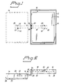
- FIG. 1 there is depicted a conference cabinet from the front according to a preferred embodiment of the invention.
- the conference cabinet consists of a board 10 having a wipeable writing surface made of, for example, whiteboard, and surrounded by a frame 12 of a certain thickness.
- the important thing about the frame 12 is that its thickness is selected so as for the writing surface 10, a board 14 with a flip-over pad and any other accessories such as writing materials, fastening magnets 16, a projection screen and the like to be included in the frame 12, if required, when the conference cabinet is not in use, i.e. is in its parking position.
- Fig. 1 there is also shown the board 14 which provides a support for a flip-over pad, where the flip-over pad is attached to the upper horizontal edge of the board 14 on the surface remote from the wipeable writing surface of the first board 10 (not shown).
- the support board 14 is shown in the retracted and extended position respectively, the latter position also being called working position and shown in broken line.
- To the right in Figure 1 the support board 14 is parked in the frame.12 and to the left it is extended beside it.
- the support board 14 is attached to the frame 12 by means of an armlike connection means 18 which at one end is attached to the support board 14 by a fastening element 20 and a hinge means 22, and at the other end is attached to the frame 12 by a second fastening element 24 and a second hinge means 26.
- the hinge means 22, 26 may be, for example, coupling bolts.
- the connection means 18, the first fastening element 20 and the first coupling bolt 22 are located between the two boards 10 and 14 and are therefore shown in broken line.
- a portion of the connection means 18, the entire first fastening element 20 and the first coupling bolt 22 are located behind the support board 14, and are therefore shown in broken line here too.
- a magnet 16 attached to the support board 14 which magnet in the parking position holds the support board 14 against the writing surface 10 and in the working position holds the support board 14 against the connection means 18.
- FIG 2 there is shown the movement of the support board 14 from the parking position to the working position.
- the connection means 18, which is L-shaped, is turned around a rotation axis 30 extending through the longitudinal axis of the second coupling bolt 26, and the support board 14 will turn around a rotation axis 32 extending through the longitudinal axis of the first coupling bolt 22, so that the support board 14 will assume the extended position.
- the support board 14 will then describe a semi-circular path shown in broken line in Figure 2.
- the front 33 of the support board 14 will be remote from the writing surface 10 the whole time.
- Figures 3 and 4 show the conference cabinet with the support board 14 in parking position and extended position, respectively.
- the cabinet is shown from the left and in Figure 4 from the the right.
- the two axes 30 and 32 around which the support board 14 and the connection means 18 are turned.
- the second axis 30 is vertical and the first axis 32 is inclined at an angle ⁇ relative to the vertical plane and the surface 10.
- the support board turns around the first tilted axis 32 so as to make in the entirely extended position a double angle 2 ⁇ relative to the axis 30.
- the support board 14 should always be turned fully (180°) around the first tilted axis 32 in order to achieve the correct angle 2 ⁇ relative to the axis 30 and in order for the lower edge of the support board 14 always to be horizontal.
- the turning of the connection means 18 around the second vertical axis may be varied.
- Figures 5 - 9 show the fastening elements 20 and 24 and the coupling bolts 22 and 26 of the device according to the invention.
- Figure 5 is a side view from the front of the second coupling bolt 26, the second fastening element 24, the connection means 18 and the first fastening element 20 in the parking position
- Figure 6 shows the same thing but in a side view from above showing the first coupling bolt 22 also.
- the fastening elements 20 and 24 have plane vertical portions 36 and 38 which are attached to the support board 14 and the frame 12 respectively and from each such portion 36, 38 two substantially triangular portions 40 and 42 provided with holes protrude perpendicularly and horizontally.
- connection means 18 may be inserted in the spaces defined by said portions.
- the ends of the connection means 18 are provided with holes too, such that a coupling bolt 22 or 26 may connect an end of the connection means 18 with a fastening element 20 or 24.
- an adjustment screw 34 there is shown an adjustment screw 34, the function of which will be explained below.
- the connection means 18 is arranged to turn around the coupling bolt 26 in the second fastening element 24, and the support board 14, which is attached with its rear side (not shown) against the plane vertical portion 36 of the first fastening element 20, is arranged to turn around the first axis 32 through the coupling bolt 22.
- Figure 7 shows the corresponding means from Figure 6 seen from above, for the support board 14 in the extended position.
- the first fastening element 20 is tilted, where the position of the first coupling bolt 22 at the underside of the fastening element 20 is shown in a broken circle. It is evident from the broken lines and from the fact that its plane vertical portion 36 is partly visible in this figure that the fastening element 20 is tilted.
- This figure shows the function of the adjustment screw 34. It sees to it that the connection means 18 and therefore the support board 14 are not extended more than required. The object of the same it to limit the turning angle of the connection means 18 such that the support board 14 may be oriented towards the centre of the room in which the conference cabinet is placed.
- Figure 8 is a side view of fastening elements 20 and 24 and coupling bolts 22 and 26 together with the connection means 18 seen from the right in Figure 1.
- the support board 14 here is inserted (not shown) and has its rear side attached to the plane vertical portion 36 of the first fastening element 20. Said portion 36 is parallel to the plane of the wipeable writing surface 10 (not shown).
- the coupling bolt 22 is tilted relative to the rotation axis 30 and relative to the plane vertical portion 36 of the first fastening element 20, and the rotation axis 32 extending through the longitudinal axis of the coupling bolt 22.
- the second fastening element 24 and the vertically oriented coupling bolt 26 are also shown.
- connection means 18 har partly angled end surfaces at the end attached to the first fastening element 20 with the tilted coupling bolt 22 and that the protruding triangular portions 42 of the first fastening element 20 are also partly angled, where the angled portions of the respective means have been angled such that said portions are perpendicular to the tilted rotation axis 32.
- Figure 9 shows the first fastening element 20 together with the tilted coupling bolt 22 and the connection means 18, for the extended position of the support board 14, relative to the second rotation axis 30, seen from the left in Figure 1.
- moving of the support board 14 into the extended position turns the connection means 18 around the rotation axis 30 and the first fastening element 20 (support board) around the tilted rotation axis 32 such that the rotation axis 32 has changed its inclination relative to the writing surface 10.
- a second writing surface such as a cabinet door covering the support board or two cabinet doors opening in opposite directions, one with a flip-over pad support which is tilted on opening and one with a writing board.
- the support board may also be hung from the opposite side of the document cabinet, i.e. be turned outwards to the right from the document cabinet instead of towards the left by altering the mounting of the tilted coupling bolt.
Landscapes
- Drawing Aids And Blackboards (AREA)
- Purses, Travelling Bags, Baskets, Or Suitcases (AREA)
Description
Claims (4)
- A conference cabinet comprising a first plane board (14) and a second plane board (10), the first plane board (14) in a first position being parallel to and at least partly covering the second plane board (10), the first plane board (14) in a second position being tiltable relative to the second plane board (10), and including a device for moving and tilting the first plane board (14), relative to the second plane board (10), characterized in that the device comprises a connection means (18) between the two boards, wherein one end of said connection means (18) is turnably attached to the first plane board (14) around a first axis (32) and the other end of said connection means (18) is turnably attached to or adjacent the second plane board (10) around a second axis (30), the first axis (32) being disposed, in use, vertically between the connection means (18) and the first plane board (14) and the second axis (30) being disposed, in use, vertically between the connection means (18) and the second plane board (10), and wherein the first axis (32) can be tilted at an angle (α) relative to the, in use, vertical plane of the second plane board (10).
- A conference cabinet according to claim 1, characterized in that the first axis (32) is provided through a hinge consisting of one end of the connection means (18) and a fastening element (20), which are interconnected by a hinge means (22) and the second axis (30) is provided through a hinge consisting of the other end of the connection means (18) and a second fastening element (24) which are interconnected by a second hinge means (26), the first axis (32) extending through the first hinge means (22) and the second axis (30) extending through the second hinge means (26).
- A conference cabinet according to claims 1 or 2, characterized in that the second board (10) is surrounded by the frame (12) and that the second fastening element (24) is fastened thereto.
- A conference cabinet according to any of the claims 1 - 3, characterized in that the second board (10) is provided with locking means (16), such as a magnet, and that the second surface (10) is arranged to detachably retain the first board (14) adjacent to itself in the first position and the connection means (18) is arranged to detachably retain the first board (14) adjacent to itself in the second position.
Applications Claiming Priority (3)
| Application Number | Priority Date | Filing Date | Title |
|---|---|---|---|
| SE9303878A SE501145C2 (en) | 1993-11-23 | 1993-11-23 | conference cabinet |
| SE9303878 | 1993-11-23 | ||
| PCT/SE1994/001107 WO1995014406A1 (en) | 1993-11-23 | 1994-11-21 | Conference cabinets |
Publications (2)
| Publication Number | Publication Date |
|---|---|
| EP0730419A1 EP0730419A1 (en) | 1996-09-11 |
| EP0730419B1 true EP0730419B1 (en) | 2001-04-04 |
Family
ID=20391853
Family Applications (1)
| Application Number | Title | Priority Date | Filing Date |
|---|---|---|---|
| EP95902368A Expired - Lifetime EP0730419B1 (en) | 1993-11-23 | 1994-11-21 | Conference cabinets |
Country Status (4)
| Country | Link |
|---|---|
| EP (1) | EP0730419B1 (en) |
| DE (1) | DE69427035T2 (en) |
| SE (1) | SE501145C2 (en) |
| WO (1) | WO1995014406A1 (en) |
Cited By (1)
| Publication number | Priority date | Publication date | Assignee | Title |
|---|---|---|---|---|
| US9718299B2 (en) | 2015-12-29 | 2017-08-01 | Clarus Glassboards, Llc | Flippable board method and system |
Family Cites Families (3)
| Publication number | Priority date | Publication date | Assignee | Title |
|---|---|---|---|---|
| US3659355A (en) * | 1970-11-02 | 1972-05-02 | Adelard L Aubin Jr | Wall mounted combination chalkboard, projector screen and information display apparatus |
| SE433292B (en) * | 1982-04-16 | 1984-05-21 | Johan Blomquist | Conference cabinet |
| DE9115475U1 (en) * | 1991-12-13 | 1992-04-02 | ProCent Patent- und Verwaltungs AG, Zürich | Interchangeable wall board system for visual communication |
-
1993
- 1993-11-23 SE SE9303878A patent/SE501145C2/en not_active IP Right Cessation
-
1994
- 1994-11-21 DE DE69427035T patent/DE69427035T2/en not_active Expired - Fee Related
- 1994-11-21 WO PCT/SE1994/001107 patent/WO1995014406A1/en not_active Ceased
- 1994-11-21 EP EP95902368A patent/EP0730419B1/en not_active Expired - Lifetime
Cited By (1)
| Publication number | Priority date | Publication date | Assignee | Title |
|---|---|---|---|---|
| US9718299B2 (en) | 2015-12-29 | 2017-08-01 | Clarus Glassboards, Llc | Flippable board method and system |
Also Published As
| Publication number | Publication date |
|---|---|
| SE9303878L (en) | 1994-11-28 |
| SE501145C2 (en) | 1994-11-28 |
| DE69427035T2 (en) | 2001-11-29 |
| EP0730419A1 (en) | 1996-09-11 |
| WO1995014406A1 (en) | 1995-06-01 |
| SE9303878D0 (en) | 1993-11-23 |
| DE69427035D1 (en) | 2001-05-10 |
Similar Documents
| Publication | Publication Date | Title |
|---|---|---|
| US4681381A (en) | Removable drawer slide and interlock with drawer | |
| US20050035253A1 (en) | Projector mount | |
| CN100497877C (en) | Device for forming a movable wall structure | |
| US20140158024A1 (en) | Table with privacy screen | |
| CA2040171A1 (en) | Support structure for television monitor | |
| DE102004009183A1 (en) | Display frame for a flat panel display device | |
| US5016390A (en) | Shutter assembly | |
| EP0730419B1 (en) | Conference cabinets | |
| US3323163A (en) | Hinge structure for flush overlay doors | |
| US6040979A (en) | Computer having module bay with variable insertion opening size | |
| US6304377B1 (en) | Wall and/or projection board | |
| US5749125A (en) | Hinge bracket for a cabinet door | |
| DE19818269A1 (en) | Diagonal insertion system | |
| JP7770961B2 (en) | Partitions and partition connectors | |
| US4139116A (en) | Cabinet with two or more drawers | |
| JPH06269321A (en) | Desk | |
| JPH03183883A (en) | Hinge device | |
| JP2518612Y2 (en) | Pivot hinge seat | |
| KR102845604B1 (en) | Top opening board having dislplasy device installed inside | |
| KR200437081Y1 (en) | Desk and photo frame | |
| JPH0994125A (en) | Support device for fall prevention tool, fall prevention device, and shelf | |
| JP3186782B2 (en) | Door opening and closing device | |
| JP2743244B2 (en) | Rotating window | |
| EP1057427A1 (en) | Cabinet | |
| JPH04368588A (en) | partition panel |
Legal Events
| Date | Code | Title | Description |
|---|---|---|---|
| PUAI | Public reference made under article 153(3) epc to a published international application that has entered the european phase |
Free format text: ORIGINAL CODE: 0009012 |
|
| 17P | Request for examination filed |
Effective date: 19960624 |
|
| AK | Designated contracting states |
Kind code of ref document: A1 Designated state(s): DE FR GB |
|
| 17Q | First examination report despatched |
Effective date: 19970521 |
|
| GRAG | Despatch of communication of intention to grant |
Free format text: ORIGINAL CODE: EPIDOS AGRA |
|
| GRAG | Despatch of communication of intention to grant |
Free format text: ORIGINAL CODE: EPIDOS AGRA |
|
| GRAH | Despatch of communication of intention to grant a patent |
Free format text: ORIGINAL CODE: EPIDOS IGRA |
|
| GRAH | Despatch of communication of intention to grant a patent |
Free format text: ORIGINAL CODE: EPIDOS IGRA |
|
| GRAA | (expected) grant |
Free format text: ORIGINAL CODE: 0009210 |
|
| AK | Designated contracting states |
Kind code of ref document: B1 Designated state(s): DE FR GB |
|
| PG25 | Lapsed in a contracting state [announced via postgrant information from national office to epo] |
Ref country code: FR Free format text: LAPSE BECAUSE OF FAILURE TO SUBMIT A TRANSLATION OF THE DESCRIPTION OR TO PAY THE FEE WITHIN THE PRESCRIBED TIME-LIMIT Effective date: 20010404 |
|
| REF | Corresponds to: |
Ref document number: 69427035 Country of ref document: DE Date of ref document: 20010510 |
|
| EN | Fr: translation not filed | ||
| REG | Reference to a national code |
Ref country code: GB Ref legal event code: IF02 |
|
| PLBE | No opposition filed within time limit |
Free format text: ORIGINAL CODE: 0009261 |
|
| STAA | Information on the status of an ep patent application or granted ep patent |
Free format text: STATUS: NO OPPOSITION FILED WITHIN TIME LIMIT |
|
| 26N | No opposition filed | ||
| PGFP | Annual fee paid to national office [announced via postgrant information from national office to epo] |
Ref country code: GB Payment date: 20041103 Year of fee payment: 11 |
|
| PGFP | Annual fee paid to national office [announced via postgrant information from national office to epo] |
Ref country code: DE Payment date: 20041125 Year of fee payment: 11 |
|
| PG25 | Lapsed in a contracting state [announced via postgrant information from national office to epo] |
Ref country code: GB Free format text: LAPSE BECAUSE OF NON-PAYMENT OF DUE FEES Effective date: 20051121 |
|
| PG25 | Lapsed in a contracting state [announced via postgrant information from national office to epo] |
Ref country code: DE Free format text: LAPSE BECAUSE OF NON-PAYMENT OF DUE FEES Effective date: 20060601 |
|
| GBPC | Gb: european patent ceased through non-payment of renewal fee |
Effective date: 20051121 |