EP0729663B1 - Open stator axial flux electric motor - Google Patents
Open stator axial flux electric motor Download PDFInfo
- Publication number
- EP0729663B1 EP0729663B1 EP95931087A EP95931087A EP0729663B1 EP 0729663 B1 EP0729663 B1 EP 0729663B1 EP 95931087 A EP95931087 A EP 95931087A EP 95931087 A EP95931087 A EP 95931087A EP 0729663 B1 EP0729663 B1 EP 0729663B1
- Authority
- EP
- European Patent Office
- Prior art keywords
- axial flux
- stator
- motor
- poles
- open
- Prior art date
- Legal status (The legal status is an assumption and is not a legal conclusion. Google has not performed a legal analysis and makes no representation as to the accuracy of the status listed.)
- Expired - Lifetime
Links
- 230000004907 flux Effects 0.000 title claims abstract description 30
- 238000004804 winding Methods 0.000 claims abstract description 35
- 239000000463 material Substances 0.000 claims abstract description 13
- 239000004020 conductor Substances 0.000 claims abstract description 5
- RYGMFSIKBFXOCR-UHFFFAOYSA-N Copper Chemical compound [Cu] RYGMFSIKBFXOCR-UHFFFAOYSA-N 0.000 claims description 6
- 229910052802 copper Inorganic materials 0.000 claims description 6
- 239000010949 copper Substances 0.000 claims description 6
- 229910000963 austenitic stainless steel Inorganic materials 0.000 claims description 4
- 230000010349 pulsation Effects 0.000 claims description 3
- 229910000976 Electrical steel Inorganic materials 0.000 claims description 2
- 230000006698 induction Effects 0.000 abstract description 2
- 238000010276 construction Methods 0.000 description 6
- 230000005291 magnetic effect Effects 0.000 description 5
- XEEYBQQBJWHFJM-UHFFFAOYSA-N Iron Chemical compound [Fe] XEEYBQQBJWHFJM-UHFFFAOYSA-N 0.000 description 4
- 238000003475 lamination Methods 0.000 description 4
- 241000555745 Sciuridae Species 0.000 description 3
- 238000005461 lubrication Methods 0.000 description 3
- 229910001208 Crucible steel Inorganic materials 0.000 description 2
- 238000010586 diagram Methods 0.000 description 2
- 239000003302 ferromagnetic material Substances 0.000 description 2
- 229910052742 iron Inorganic materials 0.000 description 2
- 238000003466 welding Methods 0.000 description 2
- 235000011464 Pachycereus pringlei Nutrition 0.000 description 1
- 240000006939 Pachycereus weberi Species 0.000 description 1
- 235000011466 Pachycereus weberi Nutrition 0.000 description 1
- 239000004411 aluminium Substances 0.000 description 1
- 229910052782 aluminium Inorganic materials 0.000 description 1
- XAGFODPZIPBFFR-UHFFFAOYSA-N aluminium Chemical compound [Al] XAGFODPZIPBFFR-UHFFFAOYSA-N 0.000 description 1
- 230000003466 anti-cipated effect Effects 0.000 description 1
- RYGMFSIKBFXOCR-AKLPVKDBSA-N copper-67 Chemical compound [67Cu] RYGMFSIKBFXOCR-AKLPVKDBSA-N 0.000 description 1
- RYGMFSIKBFXOCR-RNFDNDRNSA-N copper-68 Chemical compound [68Cu] RYGMFSIKBFXOCR-RNFDNDRNSA-N 0.000 description 1
- 230000000694 effects Effects 0.000 description 1
- 238000010438 heat treatment Methods 0.000 description 1
- 239000011810 insulating material Substances 0.000 description 1
- 239000000314 lubricant Substances 0.000 description 1
- 238000003754 machining Methods 0.000 description 1
- 238000012423 maintenance Methods 0.000 description 1
- 229910052751 metal Inorganic materials 0.000 description 1
- 239000002184 metal Substances 0.000 description 1
- 150000002739 metals Chemical class 0.000 description 1
- 229910000679 solder Inorganic materials 0.000 description 1
Images


Classifications
-
- H—ELECTRICITY
- H02—GENERATION; CONVERSION OR DISTRIBUTION OF ELECTRIC POWER
- H02K—DYNAMO-ELECTRIC MACHINES
- H02K1/00—Details of the magnetic circuit
- H02K1/06—Details of the magnetic circuit characterised by the shape, form or construction
- H02K1/12—Stationary parts of the magnetic circuit
- H02K1/18—Means for mounting or fastening magnetic stationary parts on to, or to, the stator structures
- H02K1/182—Means for mounting or fastening magnetic stationary parts on to, or to, the stator structures to stators axially facing the rotor, i.e. with axial or conical air gap
-
- H—ELECTRICITY
- H02—GENERATION; CONVERSION OR DISTRIBUTION OF ELECTRIC POWER
- H02K—DYNAMO-ELECTRIC MACHINES
- H02K1/00—Details of the magnetic circuit
- H02K1/06—Details of the magnetic circuit characterised by the shape, form or construction
- H02K1/12—Stationary parts of the magnetic circuit
-
- H—ELECTRICITY
- H02—GENERATION; CONVERSION OR DISTRIBUTION OF ELECTRIC POWER
- H02K—DYNAMO-ELECTRIC MACHINES
- H02K17/00—Asynchronous induction motors; Asynchronous induction generators
- H02K17/02—Asynchronous induction motors
- H02K17/12—Asynchronous induction motors for multi-phase current
-
- H—ELECTRICITY
- H02—GENERATION; CONVERSION OR DISTRIBUTION OF ELECTRIC POWER
- H02K—DYNAMO-ELECTRIC MACHINES
- H02K17/00—Asynchronous induction motors; Asynchronous induction generators
- H02K17/02—Asynchronous induction motors
- H02K17/16—Asynchronous induction motors having rotors with internally short-circuited windings, e.g. cage rotors
- H02K17/165—Asynchronous induction motors having rotors with internally short-circuited windings, e.g. cage rotors characterised by the squirrel-cage or other short-circuited windings
-
- H—ELECTRICITY
- H02—GENERATION; CONVERSION OR DISTRIBUTION OF ELECTRIC POWER
- H02K—DYNAMO-ELECTRIC MACHINES
- H02K17/00—Asynchronous induction motors; Asynchronous induction generators
- H02K17/02—Asynchronous induction motors
- H02K17/16—Asynchronous induction motors having rotors with internally short-circuited windings, e.g. cage rotors
- H02K17/20—Asynchronous induction motors having rotors with internally short-circuited windings, e.g. cage rotors having deep-bar rotors
-
- H—ELECTRICITY
- H02—GENERATION; CONVERSION OR DISTRIBUTION OF ELECTRIC POWER
- H02K—DYNAMO-ELECTRIC MACHINES
- H02K3/00—Details of windings
- H02K3/04—Windings characterised by the conductor shape, form or construction, e.g. with bar conductors
- H02K3/28—Layout of windings or of connections between windings
-
- H—ELECTRICITY
- H02—GENERATION; CONVERSION OR DISTRIBUTION OF ELECTRIC POWER
- H02K—DYNAMO-ELECTRIC MACHINES
- H02K2201/00—Specific aspects not provided for in the other groups of this subclass relating to the magnetic circuits
- H02K2201/06—Magnetic cores, or permanent magnets characterised by their skew
Definitions
- THIS INVENTION relates to an electric machine.
- the invention concerns an open stator axial flux electric (OSAF) motor.
- OSAF open stator axial flux electric
- the invention will be described by way of example with reference to a preferred application or use of the motor.
- This preferred use or application employs the motor of the invention as a traction motor for driving a railway bogie. It should be appreciated that this is by way of example only and tha the motor of the invention may be employed in other applications and for other purposes.
- Traction motors for rail bogies in recent times typically are three phase asynchronous motors powered by an inverter controlled bridge providing a three phase AC voltage of about 750 to 2000 VAC depending upon the particular traction system used.
- Such traction motors have a stator and a rotor with the rotor operating at relatively high speeds.
- Electronic converters/inverters e.g. pulse width modulation
- the motor is typically of a squirrel cage design.
- the high speed range is necessary to take advantage of the high torque characteristic at high rotational speed of conventional three phase machines.
- High motor speed over 4000 rpm and up to 6500 rpm requires special bearing design and lubrication attentic for heavy engineering, marine and traction applications. Difficulties arise with low starting speed, lubricant film levels and over-lubrication and heating at the high speed. Shorter bearing life and shorter maintenance periods for bearing lubrication are a reality.
- High motor speed requires expensive drive train and gear box design. It is time consuming and expensive to change an element of a drive system e.g. wheel or motor in a rail traction system.
- Traction motor construction is such that there is no stator case or housing and the stator laminations form the body of the motor. A catastrophic rotor failure or a stator winding failure may require complete replacement of the motor.
- an open stator axial flux electric motor including:
- the shaft which forms part of the rotor is preferably made from a non-magnetically permeable material. In this way the flux leakage paths from one of the rotor discs to the other of the rotor discs are minimised and the magnetic paths are contained within the discs and the stator poles. Fringing and losses may be reduced by such a choice of shaft material.
- the shaft is made from an austenitic stainless steel although other non-magnetically permeable materials may also be used e.g. the relative permittivity of about 1.03 for austenitic stainless steel is particularly preferred.
- the rotor discs may have an inner electrically conductive layer or have an inner face capable of providing conductive paths to form rotor windings.
- a particular preferred conductive layer may be provided by forming each disc of magnetically permeable material faced with a sheet of copper on an inner face thereof.
- the discs may be made of cast steel and the copper layer may be of a thickness of between 1 to 6 mm although other suitable thicknesses are not excluded.
- the copper layer may be secured in place in any suitable fashion such as for example by silver solder or T.I.G. welding, or in fact the layer itself may be manufactured by using continuous T.I.G. welding in a spiral and then machining the weld to provide a flat surface.
- the conductive layer mentioned above is referred to as being copper, other electrically conductive metals such as aluminium may also be used.
- the inner face of the discs may be provided by a radially inner and a radially outer conductive shorting rings of electrically conductive material provided on the inner face of the rotor discs with substantially radially extending electrically conductive bars extending between the shorting rings.
- a configuration may be thought of as being analogous in function and purpose to a squirrel cage rotor construction employed in a typical squirrel cage induction machine.
- the radially extending bars may either extend exactly radially of the discs or may be skewed to that radial direction to reduce torque pulsation in use.
- the open stator has poles provided by pole pieces either having distributed windings or salient pole windings.
- the motor of the invention may have three pole phase groups as a minimum although a greater number is preferred. The number of pole phase groups employed may either be even or uneven.
- the term "open stator” denotes the fact that there are no poles in a sector of the circular path about which the poles are located. This fact together with the provision of a slot in each of the supports for the poles enables the rotor shaft to be received and located within the slots provided in the supports and within the open sector during operation of the motor. Likewise, the rotor is readily separable from the stator and can readily be removed from the stator if required.
- pole phase groups Preferably there are more than three pole phase groups.
- a six pole motor is preferred although a seven pole motor is particularly preferred.
- Each individual coil pole of a phase group includes a pole piece of magnetically permeable material. It is preferred that the pole pieces be substantially wedge shaped and made of a plurality of pieces laminated to each other. However laminated rectangular pole pieces may be used for complex distributed windings. By having the poles made of laminations eddy current losses may be reduced.
- the poles are preferably made of laminated silicon steel pieces or wedges.
- the windings may either be distributed windings or salient pole windings with any unexcited poles being located adjacent the open ends of the stator. It is preferred that the number of windings be present in multiples of three. For example the number of windings may comprise a six pole stator with four phase groups, a seven pole stator with five phase groups or any other suitable configuration. It is particularly preferred that an odd number of poles be employed and that the pole pieces adjacent the open sector be unexcited.
- the pole pieces are preferably longer than the coils are high. This enables the pole pieces to be more easily secured to the supports.
- One way of securing the pole pieces to the supports is to provide the supports with wedge shaped apertures into which ends of the pole pieces may project and the pole pieces may be clamped between the two supports.
- Figure 1 shows a preferred construction of a wedge shaped pole piece 10.
- the pole piece is comprised of laminations 11 to 18 and as a compromise, these laminations are plate like in configuration to provide an approximation to a wedge shape.
- Figure 2 shows the pole piece 10 with a salient pole winding 19 extending around it.
- the pole piece 10 extends a short distance beyond opposed ends of the winding 19 for reasons explained below.
- Figure 3 shows the manner in which a plurality of pole pieces 20 to 36 are arranged around a circular path with an open sector 37 to provide a seven pole motor having five active coil phase groups.
- Pole pieces 20 and 36 adjacent the open sector 37 are unexcited and salient pole windings 38 to 52 are associated with pole pieces 21 to 35 respectively.
- the number of salient wound coils are a multiple of three.
- the salient pole windings employ a three phase driving current to develop a rotating magnetic field.
- the coil phase groups adjacent the opening in the stator are of the same polarity and this reduces the open end flux path loss.
- a non-excited laminated pole piece is used adjacent either side of the opening in the stator. This converts the flux into a useful path through the rotor discs.
- the rotor shaft should be made of a non-ferromagnetic material such as an austenitic stainless steel with a relative permittivity of about 1.03.
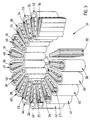
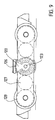
- Figure 4 shows the pole pieces 20 to 36 mounted to opposed stator supports 60, 61.
- Each support 60, 61 has apertures into which the pole pieces project.
- the supports are clamped together against the salient pole windings.
- the supports are made of insulating material and are each provided with a slot 62, 63 at a location next to the opening between the non-excited pole pieces 20, 36.
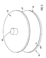
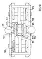
- Figure 5 shows a perspective view of a rotor 64.
- the rotor has two rotor discs 65, 66 made magnetically permeable cast steel.
- Each disc has an inner surface faced with a circular sheet of copper 67, 68 and a shaft 69 extending through and beyond the outer faces of the discs.
- the stator shown in Figure 4 is received between the discs with the shaft 69 extending through the slots 62, 63.
- the rotor 70 in Figure 6 has a shaft 71 and two spaced rotor discs 72, 73.
- the discs are provided with rotor windings consisting of an inner and an outer shorting rings 74, 75.
- Conductive bars 76 extend between the rings 74, 75. Although the bars 76 may extend radially of the discs, in this embodiment the bars are skewed as shown to reduce torque pulsations in use.
- the bars and rings may be embedded into the discs and need not necessarily be visible when the rotor is configured in this way.
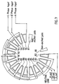
- FIG. 7 shows one way in which the stator of the invention may be wound.
- the stator has two non excited poles 80, 81.
- the remaining poles 82 to 96 are excited with respective ones of the phase currents A, B or C in the manner illustrated.
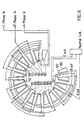
- FIG 8 shows one way in which the stator of the invention may be wound.
- the stator has two non excited poles 100, 101.
- the remaining poles 102 to 116 are excited with distributed windings supplied with current from phases A, B and C.
- Figures 9 and 10 are useful in understanding how the motor of the invention is employed in a railway bogie.
- Figure 9 is a side elevational view of a bogie which has the motor 120 mounted between two transversely spaced bogie frame members, the motor is shown in dark outline to indicate its position relative to the bogie. Normally the motor would be obscured from view by one of the transverse frame members.
- the motor 120 is positioned such that the slots in the stator and the gap between the poles near the slots is uppermost.
- the motor 120 is supported and mounted to the bogie by a support frame 121 and support beams 122.
- Part of the frame 121 has been removed for the sake of clarity. That part normally extends above the motor and has a keeper secured to a portion of the stator adjacent the slots in the stator.
- the rotor shaft 123 and the rotor discs are clearly visible in Figure 10. Opposite ends of the shaft 123 are supported in bearings 124. Gearboxes 125 are secured to opposite sides of the bogie and consist of a primary drive gear 126 on the rotor shaft, an intermediate drive gear 127 supported by the gearbox and a final gear/cardon quill shaft 128.
- stator is supported from below and the lateral support beams 122 and the support frame and keeper 129 are disconnected from the stator.
- the stator may then be lowered and removed.
- the rotor remains in position relative to the bogie and need not be disconnected from the gearbox or bearings.
- stator is able to remain securely coupled to the bogie and does not need to be disturbed.
- the diameter of the rotor discs is preferably chosen to be greater than the diameter about which the poles on the stator are located. In this way the discs extend past the stator pole radius. This allows the induced loop currents of the rotor to return outside the main stator magnetic flux. Therefore with such a configuration there is a reduction in the development of counter motive forces between the rotor and the stator.
- the OSAF motor is of a relatively simple construction.
- the rotor and stator can be changed and handled separately in its example application with a railway bogie. If stator failure occurs, the rotor and associated drive gear train do not need to be disturbed during stator change-over or stator individual coil replacements.
- a motor constructed in accordance with the present invention has a lower running speed than a design having more poles for a similar volume.
- the motor has a field rotation (rpm) of 2 x supply frequency x 60 N where
- the torque developed by the motor of the invention is developed at a larger force radius to compensate for lower operating speeds.
- the lower operating speeds place less constraints on the bearings and drive gear train and this allows for a simpler design for the bearings and gear train. Since there is no need for stationary back iron in the stator it is almost impossible to have a phase to earth failure and because less material is employed in the construction of the motor a weight saving is possible. For a salient pole stator winding design (as opposed to a distributing winding design) it is almost impossible to have phase to phase failures because each phase is physically separated.
- the stator of the motor according to the invention requires no stationary back iron and this reduces losses.
Abstract
Description
- THIS INVENTION relates to an electric machine. In particular, the invention concerns an open stator axial flux electric (OSAF) motor.
- The invention will be described by way of example with reference to a preferred application or use of the motor. This preferred use or application employs the motor of the invention as a traction motor for driving a railway bogie. It should be appreciated that this is by way of example only and tha the motor of the invention may be employed in other applications and for other purposes.
- Traction motors for rail bogies in recent times typically are three phase asynchronous motors powered by an inverter controlled bridge providing a three phase AC voltage of about 750 to 2000 VAC depending upon the particular traction system used.
- Such traction motors have a stator and a rotor with the rotor operating at relatively high speeds.
- Electronic converters/inverters (e.g. pulse width modulation) are used to develop the variable frequency traction drive three phase supply to power and control the motor. The motor is typically of a squirrel cage design. The high speed range is necessary to take advantage of the high torque characteristic at high rotational speed of conventional three phase machines.
- High motor speed over 4000 rpm and up to 6500 rpm requires special bearing design and lubrication attentic for heavy engineering, marine and traction applications. Difficulties arise with low starting speed, lubricant film levels and over-lubrication and heating at the high speed. Shorter bearing life and shorter maintenance periods for bearing lubrication are a reality.
- High motor speed requires expensive drive train and gear box design. It is time consuming and expensive to change an element of a drive system e.g. wheel or motor in a rail traction system.
- Traction motor construction is such that there is no stator case or housing and the stator laminations form the body of the motor. A catastrophic rotor failure or a stator winding failure may require complete replacement of the motor.
- It is an object of the invention to provide an improved electric motor for use as a drive system, e.g. a traction motor for railway bogies.
- According to one aspect the invention provides an open stator axial flux electric motor including:
- an open stator including two spaced insulating supports with a slot extending from a periphery of each of the supports to an inner location thereof, a plurality of poles with pole pieces extending between the supports and secured thereto, the pole pieces being made of magnetically permeable material and arranged along a circular path around the supports, the stator having either distributed windings or salient phase pole windings associated with at least some of the pole pieces with an opening between adjacent pole pieces in the region of the slots in the supports;
- a rotor having a shaft locatable in and extending through the slots and extending at right angles to the supports, two spaced rotor discs on the shaft with a respective said disc located on the shaft and either side of the stator, each disc being constructed of magnetically permeable material and having either an inner face of electrically conductive material or an inner face with conductive paths providing rotor windings, the shaft being supported for rotation relative to the rotor.
-
- The shaft which forms part of the rotor is preferably made from a non-magnetically permeable material. In this way the flux leakage paths from one of the rotor discs to the other of the rotor discs are minimised and the magnetic paths are contained within the discs and the stator poles. Fringing and losses may be reduced by such a choice of shaft material. In one embodiment the shaft is made from an austenitic stainless steel although other non-magnetically permeable materials may also be used e.g. the relative permittivity of about 1.03 for austenitic stainless steel is particularly preferred.
- As mentioned, the rotor discs may have an inner electrically conductive layer or have an inner face capable of providing conductive paths to form rotor windings. A particular preferred conductive layer may be provided by forming each disc of magnetically permeable material faced with a sheet of copper on an inner face thereof. The discs may be made of cast steel and the copper layer may be of a thickness of between 1 to 6 mm although other suitable thicknesses are not excluded. The copper layer may be secured in place in any suitable fashion such as for example by silver solder or T.I.G. welding, or in fact the layer itself may be manufactured by using continuous T.I.G. welding in a spiral and then machining the weld to provide a flat surface.
- Although the conductive layer mentioned above is referred to as being copper, other electrically conductive metals such as aluminium may also be used.
- As an alternative to providing a layer of electrically conductive material on the inner face of the rotor discs to form the rotor windings, the following configurations may be adopted. The inner face of the discs may be provided by a radially inner and a radially outer conductive shorting rings of electrically conductive material provided on the inner face of the rotor discs with substantially radially extending electrically conductive bars extending between the shorting rings. Such a configuration may be thought of as being analogous in function and purpose to a squirrel cage rotor construction employed in a typical squirrel cage induction machine. If desired, the radially extending bars may either extend exactly radially of the discs or may be skewed to that radial direction to reduce torque pulsation in use.
- The open stator, as mentioned, has poles provided by pole pieces either having distributed windings or salient pole windings. The motor of the invention may have three pole phase groups as a minimum although a greater number is preferred. The number of pole phase groups employed may either be even or uneven. The term "open stator" denotes the fact that there are no poles in a sector of the circular path about which the poles are located. This fact together with the provision of a slot in each of the supports for the poles enables the rotor shaft to be received and located within the slots provided in the supports and within the open sector during operation of the motor. Likewise, the rotor is readily separable from the stator and can readily be removed from the stator if required.
- Preferably there are more than three pole phase groups. In one embodiment a six pole motor is preferred although a seven pole motor is particularly preferred.
- Each individual coil pole of a phase group includes a pole piece of magnetically permeable material. It is preferred that the pole pieces be substantially wedge shaped and made of a plurality of pieces laminated to each other. However laminated rectangular pole pieces may be used for complex distributed windings. By having the poles made of laminations eddy current losses may be reduced. The poles are preferably made of laminated silicon steel pieces or wedges.
- It is not necessary that all poles be excited. Thus, the poles immediately adjacent the vacant sector need not be excited. As mentioned, the windings may either be distributed windings or salient pole windings with any unexcited poles being located adjacent the open ends of the stator. It is preferred that the number of windings be present in multiples of three. For example the number of windings may comprise a six pole stator with four phase groups, a seven pole stator with five phase groups or any other suitable configuration. It is particularly preferred that an odd number of poles be employed and that the pole pieces adjacent the open sector be unexcited.
- The pole pieces are preferably longer than the coils are high. This enables the pole pieces to be more easily secured to the supports. One way of securing the pole pieces to the supports is to provide the supports with wedge shaped apertures into which ends of the pole pieces may project and the pole pieces may be clamped between the two supports.
- Preferred embodiments of the invention will now be described with reference to the drawings in which:
- Figure 1 is a perspective view of a pole piece according to an embodiment of the invention;
- Figure 2 is a perspective view of the pole piece of Figure 1 with a salient pole winding;
- Figure 3 is a perspective view of a plurality of pole pieces showing the configuration adopted for an open stator axial flux motor having seven pole groups of three phases (five active poles);
- Figure 4 is a perspective view of the pole pieces of Figure 3 secured to supports;
- Figure 5 is a perspective view of a rotor according to a preferred embodiment of the invention;
- Figure 6 is a perspective view of a rotor according to another embodiment of the invention;
- Figure 7 is a winding diagram for a salient pole OSAF motor according to an embodiment of the invention;
- Figure 8 is a winding diagram for a distributed pole OSAF motor according to an embodiment of the invention;
- Figure 9 is an elevational view of a railway bogie incorporating a motor according to an embodiment of the invention; and
- Figure 10 is a plan view of the bogie shown in Figure 9.
-
- Figure 1 shows a preferred construction of a wedge shaped
pole piece 10. The pole piece is comprised of laminations 11 to 18 and as a compromise, these laminations are plate like in configuration to provide an approximation to a wedge shape. - Figure 2 shows the
pole piece 10 with a salient pole winding 19 extending around it. Thepole piece 10 extends a short distance beyond opposed ends of the winding 19 for reasons explained below. - Figure 3 shows the manner in which a plurality of
pole pieces 20 to 36 are arranged around a circular path with anopen sector 37 to provide a seven pole motor having five active coil phase groups.Pole pieces open sector 37 are unexcited andsalient pole windings 38 to 52 are associated withpole pieces 21 to 35 respectively. Thus, the number of salient wound coils are a multiple of three. The salient pole windings employ a three phase driving current to develop a rotating magnetic field. - A study conducted of anticipated magnetic main (useful) and leakage flux paths for a six pole OSAF motor (i.e. four active coil phase groups) and a seven pole OSAF motor (i.e. five active coil phase groups) has been carried out to determine whether an odd or even number of phase coil should be used and to establish the losses due to the open stator configuration. This study revealed that, as expected, leakage flux path losses were high in the open ends as the phase coil polarity was opposite on each of the open stator ends in a six pole OSAF motor. Similarly losses occurred due to the magnetic bridge formed by the rotor shaft if made of ferromagnetic material. Normal fringing losses occur on the outer disc edges and between the phase coils.
- By employing an odd number of poles for the open stator the coil phase groups adjacent the opening in the stator are of the same polarity and this reduces the open end flux path loss. To convert the leakage around the end coil a non-excited laminated pole piece is used adjacent either side of the opening in the stator. This converts the flux into a useful path through the rotor discs. To further reduce losses, as previously mentioned, the rotor shaft should be made of a non-ferromagnetic material such as an austenitic stainless steel with a relative permittivity of about 1.03.
- Figure 4 shows the
pole pieces 20 to 36 mounted to opposed stator supports 60, 61. Eachsupport slot non-excited pole pieces - Figure 5 shows a perspective view of a
rotor 64. The rotor has tworotor discs 65, 66 made magnetically permeable cast steel. Each disc has an inner surface faced with a circular sheet ofcopper 67, 68 and ashaft 69 extending through and beyond the outer faces of the discs. In use, the stator shown in Figure 4 is received between the discs with theshaft 69 extending through theslots - The
rotor 70 in Figure 6 has ashaft 71 and two spacedrotor discs discs Conductive bars 76 extend between therings bars 76 may extend radially of the discs, in this embodiment the bars are skewed as shown to reduce torque pulsations in use. The bars and rings may be embedded into the discs and need not necessarily be visible when the rotor is configured in this way. - Figure 7 shows one way in which the stator of the invention may be wound. In this figure, the stator has two non
excited poles 80, 81. The remaining poles 82 to 96 are excited with respective ones of the phase currents A, B or C in the manner illustrated. - Figure 8 shows one way in which the stator of the invention may be wound. In this figure, the stator has two non
excited poles poles 102 to 116 are excited with distributed windings supplied with current from phases A, B and C. - Figures 9 and 10 are useful in understanding how the motor of the invention is employed in a railway bogie. Although Figure 9 is a side elevational view of a bogie which has the
motor 120 mounted between two transversely spaced bogie frame members, the motor is shown in dark outline to indicate its position relative to the bogie. Normally the motor would be obscured from view by one of the transverse frame members. - The
motor 120 is positioned such that the slots in the stator and the gap between the poles near the slots is uppermost. Themotor 120 is supported and mounted to the bogie by asupport frame 121 and support beams 122. Part of theframe 121 has been removed for the sake of clarity. That part normally extends above the motor and has a keeper secured to a portion of the stator adjacent the slots in the stator. - The
rotor shaft 123 and the rotor discs are clearly visible in Figure 10. Opposite ends of theshaft 123 are supported inbearings 124.Gearboxes 125 are secured to opposite sides of the bogie and consist of aprimary drive gear 126 on the rotor shaft, anintermediate drive gear 127 supported by the gearbox and a final gear/cardon quill shaft 128. - If it proves necessary to remove the stator from the bogie the following steps are necessary. The stator is supported from below and the lateral support beams 122 and the support frame and keeper 129 are disconnected from the stator. The stator may then be lowered and removed. The rotor remains in position relative to the bogie and need not be disconnected from the gearbox or bearings.
- If it proves necessary to remove the rotor then the rotor needs to be decoupled from the bearings and gearbox and separated from the bogie. The stator is able to remain securely coupled to the bogie and does not need to be disturbed.
- The diameter of the rotor discs is preferably chosen to be greater than the diameter about which the poles on the stator are located. In this way the discs extend past the stator pole radius. This allows the induced loop currents of the rotor to return outside the main stator magnetic flux. Therefore with such a configuration there is a reduction in the development of counter motive forces between the rotor and the stator.
- A similar effect is also possible where, rather than the discs having conductive faces, they are provided with conductive shorting rings and conductive bars extending between the rings. With such a construction the rings should be outside the radius of the poles.
- The OSAF motor is of a relatively simple construction. The rotor and stator can be changed and handled separately in its example application with a railway bogie. If stator failure occurs, the rotor and associated drive gear train do not need to be disturbed during stator change-over or stator individual coil replacements. A motor constructed in accordance with the present invention has a lower running speed than a design having more poles for a similar volume. The motor has a field rotation (rpm) of
- N =
- number of stator three phase coil/pole groups in an imaginary full stator annulus (i.e. as if the motor were a full axial flux stator.
- The torque developed by the motor of the invention is developed at a larger force radius to compensate for lower operating speeds. The lower operating speeds place less constraints on the bearings and drive gear train and this allows for a simpler design for the bearings and gear train. Since there is no need for stationary back iron in the stator it is almost impossible to have a phase to earth failure and because less material is employed in the construction of the motor a weight saving is possible. For a salient pole stator winding design (as opposed to a distributing winding design) it is almost impossible to have phase to phase failures because each phase is physically separated.
- The stator of the motor according to the invention requires no stationary back iron and this reduces losses.
Claims (18)
- An open stator axial flux electric motor including:an open stator including two spaced insulating supports (60, 61) with a slot (62, 63) extending from a periphery of each of the supports (60, 61) to an inner location thereof, a plurality of poles with pole pieces (20-36) extending between the supports and secured thereto, the pole pieces (20-36) being made of magnetically permeable material and arranged along a circular path around the supports (60, 61), the stator having either distributed windings or salient phase pole windings (38-52) associated with at least some of the pole pieces (20-36) with an opening (37) between adjacent pole pieces in the region of the slots (62, 63) in the supports;a rotor (64, 70) having a shaft (69, 71) locatable in and extending through the slots (62, 63) and extending at right angles to the supports (60, 61), two spaced rotor discs (65, 66, 72, 73) on the shaft (69, 71) with a respective said disc located on the shaft and either side of the stator, each disc being constructed of magnetically permeable material and having either an inner face of electrically conductive material (67, 68), or an inner face with conductive paths providing rotor windings (74, 75), the shaft being supported for rotation relative to the stator.
- The open stator axial flux electric motor of Claim 1 wherein the rotor (64, 70) is made from a non-magnetically permeable material.
- The open stator axial flux electric motor of Claim 2 wherein the shaft (69, 71) is made from austenitic stainless steel.
- The open stator axial flux electric motor of Claim 1 wherein an inner face (67, 68) of each of the discs (65, 66) has a layer of copper secured to it.
- The open stator axial flux electric motor of Claim 4 wherein the layer of copper is between 1 to 6 mm thick.
- The open stator axial flux electric motor of Claim 1 wherein the conductive paths are provided by a radially inner and a radially outer conductive shorting rings (74, 75) with substantially radially extending conductive bars (76) extending between the shorting rings.
- The open stator axial flux electric motor of Claim 6 wherein the radially extending bars (76) are skewed slightly relative to a radial direction on the discs (72, 73) to thereby reduce torque pulsation when the motor is operating.
- The open stator axial flux electric motor of Claim 1 having an uneven number of pole phase groups.
- The open stator axial flux electric motor of Claim 8 having at least three pole phase groups.
- The open stator axial flux motor of Claim 1 wherein there are at least six said poles made of a magnetically permeable material.
- The open stator axial flux motor of Claim 10 wherein the pole pieces (20-36) are wedge shaped and made of a plurality of pieces laminated to one another.
- The open stator axial flux motor of Claim 11 wherein the poles (20-36) are made of laminated silicon steel.
- The open stator axial flux motor of Claim 1 wherein the poles (20-36) immediately adjacent the opening (62, 63) in the stator are unexcited.
- The open stator axial flux motor of Claim 13 having windings (38-52) for exciting the poles being present in a number being a multiple of three.
- The open stator axial flux motor of Claim 1 with the stator having six poles with four phase groups.
- The open stator axial flux motor of Claim 1 with the stator having seven poles with five phase groups.
- The open stator axial flux motor of Claim 1 having an odd number of poles with the poles adjacent the slot (62, 63) in the stator being unexcited.
- The open stator axial flux motor of Claim 11 wherein the pole pieces (20-36) are longer than the height of the windings (38-52) such that the pieces (20-36) extend beyond the windings (38-52).
Applications Claiming Priority (4)
| Application Number | Priority Date | Filing Date | Title |
|---|---|---|---|
| AUPM827009 | 1994-09-20 | ||
| AUPM8270/09 | 1994-09-20 | ||
| AUPM8270A AUPM827094A0 (en) | 1994-09-20 | 1994-09-20 | Open stator axial flux electric motor |
| PCT/AU1995/000586 WO1996009680A1 (en) | 1994-09-20 | 1995-09-07 | Open stator axial flux electric motor |
Publications (3)
| Publication Number | Publication Date |
|---|---|
| EP0729663A1 EP0729663A1 (en) | 1996-09-04 |
| EP0729663A4 EP0729663A4 (en) | 1998-11-11 |
| EP0729663B1 true EP0729663B1 (en) | 2001-12-05 |
Family
ID=3782790
Family Applications (1)
| Application Number | Title | Priority Date | Filing Date |
|---|---|---|---|
| EP95931087A Expired - Lifetime EP0729663B1 (en) | 1994-09-20 | 1995-09-07 | Open stator axial flux electric motor |
Country Status (18)
| Country | Link |
|---|---|
| US (1) | US5801473A (en) |
| EP (1) | EP0729663B1 (en) |
| JP (1) | JP3394046B2 (en) |
| CN (1) | CN1066585C (en) |
| AT (1) | ATE210344T1 (en) |
| AU (2) | AUPM827094A0 (en) |
| BR (1) | BR9506383A (en) |
| CA (1) | CA2175387C (en) |
| DE (1) | DE69524380T2 (en) |
| ES (1) | ES2167458T3 (en) |
| FI (1) | FI115428B (en) |
| MX (1) | MX9601859A (en) |
| MY (1) | MY112927A (en) |
| NO (1) | NO315343B1 (en) |
| NZ (1) | NZ292474A (en) |
| TW (1) | TW358259B (en) |
| WO (1) | WO1996009680A1 (en) |
| ZA (1) | ZA957878B (en) |
Cited By (6)
| Publication number | Priority date | Publication date | Assignee | Title |
|---|---|---|---|---|
| US7557482B2 (en) | 2006-07-31 | 2009-07-07 | Caterpillar Inc. | Axial-flux electric machine |
| US11159076B2 (en) | 2015-10-20 | 2021-10-26 | Linear Labs, Inc. | Circumferential flux electric machine with field weakening mechanisms and methods of use |
| US11258320B2 (en) | 2015-06-28 | 2022-02-22 | Linear Labs, Inc. | Multi-tunnel electric motor/generator |
| US11277062B2 (en) | 2019-08-19 | 2022-03-15 | Linear Labs, Inc. | System and method for an electric motor/generator with a multi-layer stator/rotor assembly |
| US11309778B2 (en) | 2016-09-05 | 2022-04-19 | Linear Labs, Inc. | Multi-tunnel electric motor/generator |
| US11387692B2 (en) | 2012-03-20 | 2022-07-12 | Linear Labs, Inc. | Brushed electric motor/generator |
Families Citing this family (59)
| Publication number | Priority date | Publication date | Assignee | Title |
|---|---|---|---|---|
| US6222254B1 (en) * | 1997-03-31 | 2001-04-24 | Intel Corporation | Thermal conducting trench in a semiconductor structure and method for forming the same |
| CN1197223C (en) | 1999-02-12 | 2005-04-13 | 赫尔穆特·席勒 | Electric machine |
| US6445105B1 (en) | 1999-04-06 | 2002-09-03 | General Electric Company | Axial flux machine and method of fabrication |
| US6384496B1 (en) | 1999-05-17 | 2002-05-07 | Wavecrest Laboratories, Llc | Multiple magnetic path electric motor |
| SE517681C2 (en) * | 2000-08-30 | 2002-07-02 | Abb Ab | Hybrid drive |
| AUPR269101A0 (en) | 2001-01-25 | 2001-02-22 | Fahy, Arthur James | Improved generator |
| CA2336514A1 (en) * | 2001-02-14 | 2002-08-14 | Eleazar Felipe Bustamante | Unitary axial flux pole shoe |
| EP1304790A1 (en) * | 2001-10-18 | 2003-04-23 | "VLAAMSE INSTELLING VOOR TECHNOLOGISCH ONDERZOEK", afgekort "V.I.T.O." | An axial flux permanent magnet generator/motor |
| JPWO2003047070A1 (en) * | 2001-11-29 | 2005-04-14 | ヤマハ発動機株式会社 | Axial gap type rotating electrical machine |
| US20040021437A1 (en) * | 2002-07-31 | 2004-02-05 | Maslov Boris A. | Adaptive electric motors and generators providing improved performance and efficiency |
| JP4003058B2 (en) * | 2002-07-17 | 2007-11-07 | 株式会社富士通ゼネラル | Induction motor |
| US20050046375A1 (en) * | 2002-07-31 | 2005-03-03 | Maslov Boris A. | Software-based adaptive control system for electric motors and generators |
| US20040263099A1 (en) * | 2002-07-31 | 2004-12-30 | Maslov Boris A | Electric propulsion system |
| US20050127856A1 (en) * | 2002-07-31 | 2005-06-16 | Wavecrest Laboratories | Low-voltage electric motors |
| US20050045392A1 (en) * | 2002-07-31 | 2005-03-03 | Maslov Boris A. | In-wheel electric motors |
| WO2004030187A1 (en) * | 2002-09-27 | 2004-04-08 | Yun-Hyun Cho | A flat board type brushless dc motor |
| US6873683B2 (en) * | 2003-05-27 | 2005-03-29 | General Electric Company | Axial flux motor driven anode target for X-ray tube |
| EP1670126B1 (en) * | 2004-12-10 | 2011-05-04 | Thomson Licensing SA | Electric motor |
| EP1670125A1 (en) * | 2004-12-10 | 2006-06-14 | Deutsche Thomson-Brandt Gmbh | Electric motor |
| JP2006230184A (en) * | 2005-01-18 | 2006-08-31 | Daikin Ind Ltd | Armature, motor, compressor and their manufacturing method |
| US20070052314A1 (en) * | 2005-09-07 | 2007-03-08 | Ching-Yen Hsu | Structure of generator/motor |
| CN1801587B (en) * | 2005-11-04 | 2011-02-23 | 曾琼东 | Disk birotor dual veer DC brushless motor |
| US20080024035A1 (en) * | 2006-07-31 | 2008-01-31 | Caterpillar Inc. | Power system |
| US7755244B2 (en) * | 2007-05-11 | 2010-07-13 | Uqm Technologies, Inc. | Stator for permanent magnet electric motor using soft magnetic composites |
| US7800276B2 (en) * | 2007-05-17 | 2010-09-21 | Kurz-Kasch, Inc. | Rotor assembly |
| KR100932687B1 (en) * | 2007-10-24 | 2009-12-21 | 한국과학기술연구원 | High Torque Density Hybrid Stepping Motor |
| CN101741153B (en) * | 2008-11-10 | 2013-07-31 | 株式会社日立产机系统 | Armature core, motor and axial gap electrical rotating machine using same and method for making same |
| KR100989684B1 (en) * | 2009-01-19 | 2010-10-26 | 뉴모텍(주) | Axial type motor |
| CN101867071B (en) * | 2009-04-16 | 2013-04-24 | 深圳富泰宏精密工业有限公司 | Charging device |
| WO2011044594A1 (en) * | 2009-10-14 | 2011-04-21 | Hrayr Aharonyan | Three - phase asynchronous engine (variants) |
| DE102009051939A1 (en) * | 2009-11-04 | 2011-05-05 | Dieffenbacher Gmbh + Co. Kg | Press with a directly driven crank mechanism, press line of such presses and a method for producing a press with at least one direct drive. |
| GB2475732B (en) * | 2009-11-27 | 2013-05-29 | Protean Electric Ltd | Coil tooth assembly |
| GB201015375D0 (en) * | 2010-09-14 | 2010-10-27 | Ec Power As | Electrical machine |
| DE102010060482B4 (en) * | 2010-11-10 | 2017-07-13 | Binova Gmbh | Electric pancake motor and electric bicycle or pedelec with a pancake motor |
| CN102075043A (en) * | 2011-01-23 | 2011-05-25 | 浙江大学 | Multi-phase annular winding birotor disc type induction motors |
| DE102013206593A1 (en) * | 2013-04-12 | 2014-10-30 | Siemens Aktiengesellschaft | Flow-type machine in lightweight design |
| US10431364B2 (en) | 2014-02-27 | 2019-10-01 | C&C Technologies, Llc | Electro-mechanical device and manufacturing methods for various applications |
| US11527933B2 (en) * | 2015-10-02 | 2022-12-13 | E-Circuit Motors, Inc. | Stator and rotor design for periodic torque requirements |
| US11043885B2 (en) | 2016-07-15 | 2021-06-22 | Genesis Robotics And Motion Technologies Canada, Ulc | Rotary actuator |
| US10819178B2 (en) | 2017-01-17 | 2020-10-27 | Regal Beloit America, Inc. | Stator assembly including insulation member and method of assembly thereof |
| CN108736602B (en) | 2017-04-14 | 2021-05-14 | 台达电子工业股份有限公司 | Axial flux electric machine |
| CN110574256A (en) * | 2017-05-31 | 2019-12-13 | 詹尼斯机器人移动技术加拿大公司 | Insert for a carrier of an electric machine |
| US11831211B2 (en) | 2017-06-05 | 2023-11-28 | E-Circuit Motors, Inc. | Stator and rotor design for periodic torque requirements |
| TWI786130B (en) * | 2017-07-10 | 2022-12-11 | 美商E電路馬達股份有限公司 | Improved planar composite structures for axial flux motors and generators |
| CN107800208A (en) * | 2017-11-30 | 2018-03-13 | 北京大块科技有限公司 | A kind of disk type electric machine stator disk and there is its disc type electric machine and its manufacture method |
| CN108092451A (en) * | 2018-01-10 | 2018-05-29 | 上海硅泰电子有限公司 | The radiator structure of disc type electric machine |
| CN108092435A (en) * | 2018-01-10 | 2018-05-29 | 上海硅泰电子有限公司 | Stator core winding unit, stator module and disc type electric machine |
| CN108075589A (en) * | 2018-01-10 | 2018-05-25 | 上海硅泰电子有限公司 | The stator module and disc type electric machine of stator core winding unit, disc type electric machine |
| CN108173362A (en) * | 2018-01-10 | 2018-06-15 | 上海硅泰电子有限公司 | Stator module and disc type electric machine without yoke portion stator core disc type electric machine |
| CA3116171A1 (en) * | 2018-11-01 | 2020-05-07 | E-Circuit Motors, Inc. | Stator and rotor design for periodic torque requirements |
| GB2585357B (en) * | 2019-05-10 | 2022-03-09 | Yasa Ltd | Stator for axial flux machine |
| IL269253B2 (en) * | 2019-09-10 | 2023-05-01 | U T T Unique Transf Technologies Ltd | Three-phase asynchronous electric machine and method of manufacture thereof |
| WO2021076885A1 (en) | 2019-10-16 | 2021-04-22 | Csaw Studios Llc | Axial flux permanent magnet motor |
| DE102020101149A1 (en) * | 2019-12-04 | 2021-06-10 | Schaeffler Technologies AG & Co. KG | Axial flux machine with mechanically fixed stator cores with radially extending sheet metal segments |
| DE102020101148A1 (en) * | 2019-12-04 | 2021-06-10 | Schaeffler Technologies AG & Co. KG | Axial flux machine with radially extending sheet metal segments having stator |
| US11646611B2 (en) * | 2021-07-28 | 2023-05-09 | GM Global Technology Operations LLC | Locking mechanism for segmented stator core |
| US20230042319A1 (en) * | 2021-08-06 | 2023-02-09 | Regal Beloit America, Inc. | Electrical machine including axial flux rotor and coreless stator |
| US11689073B2 (en) | 2021-08-13 | 2023-06-27 | GM Global Technology Operations LLC | Rotor core design |
| DE102022127817A1 (en) | 2022-04-25 | 2023-10-26 | Rolls-Royce Deutschland Ltd & Co Kg | Assembly for an electrical machine |
Family Cites Families (13)
| Publication number | Priority date | Publication date | Assignee | Title |
|---|---|---|---|---|
| US3539847A (en) * | 1968-10-18 | 1970-11-10 | John F Gifford | Nutating step motor for ac or pulse operation |
| ZA723138B (en) * | 1971-05-21 | 1973-02-28 | P Browning | An alternating current dynamo electric machine |
| US3867656A (en) * | 1971-12-13 | 1975-02-18 | Siwa Seikosha Kk | Brushless direct current motor |
| GB1450031A (en) * | 1972-12-23 | 1976-09-22 | Eda Overseas Ltd | Electric induction drive assemblies |
| US4007386A (en) * | 1973-12-18 | 1977-02-08 | Romuald Zdzislaw Rustecki | Electric induction drive assemblies |
| DE2436886C2 (en) * | 1974-07-31 | 1976-05-20 | Berger Gerhard | Self-starting synchronous motor and stepper motor with permanent magnet rotor |
| JPS57129197A (en) * | 1981-02-02 | 1982-08-11 | Mitsubishi Electric Corp | Motor |
| JPS6028759A (en) * | 1983-07-26 | 1985-02-13 | Canon Electronics Inc | Brushless motor |
| US5028830A (en) * | 1989-07-24 | 1991-07-02 | Allied-Signal Inc. | Rotor apparatus for axial field electromagnetic devices |
| US5194796A (en) * | 1989-09-04 | 1993-03-16 | Oriental Motor Kabushiki Kaisha | Micro-step drive system of a five-phase stepping motor |
| JPH0533815A (en) * | 1990-09-29 | 1993-02-09 | Mazda Motor Corp | Connecting structure of rotary shaft and rotor of rotary machine and manufacture thereof |
| US5168187A (en) * | 1991-02-20 | 1992-12-01 | Dana Corporation, Warner Electric Brake & Clutch Division | Axial pole stepping motor |
| US5293093A (en) * | 1991-11-25 | 1994-03-08 | Mpc Products Corporation | Limited large angle rotary dynamoelectric machine |
-
1994
- 1994-09-20 AU AUPM8270A patent/AUPM827094A0/en not_active Abandoned
-
1995
- 1995-09-07 AT AT95931087T patent/ATE210344T1/en not_active IP Right Cessation
- 1995-09-07 DE DE69524380T patent/DE69524380T2/en not_active Expired - Fee Related
- 1995-09-07 ES ES95931087T patent/ES2167458T3/en not_active Expired - Lifetime
- 1995-09-07 EP EP95931087A patent/EP0729663B1/en not_active Expired - Lifetime
- 1995-09-07 US US08/637,705 patent/US5801473A/en not_active Expired - Fee Related
- 1995-09-07 JP JP51046096A patent/JP3394046B2/en not_active Expired - Fee Related
- 1995-09-07 AU AU34660/95A patent/AU683773B2/en not_active Ceased
- 1995-09-07 CN CN95190921A patent/CN1066585C/en not_active Expired - Fee Related
- 1995-09-07 BR BR9506383A patent/BR9506383A/en not_active IP Right Cessation
- 1995-09-07 NZ NZ292474A patent/NZ292474A/en unknown
- 1995-09-07 MX MX9601859A patent/MX9601859A/en not_active IP Right Cessation
- 1995-09-07 CA CA002175387A patent/CA2175387C/en not_active Expired - Fee Related
- 1995-09-07 WO PCT/AU1995/000586 patent/WO1996009680A1/en active IP Right Grant
- 1995-09-12 TW TW084109490A patent/TW358259B/en active
- 1995-09-13 MY MYPI95002709A patent/MY112927A/en unknown
- 1995-09-19 ZA ZA957878A patent/ZA957878B/en unknown
-
1996
- 1996-05-13 FI FI962017A patent/FI115428B/en not_active IP Right Cessation
- 1996-05-15 NO NO19962011A patent/NO315343B1/en not_active IP Right Cessation
Cited By (6)
| Publication number | Priority date | Publication date | Assignee | Title |
|---|---|---|---|---|
| US7557482B2 (en) | 2006-07-31 | 2009-07-07 | Caterpillar Inc. | Axial-flux electric machine |
| US11387692B2 (en) | 2012-03-20 | 2022-07-12 | Linear Labs, Inc. | Brushed electric motor/generator |
| US11258320B2 (en) | 2015-06-28 | 2022-02-22 | Linear Labs, Inc. | Multi-tunnel electric motor/generator |
| US11159076B2 (en) | 2015-10-20 | 2021-10-26 | Linear Labs, Inc. | Circumferential flux electric machine with field weakening mechanisms and methods of use |
| US11309778B2 (en) | 2016-09-05 | 2022-04-19 | Linear Labs, Inc. | Multi-tunnel electric motor/generator |
| US11277062B2 (en) | 2019-08-19 | 2022-03-15 | Linear Labs, Inc. | System and method for an electric motor/generator with a multi-layer stator/rotor assembly |
Also Published As
| Publication number | Publication date |
|---|---|
| AU3466095A (en) | 1996-04-09 |
| EP0729663A1 (en) | 1996-09-04 |
| ATE210344T1 (en) | 2001-12-15 |
| DE69524380D1 (en) | 2002-01-17 |
| WO1996009680A1 (en) | 1996-03-28 |
| NO962011L (en) | 1996-07-08 |
| ES2167458T3 (en) | 2002-05-16 |
| NO315343B1 (en) | 2003-08-18 |
| NO962011D0 (en) | 1996-05-15 |
| DE69524380T2 (en) | 2002-08-14 |
| AUPM827094A0 (en) | 1994-10-13 |
| JPH09505979A (en) | 1997-06-10 |
| CA2175387C (en) | 1999-11-30 |
| AU683773B2 (en) | 1997-11-20 |
| FI962017A0 (en) | 1996-05-13 |
| US5801473A (en) | 1998-09-01 |
| CA2175387A1 (en) | 1996-03-28 |
| CN1135810A (en) | 1996-11-13 |
| NZ292474A (en) | 1997-02-24 |
| MX9601859A (en) | 1997-03-29 |
| MY112927A (en) | 2001-10-31 |
| EP0729663A4 (en) | 1998-11-11 |
| JP3394046B2 (en) | 2003-04-07 |
| TW358259B (en) | 1999-05-11 |
| BR9506383A (en) | 1997-09-16 |
| FI115428B (en) | 2005-04-29 |
| FI962017A (en) | 1996-05-13 |
| CN1066585C (en) | 2001-05-30 |
| ZA957878B (en) | 1996-08-13 |
Similar Documents
| Publication | Publication Date | Title |
|---|---|---|
| EP0729663B1 (en) | Open stator axial flux electric motor | |
| CN101604890B (en) | Electrical machine with improved stators magnetic pattern by allowing rotors to deliver high torque density | |
| US5973436A (en) | Electrical machine | |
| US4996457A (en) | Ultra-high speed permanent magnet axial gap alternator with multiple stators | |
| EP0726638B1 (en) | Electromagnetic rotary machine comprising an electromagnetic bearing | |
| US9455603B2 (en) | Direct drive segmented generator | |
| US5216339A (en) | Lateral electric motor | |
| US8624463B2 (en) | Transverse flux motor as an external rotor motor and drive method | |
| US7518278B2 (en) | High strength undiffused brushless machine and method | |
| EP1045503A2 (en) | Airgap armature coil for energy storage flywheel apparatus | |
| US20080142284A1 (en) | Double-sided dual-shaft electrical machine | |
| JPS61500296A (en) | AC synchronous servo motor | |
| JPH02501257A (en) | dc motor armature | |
| EP0763880A1 (en) | Electrical machine | |
| JP3724416B2 (en) | Axial division hybrid magnetic pole type brushless rotating electrical machine | |
| WO2012059109A2 (en) | Direct drive segmented generator | |
| EP0762618B1 (en) | Transverse flux electrical machine | |
| EP0623254A1 (en) | Ac machine | |
| RU2246167C1 (en) | Face-type electrical machine | |
| RU2246168C1 (en) | Face-type electrical machine | |
| GB2588789A (en) | A segmented stator for an electrical machine |
Legal Events
| Date | Code | Title | Description |
|---|---|---|---|
| PUAI | Public reference made under article 153(3) epc to a published international application that has entered the european phase |
Free format text: ORIGINAL CODE: 0009012 |
|
| 17P | Request for examination filed |
Effective date: 19960510 |
|
| AK | Designated contracting states |
Kind code of ref document: A1 Designated state(s): AT BE CH DE DK ES FR GB GR IE IT LI LU MC NL PT SE |
|
| A4 | Supplementary search report drawn up and despatched |
Effective date: 19980923 |
|
| AK | Designated contracting states |
Kind code of ref document: A4 Designated state(s): AT BE CH DE DK ES FR GB GR IE IT LI LU MC NL PT SE |
|
| GRAG | Despatch of communication of intention to grant |
Free format text: ORIGINAL CODE: EPIDOS AGRA |
|
| 17Q | First examination report despatched |
Effective date: 20001207 |
|
| GRAG | Despatch of communication of intention to grant |
Free format text: ORIGINAL CODE: EPIDOS AGRA |
|
| GRAH | Despatch of communication of intention to grant a patent |
Free format text: ORIGINAL CODE: EPIDOS IGRA |
|
| GRAH | Despatch of communication of intention to grant a patent |
Free format text: ORIGINAL CODE: EPIDOS IGRA |
|
| GRAA | (expected) grant |
Free format text: ORIGINAL CODE: 0009210 |
|
| AK | Designated contracting states |
Kind code of ref document: B1 Designated state(s): AT BE CH DE DK ES FR GB GR IE IT LI LU MC NL PT SE |
|
| PG25 | Lapsed in a contracting state [announced via postgrant information from national office to epo] |
Ref country code: NL Free format text: LAPSE BECAUSE OF FAILURE TO SUBMIT A TRANSLATION OF THE DESCRIPTION OR TO PAY THE FEE WITHIN THE PRESCRIBED TIME-LIMIT Effective date: 20011205 Ref country code: GR Free format text: LAPSE BECAUSE OF FAILURE TO SUBMIT A TRANSLATION OF THE DESCRIPTION OR TO PAY THE FEE WITHIN THE PRESCRIBED TIME-LIMIT Effective date: 20011205 Ref country code: BE Free format text: LAPSE BECAUSE OF FAILURE TO SUBMIT A TRANSLATION OF THE DESCRIPTION OR TO PAY THE FEE WITHIN THE PRESCRIBED TIME-LIMIT Effective date: 20011205 |
|
| REF | Corresponds to: |
Ref document number: 210344 Country of ref document: AT Date of ref document: 20011215 Kind code of ref document: T |
|
| REG | Reference to a national code |
Ref country code: CH Ref legal event code: EP |
|
| REG | Reference to a national code |
Ref country code: GB Ref legal event code: IF02 |
|
| REG | Reference to a national code |
Ref country code: IE Ref legal event code: FG4D |
|
| REF | Corresponds to: |
Ref document number: 69524380 Country of ref document: DE Date of ref document: 20020117 |
|
| REG | Reference to a national code |
Ref country code: CH Ref legal event code: NV Representative=s name: RIEDERER HASLER & PARTNER PATENTANWAELTE AG |
|
| PG25 | Lapsed in a contracting state [announced via postgrant information from national office to epo] |
Ref country code: PT Free format text: LAPSE BECAUSE OF FAILURE TO SUBMIT A TRANSLATION OF THE DESCRIPTION OR TO PAY THE FEE WITHIN THE PRESCRIBED TIME-LIMIT Effective date: 20020305 Ref country code: DK Free format text: LAPSE BECAUSE OF FAILURE TO SUBMIT A TRANSLATION OF THE DESCRIPTION OR TO PAY THE FEE WITHIN THE PRESCRIBED TIME-LIMIT Effective date: 20020305 |
|
| NLV1 | Nl: lapsed or annulled due to failure to fulfill the requirements of art. 29p and 29m of the patents act | ||
| ET | Fr: translation filed | ||
| REG | Reference to a national code |
Ref country code: ES Ref legal event code: FG2A Ref document number: 2167458 Country of ref document: ES Kind code of ref document: T3 |
|
| PG25 | Lapsed in a contracting state [announced via postgrant information from national office to epo] |
Ref country code: LU Free format text: LAPSE BECAUSE OF NON-PAYMENT OF DUE FEES Effective date: 20020907 |
|
| PG25 | Lapsed in a contracting state [announced via postgrant information from national office to epo] |
Ref country code: IE Free format text: LAPSE BECAUSE OF NON-PAYMENT OF DUE FEES Effective date: 20020909 |
|
| PLBE | No opposition filed within time limit |
Free format text: ORIGINAL CODE: 0009261 |
|
| STAA | Information on the status of an ep patent application or granted ep patent |
Free format text: STATUS: NO OPPOSITION FILED WITHIN TIME LIMIT |
|
| 26N | No opposition filed | ||
| PG25 | Lapsed in a contracting state [announced via postgrant information from national office to epo] |
Ref country code: MC Free format text: LAPSE BECAUSE OF NON-PAYMENT OF DUE FEES Effective date: 20030401 |
|
| REG | Reference to a national code |
Ref country code: IE Ref legal event code: MM4A |
|
| PGFP | Annual fee paid to national office [announced via postgrant information from national office to epo] |
Ref country code: GB Payment date: 20040901 Year of fee payment: 10 |
|
| PGFP | Annual fee paid to national office [announced via postgrant information from national office to epo] |
Ref country code: DE Payment date: 20040902 Year of fee payment: 10 |
|
| PGFP | Annual fee paid to national office [announced via postgrant information from national office to epo] |
Ref country code: SE Payment date: 20040906 Year of fee payment: 10 |
|
| PGFP | Annual fee paid to national office [announced via postgrant information from national office to epo] |
Ref country code: FR Payment date: 20040908 Year of fee payment: 10 |
|
| PGFP | Annual fee paid to national office [announced via postgrant information from national office to epo] |
Ref country code: AT Payment date: 20040913 Year of fee payment: 10 |
|
| PGFP | Annual fee paid to national office [announced via postgrant information from national office to epo] |
Ref country code: CH Payment date: 20040915 Year of fee payment: 10 |
|
| PGFP | Annual fee paid to national office [announced via postgrant information from national office to epo] |
Ref country code: ES Payment date: 20040929 Year of fee payment: 10 |
|
| PG25 | Lapsed in a contracting state [announced via postgrant information from national office to epo] |
Ref country code: IT Free format text: LAPSE BECAUSE OF NON-PAYMENT OF DUE FEES Effective date: 20050907 Ref country code: GB Free format text: LAPSE BECAUSE OF NON-PAYMENT OF DUE FEES Effective date: 20050907 Ref country code: AT Free format text: LAPSE BECAUSE OF NON-PAYMENT OF DUE FEES Effective date: 20050907 |
|
| PG25 | Lapsed in a contracting state [announced via postgrant information from national office to epo] |
Ref country code: SE Free format text: LAPSE BECAUSE OF NON-PAYMENT OF DUE FEES Effective date: 20050908 Ref country code: ES Free format text: LAPSE BECAUSE OF NON-PAYMENT OF DUE FEES Effective date: 20050908 |
|
| PG25 | Lapsed in a contracting state [announced via postgrant information from national office to epo] |
Ref country code: LI Free format text: LAPSE BECAUSE OF NON-PAYMENT OF DUE FEES Effective date: 20050930 Ref country code: CH Free format text: LAPSE BECAUSE OF NON-PAYMENT OF DUE FEES Effective date: 20050930 |
|
| PG25 | Lapsed in a contracting state [announced via postgrant information from national office to epo] |
Ref country code: DE Free format text: LAPSE BECAUSE OF NON-PAYMENT OF DUE FEES Effective date: 20060401 |
|
| REG | Reference to a national code |
Ref country code: CH Ref legal event code: PL |
|
| EUG | Se: european patent has lapsed | ||
| GBPC | Gb: european patent ceased through non-payment of renewal fee |
Effective date: 20050907 |
|
| PG25 | Lapsed in a contracting state [announced via postgrant information from national office to epo] |
Ref country code: FR Free format text: LAPSE BECAUSE OF NON-PAYMENT OF DUE FEES Effective date: 20060531 |
|
| REG | Reference to a national code |
Ref country code: FR Ref legal event code: ST Effective date: 20060531 |
|
| REG | Reference to a national code |
Ref country code: ES Ref legal event code: FD2A Effective date: 20050908 |