EP0729369B1 - Method and apparatus for delivering oxygen - Google Patents
Method and apparatus for delivering oxygen Download PDFInfo
- Publication number
- EP0729369B1 EP0729369B1 EP95901806A EP95901806A EP0729369B1 EP 0729369 B1 EP0729369 B1 EP 0729369B1 EP 95901806 A EP95901806 A EP 95901806A EP 95901806 A EP95901806 A EP 95901806A EP 0729369 B1 EP0729369 B1 EP 0729369B1
- Authority
- EP
- European Patent Office
- Prior art keywords
- oxygen
- tubing
- liquid
- microns
- catheter
- Prior art date
- Legal status (The legal status is an assumption and is not a legal conclusion. Google has not performed a legal analysis and makes no representation as to the accuracy of the status listed.)
- Expired - Lifetime
Links
- 239000001301 oxygen Substances 0.000 title claims abstract description 119
- 229910052760 oxygen Inorganic materials 0.000 title claims abstract description 119
- QVGXLLKOCUKJST-UHFFFAOYSA-N atomic oxygen Chemical compound [O] QVGXLLKOCUKJST-UHFFFAOYSA-N 0.000 title claims abstract description 118
- 238000000034 method Methods 0.000 title claims abstract description 22
- 239000007788 liquid Substances 0.000 claims abstract description 37
- VYPSYNLAJGMNEJ-UHFFFAOYSA-N Silicium dioxide Chemical compound O=[Si]=O VYPSYNLAJGMNEJ-UHFFFAOYSA-N 0.000 claims abstract description 32
- 230000015572 biosynthetic process Effects 0.000 claims abstract description 23
- 239000000203 mixture Substances 0.000 claims abstract description 18
- 210000002381 plasma Anatomy 0.000 claims abstract description 17
- 239000000377 silicon dioxide Substances 0.000 claims abstract description 13
- XLYOFNOQVPJJNP-UHFFFAOYSA-N water Substances O XLYOFNOQVPJJNP-UHFFFAOYSA-N 0.000 claims description 37
- 210000004369 blood Anatomy 0.000 claims description 23
- 239000008280 blood Substances 0.000 claims description 23
- 239000006260 foam Substances 0.000 claims description 7
- 239000005350 fused silica glass Substances 0.000 claims description 6
- 239000002184 metal Substances 0.000 claims description 3
- 229920000049 Carbon (fiber) Polymers 0.000 claims 1
- 239000004917 carbon fiber Substances 0.000 claims 1
- 239000007789 gas Substances 0.000 description 16
- 239000012530 fluid Substances 0.000 description 11
- 238000001802 infusion Methods 0.000 description 11
- 239000000835 fiber Substances 0.000 description 9
- 239000002245 particle Substances 0.000 description 9
- 238000006213 oxygenation reaction Methods 0.000 description 7
- WQZGKKKJIJFFOK-GASJEMHNSA-N Glucose Natural products OC[C@H]1OC(O)[C@H](O)[C@@H](O)[C@@H]1O WQZGKKKJIJFFOK-GASJEMHNSA-N 0.000 description 6
- 239000008121 dextrose Substances 0.000 description 6
- 210000001519 tissue Anatomy 0.000 description 6
- 239000000243 solution Substances 0.000 description 5
- ATUOYWHBWRKTHZ-UHFFFAOYSA-N Propane Chemical compound CCC ATUOYWHBWRKTHZ-UHFFFAOYSA-N 0.000 description 4
- 238000000354 decomposition reaction Methods 0.000 description 4
- 238000002474 experimental method Methods 0.000 description 4
- 238000002347 injection Methods 0.000 description 4
- 239000007924 injection Substances 0.000 description 4
- 238000002156 mixing Methods 0.000 description 4
- OQHNYZYFESQLHN-UHFFFAOYSA-N molecular oxygen;hydrate Chemical compound O.O=O OQHNYZYFESQLHN-UHFFFAOYSA-N 0.000 description 4
- 206010018910 Haemolysis Diseases 0.000 description 3
- 238000013459 approach Methods 0.000 description 3
- 210000003743 erythrocyte Anatomy 0.000 description 3
- 230000008588 hemolysis Effects 0.000 description 3
- 230000033001 locomotion Effects 0.000 description 3
- 230000002035 prolonged effect Effects 0.000 description 3
- 239000007787 solid Substances 0.000 description 3
- 230000002269 spontaneous effect Effects 0.000 description 3
- 206010001052 Acute respiratory distress syndrome Diseases 0.000 description 2
- CURLTUGMZLYLDI-UHFFFAOYSA-N Carbon dioxide Chemical compound O=C=O CURLTUGMZLYLDI-UHFFFAOYSA-N 0.000 description 2
- MYMOFIZGZYHOMD-UHFFFAOYSA-N Dioxygen Chemical compound O=O MYMOFIZGZYHOMD-UHFFFAOYSA-N 0.000 description 2
- 102000001554 Hemoglobins Human genes 0.000 description 2
- 108010054147 Hemoglobins Proteins 0.000 description 2
- MHAJPDPJQMAIIY-UHFFFAOYSA-N Hydrogen peroxide Chemical compound OO MHAJPDPJQMAIIY-UHFFFAOYSA-N 0.000 description 2
- 206010028980 Neoplasm Diseases 0.000 description 2
- 208000010378 Pulmonary Embolism Diseases 0.000 description 2
- 206010061924 Pulmonary toxicity Diseases 0.000 description 2
- 208000013616 Respiratory Distress Syndrome Diseases 0.000 description 2
- 238000010521 absorption reaction Methods 0.000 description 2
- 230000009286 beneficial effect Effects 0.000 description 2
- 238000004581 coalescence Methods 0.000 description 2
- 230000006837 decompression Effects 0.000 description 2
- 238000009792 diffusion process Methods 0.000 description 2
- 230000000694 effects Effects 0.000 description 2
- 238000005516 engineering process Methods 0.000 description 2
- 230000000302 ischemic effect Effects 0.000 description 2
- 239000007791 liquid phase Substances 0.000 description 2
- 231100000374 pneumotoxicity Toxicity 0.000 description 2
- 239000001294 propane Substances 0.000 description 2
- 230000007047 pulmonary toxicity Effects 0.000 description 2
- 229920006395 saturated elastomer Polymers 0.000 description 2
- 229910001220 stainless steel Inorganic materials 0.000 description 2
- 239000010935 stainless steel Substances 0.000 description 2
- 231100000331 toxic Toxicity 0.000 description 2
- 230000002588 toxic effect Effects 0.000 description 2
- 210000005239 tubule Anatomy 0.000 description 2
- 230000002792 vascular Effects 0.000 description 2
- 210000003462 vein Anatomy 0.000 description 2
- 206010001029 Acute pulmonary oedema Diseases 0.000 description 1
- 208000037260 Atherosclerotic Plaque Diseases 0.000 description 1
- 102000016938 Catalase Human genes 0.000 description 1
- 108010053835 Catalase Proteins 0.000 description 1
- 206010008190 Cerebrovascular accident Diseases 0.000 description 1
- 206010017000 Foreign body aspiration Diseases 0.000 description 1
- 206010019280 Heart failures Diseases 0.000 description 1
- 206010021143 Hypoxia Diseases 0.000 description 1
- 208000004756 Respiratory Insufficiency Diseases 0.000 description 1
- 240000005578 Rivina humilis Species 0.000 description 1
- FAPWRFPIFSIZLT-UHFFFAOYSA-M Sodium chloride Chemical compound [Na+].[Cl-] FAPWRFPIFSIZLT-UHFFFAOYSA-M 0.000 description 1
- 208000006011 Stroke Diseases 0.000 description 1
- 206010054094 Tumour necrosis Diseases 0.000 description 1
- 206010047249 Venous thrombosis Diseases 0.000 description 1
- 206010000891 acute myocardial infarction Diseases 0.000 description 1
- 208000011341 adult acute respiratory distress syndrome Diseases 0.000 description 1
- 201000000028 adult respiratory distress syndrome Diseases 0.000 description 1
- 238000000137 annealing Methods 0.000 description 1
- 230000017531 blood circulation Effects 0.000 description 1
- 239000006227 byproduct Substances 0.000 description 1
- 229910002092 carbon dioxide Inorganic materials 0.000 description 1
- 239000001569 carbon dioxide Substances 0.000 description 1
- 210000001715 carotid artery Anatomy 0.000 description 1
- 230000001925 catabolic effect Effects 0.000 description 1
- 230000015556 catabolic process Effects 0.000 description 1
- 238000005119 centrifugation Methods 0.000 description 1
- 208000026106 cerebrovascular disease Diseases 0.000 description 1
- 230000001684 chronic effect Effects 0.000 description 1
- 238000004891 communication Methods 0.000 description 1
- 230000006835 compression Effects 0.000 description 1
- 238000007906 compression Methods 0.000 description 1
- 210000004351 coronary vessel Anatomy 0.000 description 1
- 238000010586 diagram Methods 0.000 description 1
- 229910001882 dioxygen Inorganic materials 0.000 description 1
- 230000008034 disappearance Effects 0.000 description 1
- 210000003191 femoral vein Anatomy 0.000 description 1
- 238000002309 gasification Methods 0.000 description 1
- 238000010438 heat treatment Methods 0.000 description 1
- 239000001307 helium Substances 0.000 description 1
- 229910052734 helium Inorganic materials 0.000 description 1
- SWQJXJOGLNCZEY-UHFFFAOYSA-N helium atom Chemical compound [He] SWQJXJOGLNCZEY-UHFFFAOYSA-N 0.000 description 1
- 230000002706 hydrostatic effect Effects 0.000 description 1
- 208000018875 hypoxemia Diseases 0.000 description 1
- 239000011261 inert gas Substances 0.000 description 1
- 208000014674 injury Diseases 0.000 description 1
- 238000003780 insertion Methods 0.000 description 1
- 230000037431 insertion Effects 0.000 description 1
- 238000007689 inspection Methods 0.000 description 1
- 238000001361 intraarterial administration Methods 0.000 description 1
- 208000028867 ischemia Diseases 0.000 description 1
- 238000002955 isolation Methods 0.000 description 1
- 230000003902 lesion Effects 0.000 description 1
- 210000002540 macrophage Anatomy 0.000 description 1
- 239000000463 material Substances 0.000 description 1
- 238000005259 measurement Methods 0.000 description 1
- 230000007246 mechanism Effects 0.000 description 1
- 239000012528 membrane Substances 0.000 description 1
- NMJORVOYSJLJGU-UHFFFAOYSA-N methane clathrate Chemical compound C.C.C.C.O.O.O.O.O.O.O.O.O.O.O.O.O.O.O.O.O.O.O.O.O.O.O NMJORVOYSJLJGU-UHFFFAOYSA-N 0.000 description 1
- 238000012544 monitoring process Methods 0.000 description 1
- 230000001590 oxidative effect Effects 0.000 description 1
- 239000012188 paraffin wax Substances 0.000 description 1
- 230000010412 perfusion Effects 0.000 description 1
- 239000012071 phase Substances 0.000 description 1
- 238000010587 phase diagram Methods 0.000 description 1
- 238000002428 photodynamic therapy Methods 0.000 description 1
- 239000011148 porous material Substances 0.000 description 1
- 239000002243 precursor Substances 0.000 description 1
- 230000002685 pulmonary effect Effects 0.000 description 1
- 238000001959 radiotherapy Methods 0.000 description 1
- 201000004193 respiratory failure Diseases 0.000 description 1
- 230000029058 respiratory gaseous exchange Effects 0.000 description 1
- 230000002441 reversible effect Effects 0.000 description 1
- 210000005245 right atrium Anatomy 0.000 description 1
- 239000006228 supernatant Substances 0.000 description 1
- 239000000725 suspension Substances 0.000 description 1
- 230000009885 systemic effect Effects 0.000 description 1
- 231100000057 systemic toxicity Toxicity 0.000 description 1
- 230000008733 trauma Effects 0.000 description 1
- 210000001631 vena cava inferior Anatomy 0.000 description 1
- 238000009423 ventilation Methods 0.000 description 1
- -1 water Chemical compound 0.000 description 1
- 229910052724 xenon Inorganic materials 0.000 description 1
- FHNFHKCVQCLJFQ-UHFFFAOYSA-N xenon atom Chemical compound [Xe] FHNFHKCVQCLJFQ-UHFFFAOYSA-N 0.000 description 1
Images


Classifications
-
- D—TEXTILES; PAPER
- D21—PAPER-MAKING; PRODUCTION OF CELLULOSE
- D21C—PRODUCTION OF CELLULOSE BY REMOVING NON-CELLULOSE SUBSTANCES FROM CELLULOSE-CONTAINING MATERIALS; REGENERATION OF PULPING LIQUORS; APPARATUS THEREFOR
- D21C9/00—After-treatment of cellulose pulp, e.g. of wood pulp, or cotton linters ; Treatment of dilute or dewatered pulp or process improvement taking place after obtaining the raw cellulosic material and not provided for elsewhere
- D21C9/10—Bleaching ; Apparatus therefor
- D21C9/147—Bleaching ; Apparatus therefor with oxygen or its allotropic modifications
-
- A—HUMAN NECESSITIES
- A23—FOODS OR FOODSTUFFS; TREATMENT THEREOF, NOT COVERED BY OTHER CLASSES
- A23L—FOODS, FOODSTUFFS OR NON-ALCOHOLIC BEVERAGES, NOT OTHERWISE PROVIDED FOR; PREPARATION OR TREATMENT THEREOF
- A23L2/00—Non-alcoholic beverages; Dry compositions or concentrates therefor; Preparation or treatment thereof
- A23L2/52—Adding ingredients
- A23L2/54—Mixing with gases
-
- A—HUMAN NECESSITIES
- A61—MEDICAL OR VETERINARY SCIENCE; HYGIENE
- A61K—PREPARATIONS FOR MEDICAL, DENTAL OR TOILETRY PURPOSES
- A61K9/00—Medicinal preparations characterised by special physical form
- A61K9/48—Preparations in capsules, e.g. of gelatin, of chocolate
- A61K9/50—Microcapsules having a gas, liquid or semi-solid filling; Solid microparticles or pellets surrounded by a distinct coating layer, e.g. coated microspheres, coated drug crystals
- A61K9/5089—Processes
-
- A—HUMAN NECESSITIES
- A61—MEDICAL OR VETERINARY SCIENCE; HYGIENE
- A61M—DEVICES FOR INTRODUCING MEDIA INTO, OR ONTO, THE BODY; DEVICES FOR TRANSDUCING BODY MEDIA OR FOR TAKING MEDIA FROM THE BODY; DEVICES FOR PRODUCING OR ENDING SLEEP OR STUPOR
- A61M1/00—Suction or pumping devices for medical purposes; Devices for carrying-off, for treatment of, or for carrying-over, body-liquids; Drainage systems
- A61M1/14—Dialysis systems; Artificial kidneys; Blood oxygenators ; Reciprocating systems for treatment of body fluids, e.g. single needle systems for hemofiltration or pheresis
- A61M1/32—Oxygenators without membranes
-
- A—HUMAN NECESSITIES
- A61—MEDICAL OR VETERINARY SCIENCE; HYGIENE
- A61M—DEVICES FOR INTRODUCING MEDIA INTO, OR ONTO, THE BODY; DEVICES FOR TRANSDUCING BODY MEDIA OR FOR TAKING MEDIA FROM THE BODY; DEVICES FOR PRODUCING OR ENDING SLEEP OR STUPOR
- A61M1/00—Suction or pumping devices for medical purposes; Devices for carrying-off, for treatment of, or for carrying-over, body-liquids; Drainage systems
- A61M1/14—Dialysis systems; Artificial kidneys; Blood oxygenators ; Reciprocating systems for treatment of body fluids, e.g. single needle systems for hemofiltration or pheresis
- A61M1/32—Oxygenators without membranes
- A61M1/322—Antifoam; Defoaming
-
- A—HUMAN NECESSITIES
- A61—MEDICAL OR VETERINARY SCIENCE; HYGIENE
- A61M—DEVICES FOR INTRODUCING MEDIA INTO, OR ONTO, THE BODY; DEVICES FOR TRANSDUCING BODY MEDIA OR FOR TAKING MEDIA FROM THE BODY; DEVICES FOR PRODUCING OR ENDING SLEEP OR STUPOR
- A61M25/00—Catheters; Hollow probes
- A61M25/0021—Catheters; Hollow probes characterised by the form of the tubing
- A61M25/0023—Catheters; Hollow probes characterised by the form of the tubing by the form of the lumen, e.g. cross-section, variable diameter
- A61M25/0026—Multi-lumen catheters with stationary elements
- A61M25/0029—Multi-lumen catheters with stationary elements characterized by features relating to least one lumen located at the middle part of the catheter, e.g. slots, flaps, valves, cuffs, apertures, notches, grooves or rapid exchange ports
-
- B—PERFORMING OPERATIONS; TRANSPORTING
- B01—PHYSICAL OR CHEMICAL PROCESSES OR APPARATUS IN GENERAL
- B01F—MIXING, e.g. DISSOLVING, EMULSIFYING OR DISPERSING
- B01F23/00—Mixing according to the phases to be mixed, e.g. dispersing or emulsifying
- B01F23/20—Mixing gases with liquids
- B01F23/23—Mixing gases with liquids by introducing gases into liquid media, e.g. for producing aerated liquids
- B01F23/2319—Methods of introducing gases into liquid media
-
- B—PERFORMING OPERATIONS; TRANSPORTING
- B01—PHYSICAL OR CHEMICAL PROCESSES OR APPARATUS IN GENERAL
- B01J—CHEMICAL OR PHYSICAL PROCESSES, e.g. CATALYSIS OR COLLOID CHEMISTRY; THEIR RELEVANT APPARATUS
- B01J13/00—Colloid chemistry, e.g. the production of colloidal materials or their solutions, not otherwise provided for; Making microcapsules or microballoons
- B01J13/02—Making microcapsules or microballoons
- B01J13/04—Making microcapsules or microballoons by physical processes, e.g. drying, spraying
-
- C—CHEMISTRY; METALLURGY
- C01—INORGANIC CHEMISTRY
- C01B—NON-METALLIC ELEMENTS; COMPOUNDS THEREOF; METALLOIDS OR COMPOUNDS THEREOF NOT COVERED BY SUBCLASS C01C
- C01B13/00—Oxygen; Ozone; Oxides or hydroxides in general
-
- C—CHEMISTRY; METALLURGY
- C01—INORGANIC CHEMISTRY
- C01B—NON-METALLIC ELEMENTS; COMPOUNDS THEREOF; METALLOIDS OR COMPOUNDS THEREOF NOT COVERED BY SUBCLASS C01C
- C01B13/00—Oxygen; Ozone; Oxides or hydroxides in general
- C01B13/02—Preparation of oxygen
-
- C—CHEMISTRY; METALLURGY
- C01—INORGANIC CHEMISTRY
- C01B—NON-METALLIC ELEMENTS; COMPOUNDS THEREOF; METALLOIDS OR COMPOUNDS THEREOF NOT COVERED BY SUBCLASS C01C
- C01B5/00—Water
-
- A—HUMAN NECESSITIES
- A61—MEDICAL OR VETERINARY SCIENCE; HYGIENE
- A61M—DEVICES FOR INTRODUCING MEDIA INTO, OR ONTO, THE BODY; DEVICES FOR TRANSDUCING BODY MEDIA OR FOR TAKING MEDIA FROM THE BODY; DEVICES FOR PRODUCING OR ENDING SLEEP OR STUPOR
- A61M1/00—Suction or pumping devices for medical purposes; Devices for carrying-off, for treatment of, or for carrying-over, body-liquids; Drainage systems
- A61M1/14—Dialysis systems; Artificial kidneys; Blood oxygenators ; Reciprocating systems for treatment of body fluids, e.g. single needle systems for hemofiltration or pheresis
- A61M1/16—Dialysis systems; Artificial kidneys; Blood oxygenators ; Reciprocating systems for treatment of body fluids, e.g. single needle systems for hemofiltration or pheresis with membranes
- A61M1/1678—Dialysis systems; Artificial kidneys; Blood oxygenators ; Reciprocating systems for treatment of body fluids, e.g. single needle systems for hemofiltration or pheresis with membranes intracorporal
-
- A—HUMAN NECESSITIES
- A61—MEDICAL OR VETERINARY SCIENCE; HYGIENE
- A61M—DEVICES FOR INTRODUCING MEDIA INTO, OR ONTO, THE BODY; DEVICES FOR TRANSDUCING BODY MEDIA OR FOR TAKING MEDIA FROM THE BODY; DEVICES FOR PRODUCING OR ENDING SLEEP OR STUPOR
- A61M25/00—Catheters; Hollow probes
- A61M25/0021—Catheters; Hollow probes characterised by the form of the tubing
- A61M25/0023—Catheters; Hollow probes characterised by the form of the tubing by the form of the lumen, e.g. cross-section, variable diameter
- A61M25/0026—Multi-lumen catheters with stationary elements
- A61M2025/0034—Multi-lumen catheters with stationary elements characterized by elements which are assembled, connected or fused, e.g. splittable tubes, outer sheaths creating lumina or separate cores
-
- A—HUMAN NECESSITIES
- A61—MEDICAL OR VETERINARY SCIENCE; HYGIENE
- A61M—DEVICES FOR INTRODUCING MEDIA INTO, OR ONTO, THE BODY; DEVICES FOR TRANSDUCING BODY MEDIA OR FOR TAKING MEDIA FROM THE BODY; DEVICES FOR PRODUCING OR ENDING SLEEP OR STUPOR
- A61M25/00—Catheters; Hollow probes
- A61M25/0021—Catheters; Hollow probes characterised by the form of the tubing
- A61M25/0023—Catheters; Hollow probes characterised by the form of the tubing by the form of the lumen, e.g. cross-section, variable diameter
- A61M25/0026—Multi-lumen catheters with stationary elements
- A61M2025/0036—Multi-lumen catheters with stationary elements with more than four lumina
-
- A—HUMAN NECESSITIES
- A61—MEDICAL OR VETERINARY SCIENCE; HYGIENE
- A61M—DEVICES FOR INTRODUCING MEDIA INTO, OR ONTO, THE BODY; DEVICES FOR TRANSDUCING BODY MEDIA OR FOR TAKING MEDIA FROM THE BODY; DEVICES FOR PRODUCING OR ENDING SLEEP OR STUPOR
- A61M25/00—Catheters; Hollow probes
- A61M25/0021—Catheters; Hollow probes characterised by the form of the tubing
- A61M25/0023—Catheters; Hollow probes characterised by the form of the tubing by the form of the lumen, e.g. cross-section, variable diameter
- A61M25/0026—Multi-lumen catheters with stationary elements
- A61M2025/0039—Multi-lumen catheters with stationary elements characterized by lumina being arranged coaxially
-
- A—HUMAN NECESSITIES
- A61—MEDICAL OR VETERINARY SCIENCE; HYGIENE
- A61M—DEVICES FOR INTRODUCING MEDIA INTO, OR ONTO, THE BODY; DEVICES FOR TRANSDUCING BODY MEDIA OR FOR TAKING MEDIA FROM THE BODY; DEVICES FOR PRODUCING OR ENDING SLEEP OR STUPOR
- A61M25/00—Catheters; Hollow probes
- A61M25/0021—Catheters; Hollow probes characterised by the form of the tubing
- A61M25/0023—Catheters; Hollow probes characterised by the form of the tubing by the form of the lumen, e.g. cross-section, variable diameter
- A61M25/0026—Multi-lumen catheters with stationary elements
- A61M2025/004—Multi-lumen catheters with stationary elements characterized by lumina being arranged circumferentially
-
- A—HUMAN NECESSITIES
- A61—MEDICAL OR VETERINARY SCIENCE; HYGIENE
- A61M—DEVICES FOR INTRODUCING MEDIA INTO, OR ONTO, THE BODY; DEVICES FOR TRANSDUCING BODY MEDIA OR FOR TAKING MEDIA FROM THE BODY; DEVICES FOR PRODUCING OR ENDING SLEEP OR STUPOR
- A61M25/00—Catheters; Hollow probes
- A61M25/0043—Catheters; Hollow probes characterised by structural features
- A61M2025/0057—Catheters delivering medicament other than through a conventional lumen, e.g. porous walls or hydrogel coatings
-
- A—HUMAN NECESSITIES
- A61—MEDICAL OR VETERINARY SCIENCE; HYGIENE
- A61M—DEVICES FOR INTRODUCING MEDIA INTO, OR ONTO, THE BODY; DEVICES FOR TRANSDUCING BODY MEDIA OR FOR TAKING MEDIA FROM THE BODY; DEVICES FOR PRODUCING OR ENDING SLEEP OR STUPOR
- A61M2202/00—Special media to be introduced, removed or treated
- A61M2202/04—Liquids
- A61M2202/0468—Liquids non-physiological
- A61M2202/0476—Oxygenated solutions
-
- A—HUMAN NECESSITIES
- A61—MEDICAL OR VETERINARY SCIENCE; HYGIENE
- A61M—DEVICES FOR INTRODUCING MEDIA INTO, OR ONTO, THE BODY; DEVICES FOR TRANSDUCING BODY MEDIA OR FOR TAKING MEDIA FROM THE BODY; DEVICES FOR PRODUCING OR ENDING SLEEP OR STUPOR
- A61M25/00—Catheters; Hollow probes
- A61M25/01—Introducing, guiding, advancing, emplacing or holding catheters
- A61M25/09—Guide wires
Definitions
- This invention relates to a method and apparatus for delivering oxygen into an environment of interest, such as blood plasma.
- Oxygen administration by ventilation even at a high inspired oxygen tension, may be ineffective in potentially reversible respiratory insufficiency in a clinical setting.
- Such conditions include adult respiratory distress syndrome, acute pulmonary edema, foreign body aspiration, pulmonary embolism, and respiratory distress syndrome of infancy.
- the problem of how to treat such conditions is compounded by the pulmonary toxicity that may result from prolonged exposure to relatively high inspired oxygen tensions.
- US Pat. No. 4,986,809 discloses a percutaneous oxygenator has a Y-shaped tubular connector and a number of hollow, gas-permeable fibers. One end of each fiber is located in the first upper arm of the connector. The other end of each fiber is located in the other upper arm of the connector, with each fiber forming a loop extending out of the lower opening of the connector.
- a support member extends downward from the connector with an aperture at its distal end. Each of the fiber loops pass through this aperture.
- the device is inserted through a single small incision into the patient's venous system.
- An oxygen supply is attached to one of the upper arms of the connector and flows through the length of the fiber loops. Oxygen and carbon dioxide diffuse across the fiber walls between the blood and the interior of the fiber tubes.
- European Pat. App. 0489496-A discloses a technique for treatment of plaque deposits on the arterial wall of a patient.
- the technique employs a high pressure jet of sterile saline solution directed at the plaque deposit.
- the high pressure jet is located at the distal end of a guide wire or catheter which is advanced through the vascular system to the site of the plaque deposit.
- Optional removal of the debris is via an evacuation lumen within the catheter.
- hypoxémic blood by intravascular injection of oxygen foam or an oxygen-liberating material
- oxygen foam or an oxygen-liberating material by intravascular injection of oxygen foam or an oxygen-liberating material
- Obstruction of capillaries by surfactant-stabilized foam, inadequate mixing with blood, or liberation of toxic breakdown byproducts (including toxic oxygen moieties) of an oxygen precursor would typically occur.
- a novel method and apparatus for delivering oxygen into an environment of interest, such as blood plasma.
- the environment has the characteristic of a low concentration of oxygen before delivery.
- the method comprises of preparing oxygen for delivery into an environment of interest wherein the method is carried out outside the human or animal body characterized by the steps of:
- an apparatus for delivering oxygen into an environment of interest including a catheter characterized by:
- an apparatus used to practice the disclosed method includes a suitable hydraulic compressor 10 for delivering a liquid carrier (such as water) under pressure. It and an oxygen cylinder 12 are connected via suitable tubing to a high pressure reservoir 14 of the liquid carrier and oxygen.
- a filter 16 is in fluid communication with the reservoir 14. The filter typically has a mesh size below about 1 micron and serves to remove fine solid particles from effluents emerging from the reservoir 14. After passing through a valve 18, the effluents in the form of oxygen dissolved in water are delivered under pressure to silica capillary tubing 20 before injection into an environment of interest, such as hypoxemic blood plasma 22, via a catheter.
- the preferred method steps for delivering oxygen into an environment of interest, such as blood plasma, having the characteristic of low concentration of oxygen before delivery comprises the steps of:
- oxygen dissolved in water (or D 5 W or other crystalloid) at a relatively high concentration of the gas can be delivered into an aqueous environment with essentially no bubble formation.
- Oxygen from a standard medical gas cylinder 12 was delivered to the high pressure reservoir 14 which contained water from the compressor 10.
- the high pressure reservoir 14 was isolated from the gas source 12.
- a piston was moved by the hydraulic compressor 10 to pressurize the water/oxygen mixture in the reservoir 14 to a pressure higher than needed to fully dissolve the gas, e.g., in the 1 kbar range for 3-6 cc oxygen per gram of water.
- the water with the dissolved oxygen then is delivered at the same high pressure (approximately 0.5 to 1 kbar) to capillary tubing 20.
- any bubbles ejected from the distal end of capillary tubing is a function of the internal diameter of the tubing.
- Fused silica capillary tubes Polymicro Technology
- internal diameters ranging from 1 micron to 75 microns were tested in terms of the occurrence and size of bubbles ejected, as noted on video recordings from a light microscope.
- the most critical parameter which allows an oxygen (or other gas) bubble to disappear in an aqueous environment is its size. Bubbles on the order of 3-5 microns disappear in a small fraction of a second, an observation consistent with those in the literature concerning disappearance rates of air bubbles. For example, a 2 micron bubble may disappear in 10 msec.
- a hydraulic compressor (Leco/Tem-Press Div.) was used to compress a mixture of oxygen and 5% dextrose in water (D 5 W) in a two-headed high pressure vessel.
- the 27 cc internal volume of the latter was initially filled with D 5 W, with the exception that a small volume (1 to 3 cc's) was removed prior to closure of the vessel.
- the distal end of the vessel was compressed with oxygen for approximately 15 seconds via a tank of the latter at a pressure of 2500 psi.
- the vessel was then isolated from the oxygen source.
- a valve at the distal end of the vessel was opened to allow flow of the mixture through a 1/16" o.d./ 1/64" i.d. SS tubing which was connected to a hollow fused silica fiberoptic via a high pressure, low resistance filter fitted with 5 micron sintered powdered SS metal filters.
- a 30 micron or 50 micron i.d. (either 363 micron or 144 micron o.d.) hollow fused silica capillary tubing (Polymicro Technologies) was used at the distal end of the delivery system, and the silica tubing was drawn at its distal end in a propane torch to an internal diameter of 1 to 10 microns over a few millimeters of axial distance.
- the primary resistance to flow resided at this location, and flow was therefore governed by the geometry at this location as well as by the pressure applied.
- the oxygen saturation had a baseline level of 15% to 40%.
- the infusion was terminated when the oxygen saturation increased to 80% or greater.
- the increase in oxygen saturation was commensurate with the quantity of oxygen delivered (calculated from the measured flow rate of D 5 W and the oxygen content of the fluid).
- the i.d. of the capillary tubing at its distal end was measured by inspection under a light microscope coupled to video camera and color monitor at an overall magnification of approximately 1000 X. Knowledge of the flow rate and i.d. of the tubing at its distal end permitted calculation of the velocity of flow at this location.
- the flow velocity was then compared against measurements of free plasma hemoglobin. The latter was determined, after centrifugation of blood elements, spectrophotometrically in the plasma (supernatant) by the absorption at 572 nm (a strong absorption peak of hemoglobin). The results are consistent with findings of other investigators who have noted that marked erythrocyte hemolysis occurs at flow velocities greater than 2,000 cm/sec. When flow velocity was less than 400 cm/sec, no evidence of hemolysis was found to occur.
- a bundle of 25 fused silica capillary tubes with an i.d. of 105 microns and an o.d. of 144 microns per tube, was drawn in a flame so that the o.d. of the bundle was sufficiently small to place within 30 micron to 150 micron i.d. fused silica capillary tubing.
- the length of the bundle was only a few millimeters in each case, and the bundle was bonded to the outer capillary tubing by annealing in a flame.
- Each small tubing which now had an i.d.
- a flow rate of at least 0.01 cc/min. can be achieved through a 5-7 micron (i.d.) tubing, so that the overall flow rate from the bundle of tubes was at least 0.25 cc/min.
- approximately 280 tubes with an i.d. of 6 microns can be positioned at the distal tip, and a flow rate of greater than 2 cc/min can be achieved with the outer tubing. Additional outer tubings with the bundle of small tubes can be added to achieve and level of flow desired.
- oxygen hydrate particles can be suspended to provide a much greater oxygen yield per gram of D 5 W.
- oxygen concentration 4-5 cc oxygen/g D 5 W at 0°C-4°C, the concentration is sufficient to prevent any hydrate decomposition prior to exiting the capillary tubing.
- Jet Pulverizer it has been possible to grind ice to a mean particle size of 1-2 microns, and it should therefore be possible to grind a mixture of oxygen hydrate and ordinary D 5 W together to this same small dimension.
- the hydrate particles will remain solid under pressure (e.g., greater than 300 psi at 0°C), while the ordinary D 5 W will provide a liquid carrier for the hydrate particles.
- the latter should pass easily through tubing having an i.d. of 3 to 7 microns.
- the exiting stream at the distal end of the capillary tubing can be modified in many ways to enhance mixing, alter flow velocity, etc., so that uniform mixing with blood can be achieved without mechanical trauma to blood elements.
- a valve connected the latter to a high pressure sintered metal filter having an average pore size of 0.5 microns.
- a silica capillary tubing was mounted at its proximal end in a stainless steel capillary tube assembly which was connected to the distal end of the filter.
- the distal end of the capillary tubing which had a typical internal diameter of 30 to 150 microns, had been drawn in a propane torch to an internal diameter of 2 to 25 microns.
- silica tubing was epoxied within the distal end of 150 micron i.d. tubing.
- the oxygenated liquid was forced through the silica capillary tubing, the greatest resistance to flow was at the distal end of this tubing, so that the pressure in the non-tapered end of the tubing was similar to that in the pressure vessel (5,000 to 15,000 psi).
- the flow rate typically ranged from 0.002 cc to 0.05 cc per minute.
- the fluid stream which emerged from the distal end of the tubing was viewed under a light microscope at either 100 X or 400 X magnification.
- a 20 nanosecond, broad spectrum strobe light (Model 437B High Intensity Nanopulse System, Xenon, Inc.) "froze" the motion of the stream, estimated to have a velocity of 100 to 4000 cm/sec.
- Photographic recordings were made on Tmax P3200 Kodak film in a camera mounted on the microscope. The stream was observed in air, under water, and finally under plasma.
- an oxygen supersaturated solution of 5 g% dextrose in water can be injected into water or plasma with no bubble formation.
- the oxygen content of this approach is limited to approximately 5 cc per gram, the oxygen content can be greatly increased by adding particles of a gas hydrate, such as oxygen hydrate particles.
- the latter should be completely stable, at 0°C and >120 bar pressure, since the concentration of oxygen required in the liquid phase under equilibrium conditions is approximately 5 cc per gram.
- the hydrate particles if sufficiently small (e.g., 1-3 microns in diameter), would produce short-lived bubbles upon ejection into blood and decomposition, while the liquid phase would produce no bubbles.
- a maximal oxygen content of as high as 100 cc per gram of injectate could be achieved with a 2:1 suspension of hydrate: water (D 5 W).
- Intraluminal infusion of oxygen-supersaturated crystalloids such as 5 g % dextrose in water
- oxygen-supersaturated crystalloids such as 5 g % dextrose in water
- Other techniques for enhancement of regional oxygen perfusion such as the use of hydrogen peroxide produce foam during decomposition into oxygen and water upon contact with tissue catalase: Foam formation blocks blood flow.
- Regional intravascular infusion of oxygen-enriched crystalloids into tumors would also be expected to enhance the efficacy of radiation therapy, since oxygen radicals produced during the latter form the basis for subsequent tumor necrosis.
- oxygen radicals produced during the latter form the basis for subsequent tumor necrosis.
- regional intravascular infusion of oxygen-enriched crystalloids including enhancement of tissue responses to photodynamic therapy (e.g., hemotoporphyrin derivative, phthalocyanines, purpurins, etc.); treatment of myocardial failure with prolonged infusions; and potential treatment of chronic lesions such as tumors and atheromatous plaques which may resolve over a prolonged period of infusion as a result, for example, of improved oxidative catabolic activity of tissue macrophages.
Landscapes
- Health & Medical Sciences (AREA)
- Chemical & Material Sciences (AREA)
- Organic Chemistry (AREA)
- Life Sciences & Earth Sciences (AREA)
- Engineering & Computer Science (AREA)
- Heart & Thoracic Surgery (AREA)
- Public Health (AREA)
- Emergency Medicine (AREA)
- Veterinary Medicine (AREA)
- Animal Behavior & Ethology (AREA)
- General Health & Medical Sciences (AREA)
- Hematology (AREA)
- Anesthesiology (AREA)
- Biomedical Technology (AREA)
- Inorganic Chemistry (AREA)
- Vascular Medicine (AREA)
- Chemical Kinetics & Catalysis (AREA)
- Urology & Nephrology (AREA)
- Bioinformatics & Cheminformatics (AREA)
- Epidemiology (AREA)
- Biophysics (AREA)
- Pulmonology (AREA)
- Wood Science & Technology (AREA)
- Medicinal Chemistry (AREA)
- Pharmacology & Pharmacy (AREA)
- Dispersion Chemistry (AREA)
- Nutrition Science (AREA)
- Food Science & Technology (AREA)
- Polymers & Plastics (AREA)
- Pharmaceuticals Containing Other Organic And Inorganic Compounds (AREA)
- External Artificial Organs (AREA)
- Infusion, Injection, And Reservoir Apparatuses (AREA)
Abstract
Description
- This invention relates to a method and apparatus for delivering oxygen into an environment of interest, such as blood plasma.
- Oxygen administration by ventilation, even at a high inspired oxygen tension, may be ineffective in potentially reversible respiratory insufficiency in a clinical setting. Such conditions include adult respiratory distress syndrome, acute pulmonary edema, foreign body aspiration, pulmonary embolism, and respiratory distress syndrome of infancy. The problem of how to treat such conditions is compounded by the pulmonary toxicity that may result from prolonged exposure to relatively high inspired oxygen tensions.
- Currently, the only potentially viable medical approach for systemic oxygenation of patients calls for use of an IVOX catheter. In such devices, gas exchange occurs at the interface of a membrane of multiple small tubules and blood in the inferior vena cava. Although the potential utility of such devices has been demonstrated clinically in a small number of patients, the large size of the catheter (7-10 mm diameter) which is inserted in the femoral vein, and the large surface area presented by the tubules may result in venous thrombosis and pulmonary embolism.
- US Pat. No. 4,986,809 discloses a percutaneous oxygenator has a Y-shaped tubular connector and a number of hollow, gas-permeable fibers. One end of each fiber is located in the first upper arm of the connector. The other end of each fiber is located in the other upper arm of the connector, with each fiber forming a loop extending out of the lower opening of the connector. To guide insertion of the device into a patient's vein, and to provide structural support for the fiber loops, a support member extends downward from the connector with an aperture at its distal end. Each of the fiber loops pass through this aperture. The device is inserted through a single small incision into the patient's venous system. An oxygen supply is attached to one of the upper arms of the connector and flows through the length of the fiber loops. Oxygen and carbon dioxide diffuse across the fiber walls between the blood and the interior of the fiber tubes.
- European Pat. App. 0489496-A discloses a technique for treatment of plaque deposits on the arterial wall of a patient. The technique employs a high pressure jet of sterile saline solution directed at the plaque deposit.
The high pressure jet is located at the distal end of a guide wire or catheter which is advanced through the vascular system to the site of the plaque deposit. Optional removal of the debris is via an evacuation lumen within the catheter. - In the medical field, safe and effective oxygenation of hypoxémic blood (by intravascular injection of oxygen foam or an oxygen-liberating material) has not previously been 'achieved. Obstruction of capillaries by surfactant-stabilized foam, inadequate mixing with blood, or liberation of toxic breakdown byproducts (including toxic oxygen moieties) of an oxygen precursor would typically occur.
- Accordingly, it is an object of the present invention to provide a means for injection of oxygen into an hypoxemic medium without bubble formation or coalescence.
- It is a further object of the present invention to make the size of any bubbles formed upon oxygenation so small that mixing can be achieved rapidly, whereby excessive bubble coalescence and adherence between large numbers of bubbles do not occur.
- In accordance with the invention, a novel method and apparatus are disclosed for delivering oxygen into an environment of interest, such as blood plasma. The environment has the characteristic of a low concentration of oxygen before delivery.
- The method comprises of preparing oxygen for delivery into an environment of interest wherein the method is carried out outside the human or animal body
characterized by the steps of: - preparing a mixture of oxygen and a liquid;
- compressing the mixture so that the oxygen dissolves in the liquid to form an oxygen-enriched liquid; and
- delivering the oxygen-enriched liquid to tubing having an internal diameter and length which retains the oxygen in solution and prevents formation of bubbles in the oxygen-enriched liquid.
-
- In accordance with a further aspect of the present invention, there is provided an apparatus for delivering oxygen into an environment of interest, such as blood plasma, the apparatus including a catheter characterized by:
- one or more high pressure tubings, each of which incudes a distal end having one or more channels, each channel having an internal diameter of 1-10 microns over a few millimeters to a few centimeters of axial distance, so that a primary resistance to flow resides at the distal end.
-
- Other objects and advantages of the invention will become apparent upon reading the following detailed description and upon reference to the following drawings.
-
- FIGURE 1 is a schematic diagram of apparatus used to practice a method according to the present invention of injecting oxygen into blood plasma;
- FIGURE 2 is a longitudinal sectional view of a catheter constructed in accordance with the present invention;
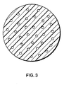
- FIGURE 3 is a transverse sectional view of an alternate embodiment of a catheter constructed in accordance with the present invention.
-
- With reference to Figures 1-3 of the drawings, an apparatus used to practice the disclosed method includes a suitable
hydraulic compressor 10 for delivering a liquid carrier (such as water) under pressure. It and anoxygen cylinder 12 are connected via suitable tubing to ahigh pressure reservoir 14 of the liquid carrier and oxygen. Afilter 16 is in fluid communication with thereservoir 14. The filter typically has a mesh size below about 1 micron and serves to remove fine solid particles from effluents emerging from thereservoir 14. After passing through avalve 18, the effluents in the form of oxygen dissolved in water are delivered under pressure to silicacapillary tubing 20 before injection into an environment of interest, such ashypoxemic blood plasma 22, via a catheter. - Also present but not depicted are suitable mechanisms for the control of temperature, pressure, and flow. I will first describe the method and then the apparatus used according to the present invention.
- In greater detail, the preferred method steps for delivering oxygen into an environment of interest, such as blood plasma, having the characteristic of low concentration of oxygen before delivery, comprises the steps of:
- 1. Prepare a mixture of oxygen and a liquid, such as water, or a 5% solution of dextrose in water (D5W);
- 2. Compress the mixture (in the high pressure reservoir 14) so that the oxygen dissolves in the liquid to form an oxygen-enriched liquid;
- 3. Deliver the oxygen-enriched liquid to a catheter having an internal diameter and length which retains at least a part of the oxygen in solution and prevents the formation of any bubbles which may emerge from the oxygen-enriched liquid upon emergence from the catheter;
- 4. Position the catheter in the blood plasma;
- 5. Inject the oxygen-enriched liquid into the oxygen-depleted environment through the catheter so that bubble formation does not occur during injection or during oxygenation of the oxygen-depleted environment.
-
- In one series of experiments, oxygen dissolved in water (or D5W or other crystalloid) at a relatively high concentration of the gas, on the order of 3-6 cc oxygen per gram of water, can be delivered into an aqueous environment with essentially no bubble formation. Oxygen from a standard
medical gas cylinder 12 was delivered to thehigh pressure reservoir 14 which contained water from thecompressor 10. Thehigh pressure reservoir 14 was isolated from thegas source 12. A piston was moved by thehydraulic compressor 10 to pressurize the water/oxygen mixture in thereservoir 14 to a pressure higher than needed to fully dissolve the gas, e.g., in the 1 kbar range for 3-6 cc oxygen per gram of water. After passing throughappropriate filters 16, the water with the dissolved oxygen then is delivered at the same high pressure (approximately 0.5 to 1 kbar) tocapillary tubing 20. - The formation of any bubbles ejected from the distal end of capillary tubing is a function of the internal diameter of the tubing. Fused silica capillary tubes (Polymicro Technology) with internal diameters ranging from 1 micron to 75 microns were tested in terms of the occurrence and size of bubbles ejected, as noted on video recordings from a light microscope.
- The most critical parameter which allows an oxygen (or other gas) bubble to disappear in an aqueous environment is its size. Bubbles on the order of 3-5 microns disappear in a small fraction of a second, an observation consistent with those in the literature concerning disappearance rates of air bubbles. For example, a 2 micron bubble may disappear in 10 msec.
- When fluid is ejected from the distal end of silica tubing drawn to 7 microns or less internal diameter over a ca. 1-30 mm length from a 30 micron internal diameter tubing, no bubbles were observable when the fluid was immersed under water, despite the fact that the oxygen content was as high as 5 cc gas/gm of water.
- These observations suggest that it should be possible with this approach to deliver oxygen via a catheter placed in the right atrium or a great vein, without any bubble formation occurring. Therefore, problems relating to bubble formation, such as foam formation, occlusion of pulmonary capillaries, etc., would be circumvented.
- In addition, it should be possible to suspend oxygen hydrate particles in initially gas-free water, without the concern for excessive hydrate decomposition or excessive diffusion of oxygen into the liquid water carrier. This is because at 0°C (or 120 bar gas pressure, which is far exceeded by the 1 kbar hydrostatic pressure), for example, a concentration of approximately 4-5 cc oxygen in liquid water represents a point on the phase diagram equilibrium line between solid hydrate and liquid saturated with gas so the tendency of hydrate to be formed is as great as that for the hydrate to decompose.
- In one experiment for delivering oxygen into blood, a hydraulic compressor (Leco/Tem-Press Div.) was used to compress a mixture of oxygen and 5% dextrose in water (D5W) in a two-headed high pressure vessel. The 27 cc internal volume of the latter was initially filled with D5W, with the exception that a small volume (1 to 3 cc's) was removed prior to closure of the vessel.
- After closure of the vessel, the distal end of the vessel was compressed with oxygen for approximately 15 seconds via a tank of the latter at a pressure of 2500 psi. The vessel was then isolated from the oxygen source. A 3 cm long stainless steel piston, fitted with either two or three O-rings, was placed at the proximal end of the high pressure vessel, so that after closure of the vessel, pressurization with oxygen, and isolation from the oxygen source, the D5W/oxygen mixture was then compressed by movement of the piston, driven by the hydraulic compressor at a pressure of 3,000 to 15,000 psi.
- After allowing 10 minutes or longer for the oxygen to dissolve in the D5W, a valve at the distal end of the vessel was opened to allow flow of the mixture through a 1/16" o.d./ 1/64" i.d. SS tubing which was connected to a hollow fused silica fiberoptic via a high pressure, low resistance filter fitted with 5 micron sintered powdered SS metal filters.
- Typically, a 30 micron or 50 micron i.d. (either 363 micron or 144 micron o.d.) hollow fused silica capillary tubing (Polymicro Technologies) was used at the distal end of the delivery system, and the silica tubing was drawn at its distal end in a propane torch to an internal diameter of 1 to 10 microns over a few millimeters of axial distance. The primary resistance to flow resided at this location, and flow was therefore governed by the geometry at this location as well as by the pressure applied.
- When the distal tip was submerged under degassed water, the remarkable finding was that no bubbles were observable for an oxygen concentration of 1 to approximately 5 cc oxygen/g D5W, when the internal diameter of the distal tip of the hollow capillary tubing was less than approximately 7 microns.
- In order to examine the effect of the infusion of the oxygen/D5W mixture on the oxygenation of blood and on blood element integrity, 20-33 cc's of citrated venous dog blood was placed in a beaker. The air above the blood was replaced with an inert gas such as helium, and the beaker was covered with paraffin. An Oximetrics oxygen saturation catheter for continuous monitoring of oxygen saturation was placed in the blood. A magnetic stirrer was used on the lowest setting to gently mix the blood, while the hollow silica capillary tubing was immersed in the blood before delivery of the oxygen/D5W mixture.
- Typically, the oxygen saturation had a baseline level of 15% to 40%. The infusion was terminated when the oxygen saturation increased to 80% or greater. In all cases, the increase in oxygen saturation was commensurate with the quantity of oxygen delivered (calculated from the measured flow rate of D5W and the oxygen content of the fluid).
- The i.d. of the capillary tubing at its distal end was measured by inspection under a light microscope coupled to video camera and color monitor at an overall magnification of approximately 1000 X. Knowledge of the flow rate and i.d. of the tubing at its distal end permitted calculation of the velocity of flow at this location. The flow velocity was then compared against measurements of free plasma hemoglobin. The latter was determined, after centrifugation of blood elements, spectrophotometrically in the plasma (supernatant) by the absorption at 572 nm (a strong absorption peak of hemoglobin). The results are consistent with findings of other investigators who have noted that marked erythrocyte hemolysis occurs at flow velocities greater than 2,000 cm/sec. When flow velocity was less than 400 cm/sec, no evidence of hemolysis was found to occur.
- Thus, it is possible to oxygenate blood without either bubble formation or erythrocyte hemolysis.
- In one embodiment of this invention, a bundle of 25 fused silica capillary tubes, with an i.d. of 105 microns and an o.d. of 144 microns per tube, was drawn in a flame so that the o.d. of the bundle was sufficiently small to place within 30 micron to 150 micron i.d. fused silica capillary tubing. The length of the bundle was only a few millimeters in each case, and the bundle was bonded to the outer capillary tubing by annealing in a flame. Each small tubing, which now had an i.d. of approximately 5 microns, provided the same small bubbles and flow rate as the system described above, and the overall flow from the outer silica tubing was simply the sum of the individual tubes. Typically, a flow rate of at least 0.01 cc/min. can be achieved through a 5-7 micron (i.d.) tubing, so that the overall flow rate from the bundle of tubes was at least 0.25 cc/min. By use of an outer tubing with an i.d. of 150 microns, approximately 280 tubes with an i.d. of 6 microns can be positioned at the distal tip, and a flow rate of greater than 2 cc/min can be achieved with the outer tubing. Additional outer tubings with the bundle of small tubes can be added to achieve and level of flow desired.
- In the relatively low oxygen yield system described above, wherein 2 to approximately 5 cc of oxygen per gram of D5W can be delivered, oxygen hydrate particles can be suspended to provide a much greater oxygen yield per gram of D5W. At an oxygen concentration of 4-5 cc oxygen/g D5W at 0°C-4°C, the concentration is sufficient to prevent any hydrate decomposition prior to exiting the capillary tubing. With the use of a Jet Pulverizer, it has been possible to grind ice to a mean particle size of 1-2 microns, and it should therefore be possible to grind a mixture of oxygen hydrate and ordinary D5W together to this same small dimension. The hydrate particles will remain solid under pressure (e.g., greater than 300 psi at 0°C), while the ordinary D5W will provide a liquid carrier for the hydrate particles. The latter should pass easily through tubing having an i.d. of 3 to 7 microns.
- The exiting stream at the distal end of the capillary tubing can be modified in many ways to enhance mixing, alter flow velocity, etc., so that uniform mixing with blood can be achieved without mechanical trauma to blood elements.
- Further experiments with a strobe light source have provided further insight into oxygenation of blood. In one experiment, a 30 cc capacity Leco high pressure vessel was filled with 5 g% dextrose in water. Then a small volume of the latter (2 to 8 cc) was removed before connecting the vessel to a source of compressed oxygen, typically a standard oxygen cylinder at 1500 to 2500 psi, for a period of approximately 15 sec. The vessel was then isolated from the oxygen source, and the contents of the vessel were compressed by a piston driven by a hydraulic compressor to a pressure of 5,000 to 15,000 psi for 15 minutes or longer.
- The high pressure forced all oxygen gas to be dissolved in the liquid, so that no bubbles were present. At the distal end of the vessel, a valve connected the latter to a high pressure sintered metal filter having an average pore size of 0.5 microns. A silica capillary tubing was mounted at its proximal end in a stainless steel capillary tube assembly which was connected to the distal end of the filter. The distal end of the capillary tubing, which had a typical internal diameter of 30 to 150 microns, had been drawn in a propane torch to an internal diameter of 2 to 25 microns. Alternatively, a 1-3 cm length of 5 micron i.d./140 micron o.d. silica tubing was epoxied within the distal end of 150 micron i.d. tubing. When the oxygenated liquid was forced through the silica capillary tubing, the greatest resistance to flow was at the distal end of this tubing, so that the pressure in the non-tapered end of the tubing was similar to that in the pressure vessel (5,000 to 15,000 psi). Because of the high resistance at the end of the silica tubing, the flow rate typically ranged from 0.002 cc to 0.05 cc per minute.
- The fluid stream which emerged from the distal end of the tubing was viewed under a light microscope at either 100 X or 400 X magnification. A 20 nanosecond, broad spectrum strobe light (Model 437B High Intensity Nanopulse System, Xenon, Inc.) "froze" the motion of the stream, estimated to have a velocity of 100 to 4000 cm/sec. Photographic recordings were made on Tmax P3200 Kodak film in a camera mounted on the microscope. The stream was observed in air, under water, and finally under plasma.
- The results of these studies demonstrated that, although bubbles were invariably present when the stream was viewed in air, as evidenced by growing droplet size, no bubbles were formed or were present in any portion of streams which were viewed under water or plasma, when the oxygen content of the liquid was approximately 5 cc per gram or less and the i.d. of the tapered distal end of the silica tubing was 7 microns or less.
- For lower oxygen concentrations, on the order of 1 to 1.5 cc per gram, a larger i.d. (<25 microns) of the tapered end of the silica capillary tubing was used with no bubble formation. Stream velocity over a 100 to 4000 cm/sec range and driving hydraulic pressure over a 2,000 to 15,000 psi range had no effect on this observation.
- Studies by other investigators (e.g., Hemmingsen E.A., Cavitation In Gas-Supersaturated Solutions, J. Applied Physics 1:213-218, 1975) have shown that water can be supersaturated to some degree with gases and, after hydraulic compression of the gas/water mixture at 0.5 to 1 kbar to dissolve all gas nuclei, a sudden release (over 2-3 seconds) of the pressure to 1 bar resulted, remarkably, in no immediate bubble formation. In the case of oxygen, the upper limit of gasification of water which did not result in bubble formation upon decompression was found to be approximately 140 psi, which corresponds to a gas concentration of about 4.2 cc oxygen per gram of water, and higher concentrations were achievable at temperatures below 3°C. If the fluid after decompression was disturbed in some manner, such as shaking or heating, bubble formation ensued.
- When water is hydraulically compressed to 0.5 to 1.0 kbar, all bubbles and nuclei are forced to dissolve, and spontaneous bubble formation then requires that the molecular structure of water needs to be disrupted. When previous investigators attempted to explain why a greater gas concentration was not achievable without spontaneous cavitation upon release to 1 bar, it was felt that small density or thermal gradients in water allowed a small collection of gas molecules (a minimum of 10,000 gas molecules is thought to be necessary to overcome the surface tension of water at very small dimensions) to form. Once formed, rapid growth would then occur by diffusion from the water phase.
- By analogy, it appears than, when 5 g% dextrose in water is supersaturated with oxygen to a concentration of approximately 5 cc per gram or less, stability of the gasified fluid is maintained despite ejection through a tubing, as long as the internal diameter of the tubing is sufficiently small. The present work demonstrates that supersaturated fluids can be subjected to 1 bar and movement at the above velocities without spontaneous cavitation, i.e., bubble formation, occurring. Why larger tubings result in bubble formation is unknown, but it is quite possible that density and thermal gradients within water are magnified, compared to smaller tubings, between different sites of a given cross-section of the flow field.
- To summarize, I have shown that an oxygen supersaturated solution of 5 g% dextrose in water can be injected into water or plasma with no bubble formation. Although the oxygen content of this approach is limited to approximately 5 cc per gram, the oxygen content can be greatly increased by adding particles of a gas hydrate, such as oxygen hydrate particles. The latter should be completely stable, at 0°C and >120 bar pressure, since the concentration of oxygen required in the liquid phase under equilibrium conditions is approximately 5 cc per gram. The hydrate particles, if sufficiently small (e.g., 1-3 microns in diameter), would produce short-lived bubbles upon ejection into blood and decomposition, while the liquid phase would produce no bubbles. In theory, a maximal oxygen content of as high as 100 cc per gram of injectate could be achieved with a 2:1 suspension of hydrate: water (D5W).
- Regional infusion of fluids supersaturated with oxygen into specific vascular spaces has utility even in the absence of hypoxemia.
- Intraluminal infusion of oxygen-supersaturated crystalloids, such as 5 g % dextrose in water, into arterial blood which is already saturated with oxygen can be used to supersaturate blood without foam formation. Other techniques for enhancement of regional oxygen perfusion such as the use of hydrogen peroxide produce foam during decomposition into oxygen and water upon contact with tissue catalase: Foam formation blocks blood flow.
- In a variety of clinical settings, regional infusion of oxygen-supersaturated crystalloids to supersaturate blood would be expected to have a beneficial response. For example, in patients with either acute myocardial infarction or a cerebrovascular accident, local infusion of the oxygen-supersaturated fluid directly into a coronary artery or a carotid artery would greatly enhance delivery of oxygen to ischemic tissue. The greater the oxygen content of blood, the greater will be the ability of plasma compared to red blood cells to perfuse ischemic tissue.
- By analogy, placement of patients, suffering from either of these conditions, in a hyperbaric oxygen chamber reduces tissue ischemia more effectively than simply breathing oxygen at 1 bar. The resultant high partial pressures of oxygen as well as the high oxygen content of arterial blood into which the oxygen-enriched fluid is infused would simulate the beneficial effects of hyperbaric oxygen. The potential systemic toxicity, particularly pulmonary toxicity, would be avoided by the local intra-arterial infusion.
- Regional intravascular infusion of oxygen-enriched crystalloids into tumors would also be expected to enhance the efficacy of radiation therapy, since oxygen radicals produced during the latter form the basis for subsequent tumor necrosis. There are undoubtedly many more examples of the potential utility of regional intravascular infusion of oxygen-enriched crystalloids, including enhancement of tissue responses to photodynamic therapy (e.g., hemotoporphyrin derivative, phthalocyanines, purpurins, etc.); treatment of myocardial failure with prolonged infusions; and potential treatment of chronic lesions such as tumors and atheromatous plaques which may resolve over a prolonged period of infusion as a result, for example, of improved oxidative catabolic activity of tissue macrophages.
Claims (14)
- A method of preparing oxygen for delivery into an environment of interest wherein the method is carried out outside the human or animal body characterized by the steps of:preparing a mixture of oxygen and a liquid;compressing the mixture so that the oxygen dissolves in the liquid to form an oxygen-enriched liquid; anddelivering the oxygen-enriched liquid to tubing (20) having an internal diameter and length which retains the oxygen in solution and prevents formation of bubbles in the oxygen-enriched liquid.
- A method as claimed in claim 1, wherein the liquid is water or a physiologic crystalloid solution.
- A method as claimed in claim 1 or 2, wherein the step of compressing the mixture comprises applying a pressure of about 0.5 to 1 kbar.
- A method as claimed in any one of the preceding claims, wherein the tubing has an internal diameter between 1-250 microns in size.
- A method as claimed in any one of the preceding claims, wherein the step of delivering the oxygen-enriched liquid to the tubing (20) comprises injecting the oxygen-enriched liquid into the tubing without any bubble formation so that no foam is formed.
- A method as claimed in any one of the preceding claims, wherein the liquid is plasma.
- A method as claimed in any one of the preceding claims, in which the tubing (20) is a catheter.
- An apparatus for delivering oxygen into an environment of interest, such as blood plasma (22), the apparatus including a catheter (20) and
one or more high pressure tubings, each of which incudes a distal end having one or more channels, characterized in that each channel has an internal diameter of 1-10 microns over a few millimeters to a few centimeters of axial distance, so that a primary resistance to flow resides at the distal end. - An apparatus as claimed in claim 8, wherein the catheter (20) comprises a bundle of fused silica tubes at the distal end of the catheter (20).
- An apparatus as claimed in claim 9, wherein the bundle of channels of the distal end of the catheter (20) comprises hollow carbon fibers, having an internal diameter of approximately 5 microns and external diameter of approximately 10 microns.
- An apparatus as claimed in claim 9 or 10, wherein each tube in the bundle of tubes provides a liquid flow rate of at least .001cc per minute under 1 kbar of pressure, each tube in the bundle having an internal diameter of 5 microns - 7 microns so that the overall flow rate of the bundle of tubes is at least 0.1 cc per minute of oxygen delivered into the blood.
- An apparatus as claimed in any one of claims 9 to 11, wherein the bundle comprises approximately 280 tubes, each with an internal diameter of 6 microns so that a liquid flow rate > 2 cc's per minute is achieved.
- An apparatus as claimed in any one of claims 8 to 12, wherein the high pressure tubing is comprised of metal tubing.
- An apparatus as claimed in any one of claims 8 to 13, wherein the high pressure tubing is comprised of silica capillary tubing.
Applications Claiming Priority (3)
| Application Number | Priority Date | Filing Date | Title |
|---|---|---|---|
| US152589 | 1993-11-15 | ||
| US08/152,589 US5407426A (en) | 1991-02-14 | 1993-11-15 | Method and apparatus for delivering oxygen into blood |
| PCT/US1994/012815 WO1995013843A1 (en) | 1993-11-15 | 1994-11-07 | Method and apparatus for delivering oxygen into blood |
Publications (3)
| Publication Number | Publication Date |
|---|---|
| EP0729369A1 EP0729369A1 (en) | 1996-09-04 |
| EP0729369A4 EP0729369A4 (en) | 1999-02-24 |
| EP0729369B1 true EP0729369B1 (en) | 2003-10-22 |
Family
ID=22543556
Family Applications (1)
| Application Number | Title | Priority Date | Filing Date |
|---|---|---|---|
| EP95901806A Expired - Lifetime EP0729369B1 (en) | 1993-11-15 | 1994-11-07 | Method and apparatus for delivering oxygen |
Country Status (8)
| Country | Link |
|---|---|
| US (1) | US5407426A (en) |
| EP (1) | EP0729369B1 (en) |
| JP (1) | JP3620849B2 (en) |
| AU (1) | AU1090595A (en) |
| CA (1) | CA2176601A1 (en) |
| DE (1) | DE69433265T2 (en) |
| ES (1) | ES2208671T3 (en) |
| WO (1) | WO1995013843A1 (en) |
Families Citing this family (47)
| Publication number | Priority date | Publication date | Assignee | Title |
|---|---|---|---|---|
| US5730935A (en) * | 1984-07-12 | 1998-03-24 | Wayne State University | High pressure gas exchanger |
| US5599296A (en) * | 1991-02-14 | 1997-02-04 | Wayne State University | Apparatus and method of delivery of gas-supersaturated liquids |
| USRE37379E1 (en) | 1991-02-14 | 2001-09-18 | Wayne State University | High pressure gas exchanger |
| US6344489B1 (en) * | 1991-02-14 | 2002-02-05 | Wayne State University | Stabilized gas-enriched and gas-supersaturated liquids |
| US5569180A (en) * | 1991-02-14 | 1996-10-29 | Wayne State University | Method for delivering a gas-supersaturated fluid to a gas-depleted site and use thereof |
| US5693017A (en) * | 1991-02-14 | 1997-12-02 | Wayne State University | Apparatus and method of delivery of gas-supersaturated solutions to a delivery site |
| US6315942B1 (en) | 1993-11-15 | 2001-11-13 | Wayne State University | System for delivery of gas-enriched fluids |
| US6180059B1 (en) * | 1995-06-05 | 2001-01-30 | Therox, Inc. | Method for the preparation and delivery of gas-enriched fluids |
| US6312647B1 (en) | 1994-12-09 | 2001-11-06 | Wayne State University | Method for enriching a fluid with oxygen |
| US6607698B1 (en) | 1997-08-15 | 2003-08-19 | Therox, Inc. | Method for generalized extracorporeal support |
| US6676900B1 (en) | 1994-12-09 | 2004-01-13 | Therox, Inc. | Method for the preparation and delivery of gas-enriched fluids |
| US6235007B1 (en) | 1995-11-27 | 2001-05-22 | Therox, Inc. | Atraumatic fluid delivery devices |
| US5834519A (en) * | 1996-10-11 | 1998-11-10 | Wayne State University | Stabilized gas-supersaturated emulsions and suspensions |
| US20040099523A1 (en) * | 1996-12-04 | 2004-05-27 | Otec Research Inc. | Catalytic simulation using radio frequency waves |
| US5879282A (en) | 1997-01-21 | 1999-03-09 | Cordis A Johnson And Johnson Company | Catheter having an expandable radioactive source |
| AU7467098A (en) * | 1997-04-16 | 1998-11-11 | Wayne State University | System and method for delivery of gas-supersaturated fluids |
| EP0887076A3 (en) * | 1997-05-07 | 1999-03-31 | Saturnus A.G. | Adhesion prevention and an endoscopic insufflation system therefor |
| US5893838A (en) * | 1997-08-15 | 1999-04-13 | Therox, Inc. | System and method for high pressure delivery of gas-supersaturated fluids |
| US5971368A (en) * | 1997-10-29 | 1999-10-26 | Fsi International, Inc. | System to increase the quantity of dissolved gas in a liquid and to maintain the increased quantity of dissolved gas in the liquid until utilized |
| US6527979B2 (en) * | 1999-08-27 | 2003-03-04 | Corazon Technologies, Inc. | Catheter systems and methods for their use in the treatment of calcified vascular occlusions |
| US6394096B1 (en) | 1998-07-15 | 2002-05-28 | Corazon Technologies, Inc. | Method and apparatus for treatment of cardiovascular tissue mineralization |
| WO2000004943A1 (en) * | 1998-07-24 | 2000-02-03 | Therox, Inc. | Method and apparatus for the preparation and delivery of gas-enriched fluids |
| US6602467B1 (en) | 1998-07-24 | 2003-08-05 | Therox, Inc. | Apparatus and method for blood oxygenation |
| US6759008B1 (en) | 1999-09-30 | 2004-07-06 | Therox, Inc. | Apparatus and method for blood oxygenation |
| DE60031706T2 (en) | 1999-09-30 | 2007-09-06 | Therox, Inc., Irvine | DEVICE FOR BLOOD OXYGENATION |
| US6387324B1 (en) | 1999-09-30 | 2002-05-14 | Therox, Inc. | Apparatus and method for blood oxygenation |
| US6890482B2 (en) | 1999-09-30 | 2005-05-10 | Therox, Inc. | Apparatus for blood oxygenation |
| US6694977B1 (en) * | 1999-10-01 | 2004-02-24 | Critical Care Research, Inc. | Mixed-mode liquid ventilation gas and heat exchange |
| US6585679B1 (en) * | 1999-10-21 | 2003-07-01 | Retinalabs.Com | System and method for enhancing oxygen content of infusion/irrigation fluid for ophthalmic surgery |
| US7008535B1 (en) | 2000-08-04 | 2006-03-07 | Wayne State University | Apparatus for oxygenating wastewater |
| US6613280B2 (en) * | 2001-03-20 | 2003-09-02 | Therox, Inc. | Disposable cartridge for producing gas-enriched fluids |
| US6582387B2 (en) | 2001-03-20 | 2003-06-24 | Therox, Inc. | System for enriching a bodily fluid with a gas |
| DE102004052254A1 (en) * | 2004-05-03 | 2005-12-01 | Plasmid Factory Gmbh & Co. Kg | Process for disrupting cells and separating cell components |
| EP1928557B1 (en) | 2005-08-23 | 2018-06-06 | The Regents of The University of California | Reflux resistant cannula and system for chronic delivery of therapeutic agents using convection-enhanced delivery |
| US20080057023A1 (en) * | 2006-08-29 | 2008-03-06 | Chynn Emil W | Oxygenated ophthalmic composition |
| US9101711B2 (en) * | 2007-10-07 | 2015-08-11 | Chi-Wei Tao | Intravascular nano-bubbling oxygenator |
| US20090098017A1 (en) * | 2007-10-16 | 2009-04-16 | Board Of Regents, The University Of Texas System | Nanoporous membrane exchanger |
| US8192384B2 (en) | 2008-12-04 | 2012-06-05 | Therox, Inc. | System for enriching a bodily fluid with a gas having a dual-function power switch mechanism |
| US8636952B2 (en) | 2008-12-04 | 2014-01-28 | Therox, Inc. | System for enriching a bodily fluid with a gas having a removable gas-enrichment device with an information recording element |
| US8246564B2 (en) | 2008-12-04 | 2012-08-21 | Therox, Inc. | System for enriching a bodily fluid with a gas having automated priming capabilities |
| US8500104B2 (en) | 2010-06-07 | 2013-08-06 | James Richard Spears | Pressurized liquid stream with dissolved gas |
| WO2012096912A1 (en) | 2011-01-14 | 2012-07-19 | Children's Hospital Los Angeles | Solution of carbon monoxide for treatment of disease, including sickle cell disease |
| US9919276B2 (en) | 2012-05-01 | 2018-03-20 | Therox, Inc. | System and method for bubble-free gas-enrichment of a flowing liquid within a conduit |
| US9295393B2 (en) | 2012-11-09 | 2016-03-29 | Elwha Llc | Embolism deflector |
| US10173030B2 (en) | 2013-11-15 | 2019-01-08 | Oakwood Healthcare, Inc. | Catheter for infusion of a cardiovascular fluid |
| US9724460B2 (en) | 2014-03-25 | 2017-08-08 | Oakwood Healthcare, Inc. | Controlled nucleation from gas-supersaturated liquid |
| WO2022187859A1 (en) * | 2021-03-05 | 2022-09-09 | Regents Of The University Of Minnesota | Intravenous delivery of large volumes of gas with highly pressurized supersaturated solution |
Citations (1)
| Publication number | Priority date | Publication date | Assignee | Title |
|---|---|---|---|---|
| EP0489496A1 (en) * | 1990-11-08 | 1992-06-10 | Possis Medical, Inc. | Water jet atherectomy device |
Family Cites Families (8)
| Publication number | Priority date | Publication date | Assignee | Title |
|---|---|---|---|---|
| US4657532A (en) * | 1985-07-19 | 1987-04-14 | Thomas Jefferson University | Intra-peritoneal perfusion of oxygenated fluorocarbon |
| US4450841A (en) * | 1982-03-03 | 1984-05-29 | Thomas Jefferson University | Stroke treatment utilizing extravascular circulation of oxygenated synthetic nutrients to treat tissue hypoxic and ischemic disorders |
| US5086620A (en) * | 1991-02-14 | 1992-02-11 | Wayne State University | Method of microencapsulation of hyperbaric gas |
| US5261875A (en) * | 1991-02-14 | 1993-11-16 | Wayne State University | Method and apparatus for injection of gas hydrates |
| US4986809A (en) * | 1989-04-17 | 1991-01-22 | Hattler Brack G | Percutaneous oxygenator |
| US5098376A (en) * | 1989-12-22 | 1992-03-24 | Cardiopulmonics, Inc. | Apparatus and methods for furling and introducing an extrapulmonary blood gas exchange device |
| US5219326A (en) * | 1991-03-27 | 1993-06-15 | Hattler Brack G | Inflatable percutaneous oxygenator |
| US5072739A (en) * | 1991-06-05 | 1991-12-17 | John Angelo P | Ischemia-reperfusion tumor therapy |
-
1993
- 1993-11-15 US US08/152,589 patent/US5407426A/en not_active Expired - Lifetime
-
1994
- 1994-11-07 ES ES95901806T patent/ES2208671T3/en not_active Expired - Lifetime
- 1994-11-07 JP JP51448495A patent/JP3620849B2/en not_active Expired - Fee Related
- 1994-11-07 CA CA002176601A patent/CA2176601A1/en not_active Abandoned
- 1994-11-07 WO PCT/US1994/012815 patent/WO1995013843A1/en not_active Ceased
- 1994-11-07 AU AU10905/95A patent/AU1090595A/en not_active Abandoned
- 1994-11-07 DE DE69433265T patent/DE69433265T2/en not_active Expired - Lifetime
- 1994-11-07 EP EP95901806A patent/EP0729369B1/en not_active Expired - Lifetime
Patent Citations (1)
| Publication number | Priority date | Publication date | Assignee | Title |
|---|---|---|---|---|
| EP0489496A1 (en) * | 1990-11-08 | 1992-06-10 | Possis Medical, Inc. | Water jet atherectomy device |
Also Published As
| Publication number | Publication date |
|---|---|
| EP0729369A4 (en) | 1999-02-24 |
| ES2208671T3 (en) | 2004-06-16 |
| JP3620849B2 (en) | 2005-02-16 |
| DE69433265D1 (en) | 2003-11-27 |
| DE69433265T2 (en) | 2004-07-15 |
| CA2176601A1 (en) | 1995-05-26 |
| US5407426A (en) | 1995-04-18 |
| EP0729369A1 (en) | 1996-09-04 |
| WO1995013843A1 (en) | 1995-05-26 |
| AU1090595A (en) | 1995-06-06 |
| JPH09509072A (en) | 1997-09-16 |
Similar Documents
| Publication | Publication Date | Title |
|---|---|---|
| US5407426A (en) | Method and apparatus for delivering oxygen into blood | |
| US6312647B1 (en) | Method for enriching a fluid with oxygen | |
| US5599296A (en) | Apparatus and method of delivery of gas-supersaturated liquids | |
| JP3712729B2 (en) | Method for delivering gas supersaturated fluid to gas deficient zone and its use | |
| JP5502927B2 (en) | Blood oxygenation apparatus and method | |
| US6180059B1 (en) | Method for the preparation and delivery of gas-enriched fluids | |
| US6849235B2 (en) | Method of forming gas-enriched fluid | |
| US6454997B1 (en) | Apparatus for the preparation and delivery of gas-enriched fluids | |
| US20030215356A1 (en) | Method of blood oxygenation | |
| JPH11506645A (en) | Delivery of oxygen supersaturated physiological solution | |
| US20250032691A1 (en) | Devices And Methods To Infuse Gases Into And Out Of Blood | |
| EP1100560A1 (en) | Method and apparatus for the preparation and delivery of gas-enriched fluids |
Legal Events
| Date | Code | Title | Description |
|---|---|---|---|
| PUAI | Public reference made under article 153(3) epc to a published international application that has entered the european phase |
Free format text: ORIGINAL CODE: 0009012 |
|
| 17P | Request for examination filed |
Effective date: 19960606 |
|
| AK | Designated contracting states |
Kind code of ref document: A1 Designated state(s): DE ES FR GB IT |
|
| A4 | Supplementary search report drawn up and despatched |
Effective date: 19990105 |
|
| AK | Designated contracting states |
Kind code of ref document: A4 Designated state(s): DE ES FR GB IT |
|
| 17Q | First examination report despatched |
Effective date: 20001215 |
|
| RTI1 | Title (correction) |
Free format text: METHOD AND APPARATUS FOR DELIVERING OXYGEN |
|
| RTI1 | Title (correction) |
Free format text: METHOD AND APPARATUS FOR DELIVERING OXYGEN |
|
| GRAH | Despatch of communication of intention to grant a patent |
Free format text: ORIGINAL CODE: EPIDOS IGRA |
|
| RTI1 | Title (correction) |
Free format text: METHOD AND APPARATUS FOR DELIVERING OXYGEN |
|
| GRAS | Grant fee paid |
Free format text: ORIGINAL CODE: EPIDOSNIGR3 |
|
| GRAA | (expected) grant |
Free format text: ORIGINAL CODE: 0009210 |
|
| AK | Designated contracting states |
Kind code of ref document: B1 Designated state(s): DE ES FR GB IT |
|
| REG | Reference to a national code |
Ref country code: GB Ref legal event code: FG4D |
|
| REF | Corresponds to: |
Ref document number: 69433265 Country of ref document: DE Date of ref document: 20031127 Kind code of ref document: P |
|
| ET | Fr: translation filed | ||
| REG | Reference to a national code |
Ref country code: ES Ref legal event code: FG2A Ref document number: 2208671 Country of ref document: ES Kind code of ref document: T3 |
|
| PLBE | No opposition filed within time limit |
Free format text: ORIGINAL CODE: 0009261 |
|
| STAA | Information on the status of an ep patent application or granted ep patent |
Free format text: STATUS: NO OPPOSITION FILED WITHIN TIME LIMIT |
|
| 26N | No opposition filed |
Effective date: 20040723 |
|
| PGFP | Annual fee paid to national office [announced via postgrant information from national office to epo] |
Ref country code: DE Payment date: 20101126 Year of fee payment: 17 |
|
| PGFP | Annual fee paid to national office [announced via postgrant information from national office to epo] |
Ref country code: GB Payment date: 20101124 Year of fee payment: 17 Ref country code: IT Payment date: 20101124 Year of fee payment: 17 |
|
| PGFP | Annual fee paid to national office [announced via postgrant information from national office to epo] |
Ref country code: FR Payment date: 20111128 Year of fee payment: 18 Ref country code: ES Payment date: 20111124 Year of fee payment: 18 |
|
| GBPC | Gb: european patent ceased through non-payment of renewal fee |
Effective date: 20121107 |
|
| REG | Reference to a national code |
Ref country code: FR Ref legal event code: ST Effective date: 20130731 |
|
| PG25 | Lapsed in a contracting state [announced via postgrant information from national office to epo] |
Ref country code: IT Free format text: LAPSE BECAUSE OF NON-PAYMENT OF DUE FEES Effective date: 20121107 |
|
| REG | Reference to a national code |
Ref country code: DE Ref legal event code: R119 Ref document number: 69433265 Country of ref document: DE Effective date: 20130601 |
|
| PG25 | Lapsed in a contracting state [announced via postgrant information from national office to epo] |
Ref country code: DE Free format text: LAPSE BECAUSE OF NON-PAYMENT OF DUE FEES Effective date: 20130601 |
|
| PG25 | Lapsed in a contracting state [announced via postgrant information from national office to epo] |
Ref country code: FR Free format text: LAPSE BECAUSE OF NON-PAYMENT OF DUE FEES Effective date: 20121130 Ref country code: GB Free format text: LAPSE BECAUSE OF NON-PAYMENT OF DUE FEES Effective date: 20121107 |
|
| REG | Reference to a national code |
Ref country code: ES Ref legal event code: FD2A Effective date: 20140304 |
|
| PG25 | Lapsed in a contracting state [announced via postgrant information from national office to epo] |
Ref country code: ES Free format text: LAPSE BECAUSE OF NON-PAYMENT OF DUE FEES Effective date: 20121108 |