EP0726992B1 - Improved roof tile - Google Patents
Improved roof tile Download PDFInfo
- Publication number
- EP0726992B1 EP0726992B1 EP94900114A EP94900114A EP0726992B1 EP 0726992 B1 EP0726992 B1 EP 0726992B1 EP 94900114 A EP94900114 A EP 94900114A EP 94900114 A EP94900114 A EP 94900114A EP 0726992 B1 EP0726992 B1 EP 0726992B1
- Authority
- EP
- European Patent Office
- Prior art keywords
- tiles
- tile
- roof
- central portion
- front edge
- Prior art date
- Legal status (The legal status is an assumption and is not a legal conclusion. Google has not performed a legal analysis and makes no representation as to the accuracy of the status listed.)
- Expired - Lifetime
Links
- 230000000007 visual effect Effects 0.000 claims description 2
- 239000004570 mortar (masonry) Substances 0.000 description 3
- 239000000203 mixture Substances 0.000 description 2
- 239000012615 aggregate Substances 0.000 description 1
- 239000004568 cement Substances 0.000 description 1
- 239000004927 clay Substances 0.000 description 1
- 230000000295 complement effect Effects 0.000 description 1
- 230000000694 effects Effects 0.000 description 1
- 238000004519 manufacturing process Methods 0.000 description 1
- 238000012986 modification Methods 0.000 description 1
- 230000004048 modification Effects 0.000 description 1
- 239000000049 pigment Substances 0.000 description 1
- 238000007493 shaping process Methods 0.000 description 1
Images

Classifications
-
- E—FIXED CONSTRUCTIONS
- E04—BUILDING
- E04D—ROOF COVERINGS; SKY-LIGHTS; GUTTERS; ROOF-WORKING TOOLS
- E04D1/00—Roof covering by making use of tiles, slates, shingles, or other small roofing elements
- E04D1/02—Grooved or vaulted roofing elements
- E04D1/04—Grooved or vaulted roofing elements of ceramics, glass or concrete, with or without reinforcement
Definitions
- This invention is concerned with improvements in or relating to a roof tile and particularly this invention is concerned with improvements in or relating to contoured interlocking roof tiles.
- a roof tile having a profiled upper surface, for example, a double Roman, a bold roll or similar tile.
- Such a tile generally comprises profiled side portions on each side of a profiled central portion with the side portions being provided with upwardly or downwardly facing channels respectively for facilitating, in use, the interlocking of each tile with sideways adjacent tiles on a roof.
- the front edge thickness of most interlocking concrete roof tiles is governed by the minimum thickness required for the interlock at the longitudinal edges of the tiles.
- the thickness of the interlock portion of the tile is maintained across the tile so that the depth of a front edge surface thereof, i.e. that surface facing downwardly of a roof, in use, is constant or substantially so.
- roof tile dictates that an unnecessary proportion of the tile weight is evident in the thick front edge portion of the tile which thick front edge portion adds little if any structural value to the tile and has a principal aim of closing any gaps which might otherwise be evident between overlapped tail and headlap portions of tiles laid on a roof.
- the present invention seeks to mitigate or overcome the shortcomings of known tiles and involves a roof tile with a profiled upper surface and a front edge surface, which front edge surface extends across the width of the tile and faces downwardly of a roof in use, wherein the front edge surface is of progressively greater depth as between a relatively thin profiled central portion and thicker profiled side portions thereof.
- Prior art document FR-A-1097530 describes tiles having a front edge surface which is progressively greater depth as between a relatively thin profiled central portion and thicker profiled side portions. However, this prior art document describes tiles which can only be laid in full bond relationship. Prior art document DE-C-16814 describes tiles with a thickness in cross-section which varies across their width; however, these tiles do not have a profiled upper suface. Neither of these prior art documents disclose the features of the present invention.
- the present invention therefore provides a tile comprising a raised central portion, a raised interlocking side portion at each side of said tile and a valley portion between each side portion and said central portion, said tile having a front edge surface which extends across the width of said tile and faces downwardly of a roof in use, characterised in that said front edge surface is of a depth which becomes progressively greater between a relatively thin section coincident with said central portion, and relatively thicker sections adjacent to said interlocking side portions.
- the invention provides a tile wherein the front edge surface of the tile varies in depth across the width of the tile as between a relatively thin section coincident with said central portion, deeper sections coincident with said valley portions and sections of intermediate depth coincident with said interlocking side portions.
- the invention provides a tile wherein, in use, the depth of the front edge surface in the area of the valley portions is less than the combined thickness of the interlocked side portions of mutually sideways adjacent tiles in use.
- the depth of the front edge surface in the area of the valley porions thereof approximates to one-half the combined depths of the front edge surface at the relatively thin section coincident with the central portion and the sections of intermediate depth coincident with the interlocked side portions of mutually sideways adjacent tiles in use.
- the central portion is relatively thin as aforesaid for at least one-third of the length of the tile and more especially the central portion is relatively thin as aforesaid for the full length of the tile.
- the present invention also conveniently provides a tile wherein the raised central portion thereof comprises an upper profile generated along the length thereof wherein an apex of said upper profile lies below a corresponding apex of a similar profile generated by the interlocked side portions of mutually sideways adjacent tiles in use.
- tiles according to the present invention may comprise a bold roll or a double Roman profile of roof tile.
- the present invention still further provides a roof covered with roof tiles according to any one of the last seven preceding paragraphs wherein, in use, each horizontal row of tiles is laid in half-bond relationship with adjacent horizontal rows of such tiles and wherein the combined overlapped thicknesses of the tiles in one such row of tiles and the tiles of adjacent rows of tiles thereabove and/or therebelow at overlapped headlap and tail portions thereof are the same or substantially so.
- the visual appearance of the roof is one in which a constant thickness is evident at the valley portions of the tiles of each column of tiles on the roof whereas the roll portions thereof have a thick-thin, thick-thin appearance both in sideways adjacent columns of such tiles and in each individual column thereof.
- the front edge thicknesses of conventional concrete roofing tiles result from having relatively thick, i.e. deep, sidelock portions the depth of which is maintained across the front edge portion of a tile to prevent gapping as between superimposed tiles on a roof. Prudent reduction of the front edge thicknesses of a tile provides a lighter product with consequent savings of cement, aggregate and pigment utilised for the composition from which the tile is manufactured.
- the present invention provides an interlocking contoured roof tile 10, i.e. a "bold roll” type of tile, see Figure 1.
- the tile 10 is generally rectangular in plan and comprises left and right hand profiled interlocking side portions 12 and 14 respectively.
- the portion 12 is provided on an underside 16 thereof, see Figures 1 and 2, with longitudinally extending ribs 18 and 20 and channels 22 and 24 while the portion 14 is provided on an upperside 26 thereof with complementary ribs 28 and 30 and channels 32 and 34.
- the ribs and channels enable the mutual interlock of like tiles on a roof in use.
- the tile 10 also comprises a profiled central portion 36 an apex 38 of which lies substantially below a corresponding apex 40 of the portion 12, see especially Figure 2.
- the tile 10 further comprises a front edge surface 44 which varies in depth across the width of the tile as between a relatively thin section portion 46 coincident with the central portion 36, deeper sections 48 and 50 coincident with said valley portions 41 and 42 and side face portions 52 and 54 of intermediate depth adjacent to said interlocking side portions 12 and 14 respectively.
- the depth of the portion 46 reflects the thin section portion 36 which may be relatively thin for all of its length along the tile 10 or for a proportion of such length, say one-third thereof.
- the depths of the sections 48 and 50 are such that each is one-half the depth of a thin section portion 46 plus the combined depth of interlocked side portions 12 and 14 of a tile, see Figure 2, where it is evident that in use the depth of two superimposed valley portions 40 and 42 is equal, or substantially so, to the combined depth of a thin section portion 46 and the interlock side portions 12 and 14.
- the tiles 10 of the present invention may be formed by the well established concrete roof tile processing route wherein tile mortar provided to a hopper is constrained to pass under a shaping roller and slipper to emerge as a ribbon of tile mortar on a series of identical tile pallets with the tile shape and thickness being dictated by gaps provided between the upper surfaces of the pallets and the undersides of the shaped rollers and slippers.
- the ribbon of mortar so formed is thereafter cut to form discrete tiles on the pallets.
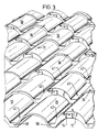
- the tiles can only be assembled, i.e. laid, on a roof in half-bond relationship, see Figures 2 and 3; however, the effect is startlingly attractive in that while the in-line valley portions of the tiles are of uniform thickness the roll portions of the tiles both up and across the roof have a thick-thin, thick-thin appearance.
- tiles according to the invention may be made from clay or any other suitable composition.
Landscapes
- Engineering & Computer Science (AREA)
- Chemical & Material Sciences (AREA)
- Ceramic Engineering (AREA)
- Architecture (AREA)
- Civil Engineering (AREA)
- Structural Engineering (AREA)
- Devices For Post-Treatments, Processing, Supply, Discharge, And Other Processes (AREA)
- Inorganic Insulating Materials (AREA)
- Insulation, Fastening Of Motor, Generator Windings (AREA)
- Roof Covering Using Slabs Or Stiff Sheets (AREA)
- Resistance Heating (AREA)
- Buildings Adapted To Withstand Abnormal External Influences (AREA)
- Finishing Walls (AREA)
- Panels For Use In Building Construction (AREA)
Abstract
Description
characterised in that said front edge surface is of a depth which becomes progressively greater between a relatively thin section coincident with said central portion, and relatively thicker sections adjacent to said interlocking side portions.
Claims (10)
- A roof tile (10) comprising a raised central portion (36), a raised interlocking side portion (12, 14) at each side of said tile and a valley portion (48, 50) between each side portion (12, 14) and said central portion (36), said tile having a front edge surface (44) which extends across the width of said tile and faces downwardly of a roof in use,
characterised in that
said front edge surface (44) is of a depth which becomes progressively greater between a relatively thin section (46) coincident with said central portion (36), and relatively thicker sections (52, 54) adjacent to said interlocking side portions (12, 14). - A tile according to Claim 1 wherein the front edge surface (44) of the tile varies in depth across the width of the tile as between a relatively thin section (46) coincident with said central portion (36), deeper sections (48,50) coincident with said valley portions (41,42) and sections of intermediate depth coincident with said interlocking side portions (12,14).
- A tile according to claim 2 wherein, in use, the depth of the front edge surface (44) in the area of valley portions (48,50) is less than the combined thickness of the interlocked side portions (12,14) of mutually sideways adjacent tiles in use.
- A tile according to Claim 2 wherein the depth of the front edge surface (44) in the area of the valley portions (48, 50) approximates to one-half the combined depths of the front edge surface at the relatively thin section 46) coincident with the central portion (36) and the sections of intermediate depth coincident with the interlocked side portions (12, 14)of mutually sideways adjacent tiles in use.
- A tile according to any one of Claims 1, 2, 3 or 4 wherein the central portion (36) is relatively thin as aforesaid for at least one-third of the length of the tile.
- A tile according to Claim 5 wherein the central portion (36) is relatively thin as aforesaid for the full length of the tile.
- A tile according to Claim 6 wherein the raised central portion (36) thereof comprises an upper profile generated along the length thereof wherein an apex (38) of said upper profile lies below a corresponding apex (40) of a similar profile generated by the interlocked side portions (12, 14) of mutually sideways adjacent tiles in use.
- A tile according tc Claim 7 which comprises a bold roll or double Roman profile tile.
- A roof covered with roof tiles according to any one of Claims 1 to 8 wherein, in use, each horizontal row of tiles is laid in half-bond relationship with adjacent horizontal rows of such tiles and wherein the combined overlapped thicknesses of the tiles in one such row of tiles and the tiles of adjacent rows of tiles thereabove and/or therebelow at overlapped headlap and tail portions thereof are the same or substantially so.
- A roof according to Claim 9 wherein the visual appearance of the roof is one in which a constant thickness is evident at the valley portions of the tiles of each column of tiles on the roof whereas the roll portions thereof have a thick-thin, thick-thin appearance both in sideways adjacent columns of such tiles and in each individual column thereof.
Applications Claiming Priority (2)
| Application Number | Priority Date | Filing Date | Title |
|---|---|---|---|
| GB9209771A GB2266903B (en) | 1992-05-06 | 1992-05-06 | Improved roof tile |
| PCT/EP1993/003124 WO1995013441A1 (en) | 1992-05-06 | 1993-11-08 | Improved roof tile |
Publications (2)
| Publication Number | Publication Date |
|---|---|
| EP0726992A1 EP0726992A1 (en) | 1996-08-21 |
| EP0726992B1 true EP0726992B1 (en) | 1999-01-13 |
Family
ID=26070079
Family Applications (1)
| Application Number | Title | Priority Date | Filing Date |
|---|---|---|---|
| EP94900114A Expired - Lifetime EP0726992B1 (en) | 1992-05-06 | 1993-11-08 | Improved roof tile |
Country Status (9)
| Country | Link |
|---|---|
| US (1) | US5941039A (en) |
| EP (1) | EP0726992B1 (en) |
| JP (1) | JPH09506146A (en) |
| AT (1) | ATE175747T1 (en) |
| AU (1) | AU685404B2 (en) |
| DE (1) | DE69323099T2 (en) |
| GB (1) | GB2266903B (en) |
| NZ (1) | NZ257844A (en) |
| WO (1) | WO1995013441A1 (en) |
Families Citing this family (24)
| Publication number | Priority date | Publication date | Assignee | Title |
|---|---|---|---|---|
| GB2266903B (en) * | 1992-05-06 | 1995-05-31 | Redland Eng Ltd | Improved roof tile |
| US5928796A (en) * | 1994-10-21 | 1999-07-27 | Elisha Technologies Co Llc | Corrosion resistant coatings containing an amorphous phase |
| US5714093A (en) * | 1994-10-21 | 1998-02-03 | Elisha Technologies Co. L.L.C. | Corrosion resistant buffer system for metal products |
| US6080334A (en) * | 1994-10-21 | 2000-06-27 | Elisha Technologies Co Llc | Corrosion resistant buffer system for metal products |
| JPH10509469A (en) * | 1994-10-21 | 1998-09-14 | エリシャ・テクノロジーズ・カンパニー・エルエルシー | Corrosion resistance buffer system for metal products |
| US5938976A (en) * | 1994-10-21 | 1999-08-17 | Elisha Technologies Co. L.L.C. | Corrosion resistant coatings containing an amorphous phase |
| DE19612490C1 (en) * | 1996-03-29 | 1997-09-18 | Braas Gmbh | Lower deck element for a flat plate-shaped component |
| EP1234924A1 (en) * | 2001-02-27 | 2002-08-28 | Gambale Srl | Double curved tile with anti-sliding fixing |
| FR2829165B1 (en) * | 2001-08-31 | 2005-02-18 | Frederic Wild | MONOBLOCK AND MODULAR ELEMENTS OF LONGITUDINAL SHAPE, MOLDS, IMITATING THE APPEARANCE OF A VERTICAL TILE ROW, AND ASSEMBLING TO REALIZE A ROOF COVER |
| ITBO20030625A1 (en) * | 2003-10-23 | 2005-04-24 | Gambale Srl | "COPPO WITH GREATER AND WIND-HOLDING CAPACITY". |
| USD579126S1 (en) * | 2005-02-04 | 2008-10-21 | Mattingly Ricky D | Panel with repeating convex arcuate pattern for wall or ceiling |
| USD589634S1 (en) * | 2005-02-04 | 2009-03-31 | Mattingly Ricky D | Panel with repeating concave arcuate pattern for wall or ceiling |
| GB2424426A (en) * | 2005-03-22 | 2006-09-27 | Lafarge Roofing Technical Centers Ltd | Insulated roof system |
| EP1931841A1 (en) * | 2005-10-07 | 2008-06-18 | Damon Stone | Concrete tile system and method of manufacture |
| DE102005050657B3 (en) * | 2005-10-20 | 2007-01-11 | Lafarge Roofing Technical Centers Gmbh | Roofing tile comprises water barriers made from elastic plates in the region of a water course |
| USD562994S1 (en) * | 2007-03-15 | 2008-02-26 | Boral Lifetile Inc. | Roof tile |
| USD562993S1 (en) | 2007-03-15 | 2008-02-26 | Boral Lifetile Inc | Roof tile |
| USD602611S1 (en) | 2008-04-14 | 2009-10-20 | Monier Technical Centre Ltd. | S-type roof tile |
| USD628878S1 (en) | 2008-05-22 | 2010-12-14 | Lincoln Global, Inc. | Enclosure edge assembly |
| US20100237157A1 (en) * | 2009-03-21 | 2010-09-23 | Zhaojun Guo | Ground heating flooring with internal heating conduction structure |
| USD613428S1 (en) | 2009-03-27 | 2010-04-06 | Monier, Inc. | Roof tile |
| DE102015102530A1 (en) * | 2015-02-23 | 2016-08-25 | Monier Roofing Gmbh | Dachstein and method of making such a Dachstein |
| USD827874S1 (en) * | 2017-01-15 | 2018-09-04 | Wencon Development, Inc. | Double bowed replacement tile |
| US10508448B2 (en) | 2017-09-11 | 2019-12-17 | Lala Khajani | Tile and method of production |
Family Cites Families (14)
| Publication number | Priority date | Publication date | Assignee | Title |
|---|---|---|---|---|
| DE16814C (en) * | F. MEYER in Schweringen, Amt Hoya | Innovations in roof tiles | ||
| CH6429A (en) * | 1893-03-21 | 1893-08-15 | Oscar Standow | New roof interlocking tile |
| US651873A (en) * | 1900-03-13 | 1900-06-19 | Wilhelm Ludowici | Gutter-tile. |
| US746747A (en) * | 1902-10-24 | 1903-12-15 | Carl Schlachter | Roofing-tile. |
| FR678706A (en) * | 1929-07-18 | 1930-04-03 | Tile refinements | |
| FR766840A (en) * | 1933-01-23 | 1934-07-04 | Tonwarenindustrie Wiesloch Ag | Protective Rib Tile |
| CH194695A (en) * | 1937-02-25 | 1937-12-31 | Josef Schneider Joh | Interlocking roof tiles. |
| FR1087801A (en) * | 1952-05-27 | 1955-03-01 | Miter tile | |
| FR1097530A (en) * | 1954-04-02 | 1955-07-06 | Tuileries De Narbonne | Tile refinements |
| BE794604A (en) * | 1972-01-28 | 1973-05-16 | Gerhaher Max | MECHANICAL OR THREADED TILE |
| DE3030819A1 (en) * | 1980-08-12 | 1982-02-25 | Betona AG, Glarus | Rainproof profiled concrete roof tile - has outward rising inclined longitudinal fold and rounded bottom rib ridges |
| DE3708281A1 (en) * | 1987-03-13 | 1988-09-22 | Martin Pehl | Interlocking roofing tile |
| US5048255A (en) * | 1990-02-12 | 1991-09-17 | Gonzales Arthur S | Molded thermoplastic roofing tile |
| GB2266903B (en) * | 1992-05-06 | 1995-05-31 | Redland Eng Ltd | Improved roof tile |
-
1992
- 1992-05-06 GB GB9209771A patent/GB2266903B/en not_active Expired - Fee Related
-
1993
- 1993-11-08 JP JP7513546A patent/JPH09506146A/en active Pending
- 1993-11-08 US US08/640,763 patent/US5941039A/en not_active Expired - Lifetime
- 1993-11-08 AT AT94900114T patent/ATE175747T1/en not_active IP Right Cessation
- 1993-11-08 WO PCT/EP1993/003124 patent/WO1995013441A1/en not_active Ceased
- 1993-11-08 DE DE69323099T patent/DE69323099T2/en not_active Expired - Fee Related
- 1993-11-08 NZ NZ257844A patent/NZ257844A/en unknown
- 1993-11-08 EP EP94900114A patent/EP0726992B1/en not_active Expired - Lifetime
- 1993-11-08 AU AU54645/94A patent/AU685404B2/en not_active Ceased
Also Published As
| Publication number | Publication date |
|---|---|
| AU685404B2 (en) | 1998-01-22 |
| NZ257844A (en) | 1998-01-26 |
| ATE175747T1 (en) | 1999-01-15 |
| DE69323099T2 (en) | 1999-07-01 |
| AU5464594A (en) | 1995-05-29 |
| GB9209771D0 (en) | 1992-06-17 |
| WO1995013441A1 (en) | 1995-05-18 |
| JPH09506146A (en) | 1997-06-17 |
| DE69323099D1 (en) | 1999-02-25 |
| GB2266903A (en) | 1993-11-17 |
| US5941039A (en) | 1999-08-24 |
| EP0726992A1 (en) | 1996-08-21 |
| GB2266903B (en) | 1995-05-31 |
Similar Documents
| Publication | Publication Date | Title |
|---|---|---|
| US5941039A (en) | Roof tile | |
| EP0175500B1 (en) | Improvements in roof tiles | |
| CA1306117C (en) | Concrete roof tiles | |
| US5502940A (en) | Composite building element and methods of making and using the same | |
| US2269926A (en) | Composite board flooring | |
| WO1997028328A1 (en) | Thickened reinforced roofing shingle | |
| HUP9901996A2 (en) | Floor covering, consisting of hard floor panels and method for manufacturing such floor panels | |
| NZ204103A (en) | Building panel simulating shingles:tapered end segments for ship lap jointing | |
| US2269927A (en) | Composite floor and floor unit for forming the same | |
| CN217480717U (en) | Terrazzo stone-like brick | |
| US6235142B1 (en) | Method of producing laminated shingle | |
| US5620278A (en) | Tile | |
| CA2032948A1 (en) | Slab lining | |
| CN1075151C (en) | Improved Roof Tiles | |
| JPH07238640A (en) | Roofing structure of corner tile | |
| AU2004100460A4 (en) | Improved Sheeting | |
| MY110764A (en) | Improved roof tile | |
| IE61782B1 (en) | Roof tiles | |
| GB2191226A (en) | Interlocking roofing slate | |
| NZ195960A (en) | Tiled roof: staggered tiles and double battening | |
| CN2575216Y (en) | Multilayer angle beadings | |
| IES83491Y1 (en) | Interlocking roof tile | |
| JPH05321409A (en) | Roofing tile | |
| DE1105135B (en) | Multi-layer parquet floor board | |
| IE83539B1 (en) | Tile |
Legal Events
| Date | Code | Title | Description |
|---|---|---|---|
| PUAI | Public reference made under article 153(3) epc to a published international application that has entered the european phase |
Free format text: ORIGINAL CODE: 0009012 |
|
| 17P | Request for examination filed |
Effective date: 19960528 |
|
| AK | Designated contracting states |
Kind code of ref document: A1 Designated state(s): AT BE DE DK ES FR GB IE IT NL PT SE |
|
| GRAG | Despatch of communication of intention to grant |
Free format text: ORIGINAL CODE: EPIDOS AGRA |
|
| GRAG | Despatch of communication of intention to grant |
Free format text: ORIGINAL CODE: EPIDOS AGRA |
|
| GRAH | Despatch of communication of intention to grant a patent |
Free format text: ORIGINAL CODE: EPIDOS IGRA |
|
| 17Q | First examination report despatched |
Effective date: 19980415 |
|
| GRAH | Despatch of communication of intention to grant a patent |
Free format text: ORIGINAL CODE: EPIDOS IGRA |
|
| GRAA | (expected) grant |
Free format text: ORIGINAL CODE: 0009210 |
|
| AK | Designated contracting states |
Kind code of ref document: B1 Designated state(s): AT BE DE DK ES FR GB IE IT NL PT SE |
|
| PG25 | Lapsed in a contracting state [announced via postgrant information from national office to epo] |
Ref country code: IT Free format text: LAPSE BECAUSE OF FAILURE TO SUBMIT A TRANSLATION OF THE DESCRIPTION OR TO PAY THE FEE WITHIN THE PRE;WARNING: LAPSES OF ITALIAN PATENTS WITH EFFECTIVE DATE BEFORE 2007 MAY HAVE OCCURRED AT ANY TIME BEFORE 2007. THE CORRECT EFFECTIVE DATE MAY BE DIFFERENT FROM THE ONE RECORDED.SCRIBED TIME-LIMIT Effective date: 19990113 Ref country code: ES Free format text: THE PATENT HAS BEEN ANNULLED BY A DECISION OF A NATIONAL AUTHORITY Effective date: 19990113 |
|
| REF | Corresponds to: |
Ref document number: 175747 Country of ref document: AT Date of ref document: 19990115 Kind code of ref document: T |
|
| REG | Reference to a national code |
Ref country code: IE Ref legal event code: FG4D |
|
| REF | Corresponds to: |
Ref document number: 69323099 Country of ref document: DE Date of ref document: 19990225 |
|
| PG25 | Lapsed in a contracting state [announced via postgrant information from national office to epo] |
Ref country code: PT Free format text: LAPSE BECAUSE OF FAILURE TO SUBMIT A TRANSLATION OF THE DESCRIPTION OR TO PAY THE FEE WITHIN THE PRESCRIBED TIME-LIMIT Effective date: 19990413 Ref country code: DK Free format text: LAPSE BECAUSE OF FAILURE TO SUBMIT A TRANSLATION OF THE DESCRIPTION OR TO PAY THE FEE WITHIN THE PRESCRIBED TIME-LIMIT Effective date: 19990413 |
|
| ET | Fr: translation filed | ||
| NLT1 | Nl: modifications of names registered in virtue of documents presented to the patent office pursuant to art. 16 a, paragraph 1 |
Owner name: LAFARGE BRAAS RESEARCH AND DEVELOPMENT LIMITED;RBB |
|
| RAP2 | Party data changed (patent owner data changed or rights of a patent transferred) |
Owner name: LAFARGE BRAAS RESEARCH AND DEVELOPMENT LIMITED |
|
| PG25 | Lapsed in a contracting state [announced via postgrant information from national office to epo] |
Ref country code: IE Free format text: LAPSE BECAUSE OF NON-PAYMENT OF DUE FEES Effective date: 19991108 |
|
| PLBE | No opposition filed within time limit |
Free format text: ORIGINAL CODE: 0009261 |
|
| STAA | Information on the status of an ep patent application or granted ep patent |
Free format text: STATUS: NO OPPOSITION FILED WITHIN TIME LIMIT |
|
| PGFP | Annual fee paid to national office [announced via postgrant information from national office to epo] |
Ref country code: BE Payment date: 19991122 Year of fee payment: 7 |
|
| BECN | Be: change of holder's name |
Effective date: 19990908 |
|
| 26N | No opposition filed | ||
| REG | Reference to a national code |
Ref country code: IE Ref legal event code: MM4A |
|
| PG25 | Lapsed in a contracting state [announced via postgrant information from national office to epo] |
Ref country code: BE Free format text: LAPSE BECAUSE OF NON-PAYMENT OF DUE FEES Effective date: 20001130 |
|
| BERE | Be: lapsed |
Owner name: LAFARGE BRAAS RESEARCH & DEVELOPMENT LTD Effective date: 20001130 |
|
| PGFP | Annual fee paid to national office [announced via postgrant information from national office to epo] |
Ref country code: GB Payment date: 20011022 Year of fee payment: 9 |
|
| PGFP | Annual fee paid to national office [announced via postgrant information from national office to epo] |
Ref country code: SE Payment date: 20011121 Year of fee payment: 9 |
|
| PGFP | Annual fee paid to national office [announced via postgrant information from national office to epo] |
Ref country code: FR Payment date: 20011122 Year of fee payment: 9 |
|
| PGFP | Annual fee paid to national office [announced via postgrant information from national office to epo] |
Ref country code: AT Payment date: 20011123 Year of fee payment: 9 |
|
| PGFP | Annual fee paid to national office [announced via postgrant information from national office to epo] |
Ref country code: NL Payment date: 20011127 Year of fee payment: 9 |
|
| PGFP | Annual fee paid to national office [announced via postgrant information from national office to epo] |
Ref country code: DE Payment date: 20011211 Year of fee payment: 9 |
|
| REG | Reference to a national code |
Ref country code: GB Ref legal event code: IF02 |
|
| PG25 | Lapsed in a contracting state [announced via postgrant information from national office to epo] |
Ref country code: GB Free format text: LAPSE BECAUSE OF NON-PAYMENT OF DUE FEES Effective date: 20021108 Ref country code: AT Free format text: LAPSE BECAUSE OF NON-PAYMENT OF DUE FEES Effective date: 20021108 |
|
| PG25 | Lapsed in a contracting state [announced via postgrant information from national office to epo] |
Ref country code: SE Free format text: LAPSE BECAUSE OF NON-PAYMENT OF DUE FEES Effective date: 20021109 |
|
| PG25 | Lapsed in a contracting state [announced via postgrant information from national office to epo] |
Ref country code: NL Free format text: LAPSE BECAUSE OF NON-PAYMENT OF DUE FEES Effective date: 20030601 |
|
| PG25 | Lapsed in a contracting state [announced via postgrant information from national office to epo] |
Ref country code: DE Free format text: LAPSE BECAUSE OF NON-PAYMENT OF DUE FEES Effective date: 20030603 |
|
| GBPC | Gb: european patent ceased through non-payment of renewal fee | ||
| EUG | Se: european patent has lapsed | ||
| PG25 | Lapsed in a contracting state [announced via postgrant information from national office to epo] |
Ref country code: FR Free format text: LAPSE BECAUSE OF NON-PAYMENT OF DUE FEES Effective date: 20030731 |
|
| NLV4 | Nl: lapsed or anulled due to non-payment of the annual fee |
Effective date: 20030601 |
|
| REG | Reference to a national code |
Ref country code: FR Ref legal event code: ST |