EP0726496B1 - Photographic film processing apparatus - Google Patents
Photographic film processing apparatus Download PDFInfo
- Publication number
- EP0726496B1 EP0726496B1 EP96101660A EP96101660A EP0726496B1 EP 0726496 B1 EP0726496 B1 EP 0726496B1 EP 96101660 A EP96101660 A EP 96101660A EP 96101660 A EP96101660 A EP 96101660A EP 0726496 B1 EP0726496 B1 EP 0726496B1
- Authority
- EP
- European Patent Office
- Prior art keywords
- film
- exposing
- photographic film
- processing apparatus
- transport
- Prior art date
- Legal status (The legal status is an assumption and is not a legal conclusion. Google has not performed a legal analysis and makes no representation as to the accuracy of the status listed.)
- Expired - Lifetime
Links
Images


Classifications
-
- G—PHYSICS
- G03—PHOTOGRAPHY; CINEMATOGRAPHY; ANALOGOUS TECHNIQUES USING WAVES OTHER THAN OPTICAL WAVES; ELECTROGRAPHY; HOLOGRAPHY
- G03D—APPARATUS FOR PROCESSING EXPOSED PHOTOGRAPHIC MATERIALS; ACCESSORIES THEREFOR
- G03D3/00—Liquid processing apparatus involving immersion; Washing apparatus involving immersion
- G03D3/08—Liquid processing apparatus involving immersion; Washing apparatus involving immersion having progressive mechanical movement of exposed material
-
- G—PHYSICS
- G03—PHOTOGRAPHY; CINEMATOGRAPHY; ANALOGOUS TECHNIQUES USING WAVES OTHER THAN OPTICAL WAVES; ELECTROGRAPHY; HOLOGRAPHY
- G03D—APPARATUS FOR PROCESSING EXPOSED PHOTOGRAPHIC MATERIALS; ACCESSORIES THEREFOR
- G03D15/00—Apparatus for treating processed material
- G03D15/04—Cutting; Splicing
- G03D15/043—Cutting or splicing of filmstrips
- G03D15/046—Automatic cutting
-
- Y—GENERAL TAGGING OF NEW TECHNOLOGICAL DEVELOPMENTS; GENERAL TAGGING OF CROSS-SECTIONAL TECHNOLOGIES SPANNING OVER SEVERAL SECTIONS OF THE IPC; TECHNICAL SUBJECTS COVERED BY FORMER USPC CROSS-REFERENCE ART COLLECTIONS [XRACs] AND DIGESTS
- Y10—TECHNICAL SUBJECTS COVERED BY FORMER USPC
- Y10T—TECHNICAL SUBJECTS COVERED BY FORMER US CLASSIFICATION
- Y10T83/00—Cutting
- Y10T83/525—Operation controlled by detector means responsive to work
- Y10T83/533—With photo-electric work-sensing means
Definitions
- the present invention relates to a photographic film processing apparatus for processing a long developed photographic film formed by joining a plurality of films with a splicing material.
- the developed photographic film taken up in a roll is subjected to a printing process by an automatic printing unit.
- the long film is passed through the printing process and taken up in a roll again, and subsequently the film is cut order by order by a cutting deviced.
- a method for separating such joined photographic films subsequent to the exposing and printing process is known from US-A-5 373 339, in which the splice adhesive between two films is heated until it softens and subsequently the two films are pulled in opposite direction in order to separate them from each other. Additionally, a splice pick-up web is provided for removing the splices.
- Developed photographic film such as an ordinary 135 film, for example, may be a film with full-size or panorama-size frames 36mm long each, or a film with half-size frames 17mm long each.
- a long photographic film includes panorama-size and half-size films
- the long film is subjected to a printing process and taken up in a roll, while printing only the full-size film first, skipping the panorama-size and half-size films.
- the panorama-size and half-size films are printed, and the long film is cut for respective orders.
- film in one order has a mixture of full-size and panorama-size films
- the full-size film is printed first, and then the panorama-size film, followed by a cutting process.
- US-A-4 319 946 discloses an apparatus for automatically classifying and reorganizing a processed long length of films prior to the exposing and printing process, the films being connected together having different frame sizes into lengths of films each having the same frame size.
- the apparatus comprises a cutter for cutting the spliced portions of films, a classification and reorganizing means for forming the classified and cut films into lengths of films each having the same frame size and a splicer for splicing the films with corresponding sizes into one long length.
- this method is very complicated, since the joined films have to be separated from each other, reorganized and again joined together.
- the object of the present invention is to provide a photographic film processing apparatus for carrying out various exposing processes including a printing process efficiently and speedily even for a long developed photographic film formed by joining a plurality of films with a splicing material.
- a main cutter cuts the long developed film into short films prior to an exposing process, and a second transport device transports the short films to an exposure processing unit.
- the long film is cut into short films corresponding to respective orders from clients. These short films are transported to the exposure processing unit.
- the short films having special image frames such as panorama-size or half-size frames are excluded once before reaching the exposure processing unit.
- Those short films having only full-size image frames are transported to the exposure processing units.
- an appropriate measure may be taken to omit an exposing process for the short films having special size image frames.
- This apparatus avoids the complicated practice of the prior art. That is, in the prior art, films in a long spliced film having only full-size image frames are processed by the exposure processing units and the long film is taken up in a roll. Then films having special size frames are processed by the exposure processing units. Thereafter the long film is cut order by order.
- the apparatus according to the present invention carries out various exposing processes efficiently as a whole.
- the exposure processing units can cope with the full size and panorama size of the same image frame length, only half-size films having a different image frame length may be excluded. Where the exposure processing unit can cope with full size and half size, only the panorama size films may be excluded.
- the long photographic film could include films unfit for an exposing process because of an extreme degree of overexposure or underexposure. An appropriate measure may be taken to exclude such films.
- a loop storing device is disposed on a transport line formed by the first transport device and the second transport device for storing the long developed film in loop form.
- a discharge device is interposed between the main cutter and the exposure processing unit for discharging film fragments cut by the main cutter from a transport line formed by the first transport device and the second transport device.
- a film propriety distinguishing device is disposed on a transport line formed by the first transport device and the second transport device for determining whether the short films are fit for processing by the exposure processing unit.
- the film propriety distinguishing device distinguishes, without requiring observation by the operator, image frames of special lengths mixed into the long developed photographic film or presence of films having overexposed image frames, for example. This automatic distinguishing operation realizes improved efficiency and reliable results of distinguishment.
- the processing apparatus may further comprise a process averting device for averting, from processing by the exposure processing unit, those of the short films determined by the film propriety distinguishing device to be unfit.
- the process averting device defines a branch line for branching the short films determined to be unfit from the transport line.
- a simple additional construction consisting of the branch line enables an automatic removal of unfit photographic films before reaching the exposure processing units, to smooth the processing by the exposure processing unit.
- the discharge device defines a discharge passage extending downward from the transport line for guiding cut film fragments including small fragments from film regions adjacent the splicing material and a large fragment including a film leader connected to a forward end of the long developed film, the discharge passage including a partition mounted in an intermediate position thereof for allowing passage of only the small fragments and deflecting the large fragment.
- the leader is larger than the fragments cut from the region of the splicing material in the photographic film. Utilizing this fact, the leader may be collected separately from the fragments cut from the splice region of the photographic film by the simple construction consisting of the partition disposed in an intermediate position of the discharge passage.
- the partition may be disposed in such a position that the large fragment is transported by the transport line until a forward end of the film leader reaches the partition. Then, the leader advancing through the discharge passage is controlled with respect to position and inclination transversely of the advancing direction. Thus, the leader is restrained from shifting or inclining to varied extents transversely of the advancing direction, thereby to realize reliable sorting of the leader.
- the discharge device includes a branching opening defined in a side wall of the discharge passage above the partition for allowing passage of the large fragment. This opening is provided in order to separate the leader positionally and clearly from the small fragments which are to be discarded, so that the leader may be recovered, with priority, for reuse.
- the discharge device may include a movable guide disposed in a region of intersection between the transport line and the discharge passage to be switchable between a posture for guiding the short films to advance along the transport line and a posture for guiding the film fragments cut by the main cutter into the discharge passage.
- the processing apparatus in a preferred embodiment further comprises an auxiliary cutter for cutting lateral portions of the region of the splicing material in the long developed film.
- the auxiliary cutter when the main cutter is operated to cut the long photographic film in the region of the splicing material to a short film corresponding to each order, for example, the auxiliary cutter may also be operated to cut lateral portions of the region of the splicing material. Consequently, any portions of the film protruding laterally of the region of the splicing material may be removed as otherwise such portions could obstruct a subsequent transporting process.
- the splicing material remaining attached to one of the short films includes data relating to that short film to facilitate subsequent film processing.
- a reading device may be mounted on the transport line for reading the data from the splicing material and outputting contents of the data. It is particularly advantageous if the data is stored in a film identifying bar code printed on the splicing material.
- the auxiliary cutter is operable to cut the region of the splicing material such that a width at a forward end of an upstream one of the short films is contained within a width of the downstream one of the short films.
- the forward end of the upstream film is completely contained within the width at the rear end of the downstream film. Consequently, the forward end of the upstream film remaining connected to the splicing material after cutting the long film is positively prevented from obstructing the transport.
- the main cutter and the auxiliary cutter are integrated. Then, the two cutters may share components and controls to reduce cost. This provides a further advantage of requiring reduced space.
- auxiliary cutter may be formed separately from the main cutter. This allows the auxiliary cutter to be added to an existing apparatus or to be offered as an option.
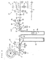
- Fig. 1 shows an automatic exposing and printing apparatus to which the photographic film processing apparatus according to the present invention is applied.
- the exposing and printing apparatus contains an image information reading unit 20 and an exposing and printing unit 30 which will be described later.
- Image information on developed negative film 10 wound on a reel 1 is read by the reading unit 20 and shown on a display 2. Based on the information shown, the operator operates a keyboard 3 to cause the exposing and printing unit 30 to expose printing paper in a proper amount of exposure. After a subsequent printing process, finished prints are discharged to a print collector 4.
- the reel 1 has, wound thereon, developed photographic film 10 in a plurality of orders from clients.
- film 10 as used in this specification has two meanings. One meaning is short developed photographic films 10a included in the orders from clients. The other meaning is a long photographic film 10b formed by successively connecting the rear end 11 of each short developed film 10a in one order to the forward end 12 of another short developed film 10a with a splicing tape 13 which is one example of joining materials (see Fig. 4).
- the long film 10b may be cut order by order again prior to an exposing and printing process, as necessary.
- the short films made by cutting the long film 10b are also referred to herein as short films 10a.
- the long film 10b has a leader 15, which itself is well known, connected to the forward end thereof.
- a dancer 5 is disposed adjacent a support axis of the reel 1 for eliminating a slack of photographic film 10.
- a film transport device 40 extends from the reel 1 toward the image information reading unit 20 and exposing and printing unit 30, which are examples of exposure processing units, for transporting the photographic film 10, more particularly the long film 10b, wound on the reel 1.
- the film transport device 40 includes a first transport portion 40a and a second transport portion 40b.
- the first transport portion 40a includes a first drive roller 42 driven by a pulse motor 41, two idle rollers 43 in contact with the first drive roller 42, a second drive roller 45 driven by a DC motor 44, an idle roller 46 in contact with the second drive roller 45, a direction changing idle roller 47, and a pair of idle roller 48 in contact with each other, for transporting the photographic film 10 toward the image information reading unit 20.
- a film cutting device 6 described in detail later is disposed on the transport line of the first transport portion 40a.
- the film cutting device 6 cuts the long film 10b into short films 10a each corresponding to one order, and cuts off part of the film.
- the second transport portion 40b of the transport device 40 transports the short films 10a from the film cutting device 6 to the image information reading unit 20.
- the second transport portion 40b includes a third drive roller 49a, an idle roller 49b, and a pair of idle rollers 49c.
- a plurality of sensors are arranged along the transport line of the transport device 40. These sensors include, for example, a film sensor 81 disposed upstream of the first drive roller 42 for detecting the photographic film 10, and an end sensor 82 disposed downstream of the first drive roller 42 for detecting splice regions of the photographic film 10 joined with the splicing tape 13, i.e. for detecting rear ends 11, forward ends 12 or splicing tapes 13. Each of these sensors 81 and 82 is formed of a light emitter and a light receiver.
- the image frame distinguishing device 83 Downstream of the end sensor 82 and upstream of the film cutting device 6 is an image frame distinguishing device 83 which is one example of film propriety distinguishing devices for determining whether or not the photographic film 10 in each order is fit for processing by the exposing and printing unit 30.
- the image frame distinguishing device 83 includes two image frame sensors 83a and 83b each formed of a light emitter and a light receiver, for detecting image frames on the photographic film 10 based on the quantities of light received after being transmitted through the film 10, and determining lengths of the respective image frames on the film 10.
- the image frame distinguishing device 83 based on frame edge detection signals, measures longitudinal and transverse dimensions of the image frames in each order to determine whether the image frames are full size, panorama size or half size.
- a discharge device 7 is disposed downstream of the film cutting device 6 for removing film portions adjacent the leader 15 and splicing tapes 13 cut by the cutting device 6 from the transport line.
- the discharge device 7 includes a trash box 50 disposed below the transport line, a pivotable guide 50a defining a slit for allowing passage of the film, and a solenoid, not shown, for driving the guide 50a.
- the guide 50a is movable between a posture extending along the transport line, as shown in solid lines in Fig. 2, for guiding the film 10, and a posture crossing the transport line, as shown in phantom lines, for guiding cut film fragments into the trash box 50.
- the trash box 50 substantially is a rectangular parallelepiped with an open top.
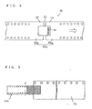
- a discharge passage 51 of rectangular cross section is formed below the transport line.
- the discharge passage 51 has a width, as seen in the moving direction of the leader 15, corresponding to or slightly larger than the width of the leader 15, so that the leader 15 in descent may remain substantially in the same posture.
- the leader 15 shown in Fig. 5 has a larger width than the film 10. The above is applicable also where a leader having the same width as the film 10 is used.
- a partition 52 is formed in an intermediate position of the discharge passage 51 for allowing passage of small fragments of the film 10 cut from adjacent the splicing tapes 13 but prohibiting passage of the leader 15.
- the partition 52 is in the form of a plate extending parallel to the film transport line and mounted in vertical posture right under a transversely middle position of the transport line. As shown in Fig. 6, the partition 52 defines a downwardly curved upper edge for contacting the leader 15. The curved edge has a lowermost point disposed adjacent an opening 53 described hereunder, to guide the leader 15 smoothly.
- the opening 53 is formed directly above the partition 52 for passing the leader 15.
- the trash box 50 is vertically divided into two parts in a position slightly above the opening 53, the lower part being detachably attached to the upper part. This construction facilitates disposal of the film fragments collected in the lower part.
- a loop tank 8 is disposed downstream of the discharge device 7.
- the loop tank 8 defines a loop storing space 8a for storing the photographic film 10 in loop form.
- An open/close loop guide 8b is disposed in an opening of the loop tank 8, which is driven by a DC motor not shown.
- a forward end sensor 84 Downstream of the loop tank 8 and second drive roller 45 is a forward end sensor 84 including a light emitter and a light receiver for detecting the forward end of the photographic film 10. Downstream of the forward end sensor 84 is a transport line branching device 90 acting as a process averting device for passing, without being processed by the image information reading unit 20 and exposing and printing unit 30, photographic film 10 in each order determined unfit by the image frame distinguishing device 83.
- the transport line branching device 90 branches the photographic film 10 in each order determined unfit, off the second transport portion 40a of the transport device 40.
- the branching device 90 includes a through passage 91 acting as a branch line extending obliquely upward through a frame disposed on the transport line of the transport device 40, a line switching element 93 pivotably attached to an axis 92 inside the through passage 91, and a solenoid 94 for driving the line switching element 93.
- a fourth drive roller 96 driven by a DC motor 95 is disposed adjacent a terminal end of the through passage 91.
- the axis 92 supports an idle roller 97 in contact with the fourth drive roller 96.
- a first rear end sensor 85 and a second rear end sensor 86 are arranged along the transport line of the transport device 40 upstream and downstream of the through passage 91, respectively, for detecting the rear end of the photographic film 10.
- the image information reading unit 20 and exposing and printing unit 30 are arranged in the stated order downstream of the transport line branching device 90.
- the image information reading unit 20 and exposing and printing unit 30 both have known constructions.
- the image information reading unit 20 includes a lamp 21, a mirror barrel 22 and an image pickup 23.
- the exposing and printing unit 30 includes an exposure lamp 31, adjusting filters 32, a mirror barrel 33, optics 34 and a shutter 35 for enlarging and printing the images of the photographic film 10 on printing paper 9.
- the film cutting device 6 includes a main cutter 60 and an auxiliary cutter 70.
- the main cutter 60 cuts the long film 10b along a transverse cutting line "k", as shown in Fig. 8A, at the forward end of each succeeding short film 10a, so that the splicing tape 13 remains on the rear end 11 of the preceding short film 10a.
- the auxiliary cutter 70 cuts, along arcuate cutting lines "m" as shown in Fig. 8B, the rear end 11 of the preceding film 10a and the forward end 12 of the succeeding film 10a at opposite lateral regions across the splicing tape 13.
- An order in which the main cutter 60 and auxiliary cutter 70 are operated to cut the long film 10b may be determined according to limitations such as an arrangement of the cutters.
- the present invention is not limited to a particular order.
- the auxiliary cutter 70 is operated first to cut off the opposite sides of the film, and then the main cutter 60 is operated to cut transversely of the film.
- the main cutter 60 includes a vertically movable upper blade 61 extending across the film transport line, and a lower blade 62 fixed on the transport line.
- the film is cut at the cutting line "k" shown in Fig. 8A.
- the leader 15 is cut off at cutting line "j" shown in Fig. 5.
- the auxiliary cutter 70 includes a pair of vertically movable upper blades 71a and 71b arranged at opposite sides of the film transport line, and a pair of right and left lower blades 72a and 72b fixed on the transport line.
- the short films 10a may be interconnected such that the rear end 11 of the preceding film 10a and the forward end 12 of the succeeding film 10a are staggered sideways (a maximum amount of displacement may be guessed from experience).
- the arcuate cuts noted above are made to such an extent that the width of the forward end 12 remaining attached to the splicing tape 13 after the cutting operations of the main cutter 60 and auxiliary cutter 70 is contained within the width of the preceding film 10a.
- the auxiliary cutter 70 has a specific construction as shown in Figs. 10A and 10B.
- the upper blades 71a and 71b are secured to a lift block 73 fixed to a lift pin 74.
- the lift pin 74 has an upper cam follower 75 and a lower cam follower 76 spaced from each other.
- An eccentric cam 77 is disposed in a space between the upper cam follower 75 and lower cam follower 76 to be rotatable by a motor 78.
- a frame 79 is provided for supporting the lift block 73 and guiding the lift pin 74.
- the eccentric cam 77 in rotation contacts the upper cam follower 75 and/or the lower cam follower 76 to raise the lift pin 74, and thus the upper blades 71a and 71b.
- the main cutter 60 has substantially the same construction as the auxiliary cutter 70, and will not be described. Naturally, other types of raising and lowering mechanism may be employed, and the present invention is not limited to a particular type.
- the lower blades 62 and 72 may be formed together, and the shape of the eccentric cam may be devised to share the motor 78. Such integration will contribute to reduced cost.
- the splicing tape 13 is allowed to remain on each preceding short film 10a when the cutting device 6 is operated to cut the long film 10b into short films 10a for respective orders.
- the splicing tape 13 includes ID information, preferably in the form of a bar code 14, printed thereon for identifying the preceding film 10a.
- the splicing tape 13 is retained in order to use this information in subsequent processing of this film 10a.
- the pulse motor 41 is operated to rotate the first drive roller 42 to transport the long film 10b, and the solenoid of the discharge device 7 is operated to swing the guide 50a to the state shown in phantom lines in Fig. 2.
- the main cutter 60 When, in this state, the end sensor 82 detects a joint in the long film 10b, the main cutter 60 is operated to cut off unwanted parts of the long film 10b such as the forward end and the leader 15. At this time, the forward end and the leader 15 of the long film 10b are guided by the guide 50a to extend downward. Thus, the unwanted, cut parts fall into the trash box 50. Subsequently, the guide 50a is returned to the state shown in solid lines in Fig. 2. The long film 10b with the forward end cut off advances through the slit formed in the guide 50a to the second drive roller 45. The second drive roller 45 advances the long film 10b further on to the forward end sensor 84.
- the first drive roller 42 continues rotating to transport the long film 10b. Consequently, as shown in Fig. 3, the long film 10b slacks downward to form a loop inside the loop storing space 8a.
- the end sensor 82 detects a next joint
- the first drive roller 42 is stopped rotating.
- the auxiliary cutter 70 is operated to cut off opposite film portions laterally of the splicing tape 13 at the cutting lines "m" in Fig. 8B.
- the main cutter 60 is operated to cut the film at the cutting line "k" in Fig. 8A. This results in the photographic film 10a in one order cut with the corresponding splicing tape 13 remaining attached thereto.
- the bar code 14 printed on the splicing tape 13 is read by a bar cord reading sensor 87 disposed in a suitable position on the transport line, to be used in subsequent film processing.
- the second drive roller 45 is rotated again to transport the photographic film 10a in this one order.
- the loop guide 8b is swung back to the position to close the loop tank 8.
- the photographic film 10a in one order cut off the long film 10b has already been checked by the image frame distinguishing device 83 whether or not the film 10a is fit for processing by the exposing and printing unit 30. That is, it has been determined whether the image frames on this film 10a are full size or panorama size suited to the exposing and printing unit 30, or half size not suited thereto. If the frames have the sizes suited to the exposing and printing unit 30, the film 10a is transported to the image information reading unit 20 at the next stage. Necessary information is read and shown on the display 2. Subsequently, the exposing and printing unit 30 prints the image frames on the printing paper 9. At a point of time the rear end of the photographic film 10a passes the second rear end sensor 86, the first drive roller 42 is driven again to repeat the same operation.
- the solenoid 94 is operated to drive the line switching element 93.
- the line switching element 93 guides the film 10a into the through passage 91.
- the DC motor 95 is operated to rotate the fourth drive roller 96 to discharge the film 10a from the transport line.
- the first drive roller 42 is driven to repeat the same operation.
- the foregoing embodiment includes the image information reading unit 20 and exposing and printing unit 30 as examples of exposure processing units. These exposure processing units include all processing units needed to expose and print the images of photographic film on printing paper.
- image frame distinguishing device 83 Only the image frame distinguishing device 83 has been described as an example of film propriety distinguishing devices. In extreme cases of over-exposure or under-exposure, for example, film need not be transmitted to the image information reading unit 20 or exposing and printing unit 30. A device may be provided for distinguishing this type of film, and such a device also is included in the film propriety distinguishing devices.
- transport line branching device 90 is shown as an example of process averting devices. Another example is a device for taking an appropriate measure to omit the exposing and printing process for photographic film 10 unsuited to the exposing and printing unit 30.
- the image frame distinguishing device 83 may include notch sensors for detecting notches cut in lateral edges of photographic film 10, in place of the image frame sensors 83a and 83b described in the foregoing embodiment. That is, the image frame distinguishing device 83, based on detection signals from the notch sensors, may measure longitudinal dimensions of image frames in each order to determine whether the image frames are full size, panorama size or half size.
- the foregoing embodiment includes the transport line branching device 90 acting exclusively as a process averting device.
- the discharge device 50 for removing unwanted parts of film from the transport line may be used also as the process averting device. That is, photographic film 10 determined by the image frame distinguishing device 83 to be unfit may be dropped into the trash box 50 by operating the guide 50a. In this case, the photographic film 10 and unwanted parts of the film may be sorted for collection.
- the discharge passage 51 includes the partition 52 formed of a single plate for deflecting the leader 15.
- the partition may have various shapes such as a bar shape, or a lattice shape for allowing passage of film fragments cut from regions adjacent the splicing tape 13.
- the opening 53 of the discharge passage 51 has a lower edge at equal height to the upper edge of the partition 52 at the end adjacent the opening 53.
- the upper edge of the partition 52 at the end adjacent the opening 53 may be at a higher level than the lower edge of the opening 53 of the discharge passage 51. Then, the leader 15 may be discharged smoothly without the forward end thereof being caught by the lower edge of the opening 53.
- the partition 52 is mounted in vertical posture right under a transversely middle position of the film transport line (on the dot-and-dash line in Fig. 12).
- the partition 52 may be displaced sideways by a distance W from the dot-and-dash line position.
Description
Claims (13)
- A photographic film processing apparatus for processing a long developed film formed by joining photographic films with a splicing material, with:characterized in that :an exposing and printing unit (30) for exposing and printing an image of said photographic film onto printing paper (9);film propriety distinguishing means (83) for determining whether said photographic film is fit for processing by said exposing and printing unit (30);first transport means (40a) for transporting said long developed film (10b);joint detecting means (82) for detecting a region of said splicing material (13) in said long developed film; andmain cutter means (60) for cutting said long developed film transported by said first transport means (40a), in said region of said splicing material (13) detected by said joint detecting means (82), prior to an exposing process into short films (10a);a second transport means (40b) is provided downstream of said main cutter means (60) in a film tranport direction for transporting said short films (10a) to said exposing and printing unit (30);in that said second transport means (40b) includes process averting means (90) having a branch line (91) for removing, out of said second transport means (40b), those of said short films (10a) which said film propriety distinguishing means (83) determined to be unfit for processing by said exposing and printing unit (30); andin that said exposing and printing unit (30) is located on said second transport means (40b) and downstream of said process averting means (90) in said film transport direction for exposing and printing an image of each said short firm fit for processing (10a) onto said printing paper (9).
- A photographic film processing apparatus as defined in claim 1,
characterized in that
said film propriety distinguishing means (83) comprises an image frame distinguishing device (83) including image frame sensors (83a, 83b) for detecting image frames on a photographic film based on quantities of light received after being transmitted through the film, and determining lengths of the respecive image frames on the film. - A photographic film processing apparatus as defined in claim 1,
characterized in that
said film propriety distinguishing means (83) comprises a device for determining whether the film is unfit for processing by said exposing and printing unit (30) because of over-exposure or under-exposure. - A photographic film processing apparatus as defined in claim 1
characterized in that
said process averting means (90) includes a line switching element (93) pivotal between a first position for transporting said short films (10a) to said exposing and printing unit (30), and a second position for removing said short films (10a) out of said second transport means (40b). - A photographic film processing apparatus as defined in claim 1
characterized in that
said main cutter means (60) is operable to cut said long developed film (10b) into said short films (10a) such that at least part of said splicing material (13) remains attached to one of adjacent short films (10a) downstream of said transport line; and that said at least part of said splicing material (13) includes ID information for specifying said one of short films. - A photographic film processing apparatus as defined in claim 5,
characterized in that
a reading device (87) is mounted on said second transport means (40b) for reading said ID information from said at least part of said splicing material (13). - A photographic film processing apparatus as defined in claim 6
characterized in that
said ID information is in the form of a barcode. - A photographic film processing apparatus as defined in claim 1
characterized in that
auxiliary cutter means (70) is provided for cutting lateral portions of said region of said splicing material (13) in said long developed film. - A photographic film processing apparatus as defined in claim 8
characterized in that
said auxiliary cutter means (70) is operable to cut said region of said splicing material (13) such that a width at a forward end of an upstream one of adjacent said short films is contained within a width of a downstream one of said short films. - A photographic film processing apparatus as defined in claim 1
characterized in that
discharge means (7) is interposed between said main cutter means (60) and said exposing and printing unit (30) for discharging film fragments cut by said main cutter means (60) from said second transport means (40b). - A photographic film processing apparatus as defined in claim 10
characterized in that
said discharge means defines a discharge passage (51) extending downward from said transport line for guiding cut film fragments including small fragments from film regions adjacent said splicing material and a large fragment including a film leader connected to a forward end of said long developed film, said discharge passage including partition means (52) mounted in an intermediate position thereof for allowing passage of only said small fragments and deflecting said large fragment. - A photographic film processing apparatus as defined in claim 11
characterized in that
said discharge means includes a movable guide (50a) disposed in a region of intersection between said transport line and said discharge passage to be switchable between a posture for guiding said short films to advance along said transport line and a posture for guiding said film fragments cut by said main cutter means into said discharge passage. - A photographic film processing apparatus as defined in claim 10
characterized in that
said discharge means (7) acts also as said process averting means (90).
Applications Claiming Priority (9)
| Application Number | Priority Date | Filing Date | Title |
|---|---|---|---|
| JP2037695 | 1995-02-08 | ||
| JP02037695A JP3199154B2 (en) | 1995-02-08 | 1995-02-08 | Photo film processing equipment |
| JP20376/95 | 1995-02-08 | ||
| JP22031895 | 1995-08-29 | ||
| JP220318/95 | 1995-08-29 | ||
| JP22031895A JP3317383B2 (en) | 1995-08-29 | 1995-08-29 | Photographic film processing equipment |
| JP31662995 | 1995-12-05 | ||
| JP31662995A JP3327369B2 (en) | 1995-12-05 | 1995-12-05 | Photo film processing equipment |
| JP316629/95 | 1995-12-05 |
Publications (2)
| Publication Number | Publication Date |
|---|---|
| EP0726496A1 EP0726496A1 (en) | 1996-08-14 |
| EP0726496B1 true EP0726496B1 (en) | 2004-07-28 |
Family
ID=27283008
Family Applications (1)
| Application Number | Title | Priority Date | Filing Date |
|---|---|---|---|
| EP96101660A Expired - Lifetime EP0726496B1 (en) | 1995-02-08 | 1996-02-06 | Photographic film processing apparatus |
Country Status (6)
| Country | Link |
|---|---|
| US (1) | US6056451A (en) |
| EP (1) | EP0726496B1 (en) |
| KR (1) | KR100188353B1 (en) |
| CN (1) | CN1088207C (en) |
| CA (1) | CA2169007C (en) |
| DE (1) | DE69632972T2 (en) |
Families Citing this family (5)
| Publication number | Priority date | Publication date | Assignee | Title |
|---|---|---|---|---|
| JP3536743B2 (en) * | 1999-10-08 | 2004-06-14 | ノーリツ鋼機株式会社 | Photo processing equipment |
| US7110019B2 (en) * | 2000-10-20 | 2006-09-19 | Fuji Photo Film Co., Ltd. | Image reading apparatus |
| CA2454691C (en) * | 2001-08-29 | 2008-12-02 | Tesa Ag | Machine-detectable adhesive tape |
| JP4135582B2 (en) | 2003-07-10 | 2008-08-20 | ノーリツ鋼機株式会社 | Image printing system |
| CN108061999A (en) * | 2018-01-05 | 2018-05-22 | 岑耀棠 | A kind of image department medical X-ray film automatic processor device |
Family Cites Families (12)
| Publication number | Priority date | Publication date | Assignee | Title |
|---|---|---|---|---|
| US3699832A (en) * | 1971-04-16 | 1972-10-24 | Eastman Kodak Co | Control circuit for automating the operation of a film cutter or like apparatus |
| DE2614038A1 (en) * | 1976-04-01 | 1977-10-06 | Agfa Gevaert Ag | DEVICE FOR CUTTING TAPE-SHAPED MATERIAL |
| JPS5852218B2 (en) * | 1980-02-01 | 1983-11-21 | 株式会社 東京光音 | Automatic sorting and winding device for developed and dried long negative film |
| US5281993A (en) * | 1987-02-20 | 1994-01-25 | Gretag Imaging, Inc. | Photofinishing apparatus and method |
| EP0635970B1 (en) * | 1988-01-08 | 2000-04-12 | Fuji Photo Film Co., Ltd. | Color film analyzing apparatus |
| US5029313A (en) * | 1988-10-07 | 1991-07-02 | Eastman Kodak Company | Photofinishing apparatus with film information exchange system using dedicated magnetic tracks on film |
| US5032707A (en) * | 1989-02-08 | 1991-07-16 | Standard Manufacturing | Bagless film handling system |
| JPH02235061A (en) * | 1989-03-09 | 1990-09-18 | Fuji Photo Film Co Ltd | Photographic processing device |
| JPH04125554A (en) * | 1990-09-17 | 1992-04-27 | Fuji Photo Film Co Ltd | Cartridge for film storage and film splicing method |
| JPH04142539A (en) * | 1990-10-03 | 1992-05-15 | Fuji Photo Film Co Ltd | Film processor |
| JPH04367843A (en) * | 1991-06-17 | 1992-12-21 | Fuji Photo Film Co Ltd | Printer for photograph processing system |
| US5473402A (en) * | 1993-12-22 | 1995-12-05 | Eastman Kodak Company | Film processing system |
-
1996
- 1996-02-06 EP EP96101660A patent/EP0726496B1/en not_active Expired - Lifetime
- 1996-02-06 DE DE1996632972 patent/DE69632972T2/en not_active Expired - Fee Related
- 1996-02-07 CA CA 2169007 patent/CA2169007C/en not_active Expired - Fee Related
- 1996-02-08 CN CN96105552A patent/CN1088207C/en not_active Expired - Lifetime
- 1996-02-08 US US08/598,505 patent/US6056451A/en not_active Expired - Fee Related
- 1996-02-08 KR KR1019960003071A patent/KR100188353B1/en not_active IP Right Cessation
Also Published As
| Publication number | Publication date |
|---|---|
| CA2169007A1 (en) | 1996-08-09 |
| DE69632972D1 (en) | 2004-09-02 |
| KR100188353B1 (en) | 1999-06-01 |
| DE69632972T2 (en) | 2005-07-21 |
| CN1168988A (en) | 1997-12-31 |
| KR960032082A (en) | 1996-09-17 |
| EP0726496A1 (en) | 1996-08-14 |
| CA2169007C (en) | 2000-08-01 |
| CN1088207C (en) | 2002-07-24 |
| US6056451A (en) | 2000-05-02 |
Similar Documents
| Publication | Publication Date | Title |
|---|---|---|
| EP0726496B1 (en) | Photographic film processing apparatus | |
| US5257065A (en) | Apparatus for transporting exposed photographic films through and beyond a developing unit | |
| JP3360013B2 (en) | Photo film cartridge separation device and film processor | |
| JP3407784B2 (en) | Photo processing equipment | |
| EP0764881B1 (en) | Apparatus for recovering film containers | |
| JP3327369B2 (en) | Photo film processing equipment | |
| JP2885298B2 (en) | Film processing equipment | |
| JP3199154B2 (en) | Photo film processing equipment | |
| JPH11133519A (en) | Photographic film carrying device | |
| EP0646844A1 (en) | Photographic processing machine | |
| JP2703130B2 (en) | Photo print delivery device | |
| US6151104A (en) | Negative mask unit | |
| JP3428831B2 (en) | Photo processing equipment | |
| JP2702005B2 (en) | How to transport photo prints | |
| JP2007279299A (en) | Photographic film processor | |
| EP0829763A1 (en) | Photographic processing apparatus | |
| JPH04289842A (en) | Sorter | |
| JPH04265967A (en) | Photograph printing method | |
| JPH11327053A (en) | Cutter for photographic film | |
| JPH11305351A (en) | Cutter for photographic film | |
| JPH0513489B2 (en) | ||
| JPH04318848A (en) | Automatic bagging device | |
| JPH06347987A (en) | Paper cutter | |
| JPH06347986A (en) | Paper cutter | |
| JPH04345155A (en) | Film carrier, exposing device, and photosensitive material processer |
Legal Events
| Date | Code | Title | Description |
|---|---|---|---|
| PUAI | Public reference made under article 153(3) epc to a published international application that has entered the european phase |
Free format text: ORIGINAL CODE: 0009012 |
|
| AK | Designated contracting states |
Kind code of ref document: A1 Designated state(s): CH DE FR GB IT LI |
|
| 17P | Request for examination filed |
Effective date: 19960729 |
|
| 17Q | First examination report despatched |
Effective date: 19991125 |
|
| GRAP | Despatch of communication of intention to grant a patent |
Free format text: ORIGINAL CODE: EPIDOSNIGR1 |
|
| GRAS | Grant fee paid |
Free format text: ORIGINAL CODE: EPIDOSNIGR3 |
|
| GRAA | (expected) grant |
Free format text: ORIGINAL CODE: 0009210 |
|
| AK | Designated contracting states |
Kind code of ref document: B1 Designated state(s): CH DE FR GB IT LI |
|
| PG25 | Lapsed in a contracting state [announced via postgrant information from national office to epo] |
Ref country code: LI Free format text: LAPSE BECAUSE OF FAILURE TO SUBMIT A TRANSLATION OF THE DESCRIPTION OR TO PAY THE FEE WITHIN THE PRESCRIBED TIME-LIMIT Effective date: 20040728 Ref country code: IT Free format text: LAPSE BECAUSE OF FAILURE TO SUBMIT A TRANSLATION OF THE DESCRIPTION OR TO PAY THE FEE WITHIN THE PRE;WARNING: LAPSES OF ITALIAN PATENTS WITH EFFECTIVE DATE BEFORE 2007 MAY HAVE OCCURRED AT ANY TIME BEFORE 2007. THE CORRECT EFFECTIVE DATE MAY BE DIFFERENT FROM THE ONE RECORDED.SCRIBED TIME-LIMIT Effective date: 20040728 Ref country code: CH Free format text: LAPSE BECAUSE OF FAILURE TO SUBMIT A TRANSLATION OF THE DESCRIPTION OR TO PAY THE FEE WITHIN THE PRESCRIBED TIME-LIMIT Effective date: 20040728 |
|
| REG | Reference to a national code |
Ref country code: GB Ref legal event code: FG4D |
|
| REG | Reference to a national code |
Ref country code: CH Ref legal event code: EP |
|
| REF | Corresponds to: |
Ref document number: 69632972 Country of ref document: DE Date of ref document: 20040902 Kind code of ref document: P |
|
| PGFP | Annual fee paid to national office [announced via postgrant information from national office to epo] |
Ref country code: GB Payment date: 20050202 Year of fee payment: 10 |
|
| PGFP | Annual fee paid to national office [announced via postgrant information from national office to epo] |
Ref country code: FR Payment date: 20050208 Year of fee payment: 10 |
|
| REG | Reference to a national code |
Ref country code: CH Ref legal event code: PL |
|
| ET | Fr: translation filed | ||
| PLBE | No opposition filed within time limit |
Free format text: ORIGINAL CODE: 0009261 |
|
| STAA | Information on the status of an ep patent application or granted ep patent |
Free format text: STATUS: NO OPPOSITION FILED WITHIN TIME LIMIT |
|
| 26N | No opposition filed |
Effective date: 20050429 |
|
| PGFP | Annual fee paid to national office [announced via postgrant information from national office to epo] |
Ref country code: DE Payment date: 20060202 Year of fee payment: 11 |
|
| PG25 | Lapsed in a contracting state [announced via postgrant information from national office to epo] |
Ref country code: GB Free format text: LAPSE BECAUSE OF NON-PAYMENT OF DUE FEES Effective date: 20060206 |
|
| GBPC | Gb: european patent ceased through non-payment of renewal fee |
Effective date: 20060206 |
|
| REG | Reference to a national code |
Ref country code: FR Ref legal event code: ST Effective date: 20061031 |
|
| PG25 | Lapsed in a contracting state [announced via postgrant information from national office to epo] |
Ref country code: FR Free format text: LAPSE BECAUSE OF NON-PAYMENT OF DUE FEES Effective date: 20060228 Ref country code: DE Free format text: LAPSE BECAUSE OF NON-PAYMENT OF DUE FEES Effective date: 20070901 |