EP0725922B1 - Flow measurement device - Google Patents
Flow measurement device Download PDFInfo
- Publication number
- EP0725922B1 EP0725922B1 EP94928763A EP94928763A EP0725922B1 EP 0725922 B1 EP0725922 B1 EP 0725922B1 EP 94928763 A EP94928763 A EP 94928763A EP 94928763 A EP94928763 A EP 94928763A EP 0725922 B1 EP0725922 B1 EP 0725922B1
- Authority
- EP
- European Patent Office
- Prior art keywords
- reflector
- ultrasound
- flow
- flowmeter according
- transducer
- Prior art date
- Legal status (The legal status is an assumption and is not a legal conclusion. Google has not performed a legal analysis and makes no representation as to the accuracy of the status listed.)
- Expired - Lifetime
Links
Images


Classifications
-
- G—PHYSICS
- G01—MEASURING; TESTING
- G01F—MEASURING VOLUME, VOLUME FLOW, MASS FLOW OR LIQUID LEVEL; METERING BY VOLUME
- G01F1/00—Measuring the volume flow or mass flow of fluid or fluent solid material wherein the fluid passes through a meter in a continuous flow
- G01F1/66—Measuring the volume flow or mass flow of fluid or fluent solid material wherein the fluid passes through a meter in a continuous flow by measuring frequency, phase shift or propagation time of electromagnetic or other waves, e.g. using ultrasonic flowmeters
- G01F1/662—Constructional details
Definitions
- the invention relates to a US flow meter according to the preamble of claim 1.
- the previously known ultrasonic transducers have an almost Gaussian sensitivity distribution.
- the maximum sensitivity of the ultrasound transducer lies in its center. It decreases sharply towards the edge.
- the sensitivity is strongly influenced by the properties of the pipe wall when irradiation is carried out through the pipe wall. If you now sonicate the moving medium with an ultrasound transducer in a flow channel, as is known from DE 40 10 148 A1, in order to determine the flow velocity from the sound propagation time or by means of the Doppler effect, especially in the case of laminar flow profiles, the flow in the middle of the flow channel the highest flow velocity occurring is rated more strongly than the lower flow velocity occurring at the edge of the flow channel. The result of this is that there is a separate measurement characteristic for each flow profile and for each fluid, which leads to a complex evaluation unit.
- An ultrasonic measuring system is known from document US 4 103 551 specified for different flow properties.
- the device is used for ultrasonic flow measurement in a round Pipe that has two ultrasonic transducers running along it communicate with each other along an acoustic path in the pipe.
- the acoustic path includes a chord that represents the pipe radius halved.
- a device is known from the prior art EP 0 268 314 A1 to determine the flow in a cylindrical Tube known.
- the flow measuring device has a first and a second pair of ultrasonic transducers, each one of the ultrasonic transducers slants an ultrasonic signal in the tube emits in which the signal at two points of the Measuring tube is reflected and obliquely to the corresponding receiving transducer reached.
- This device can cause interference can be compensated for by eddies occurring in the river.
- the invention has for its object a device create that has a higher measurement accuracy and their measurement signal only from the flow and no longer from the type of used fluids and the current flow profile depends.
- Figure 1 shows a laminar and a turbulent flow profile in the flow channel cross section and possible flow profiles in the flow channel in side view.
- Figure 2 shows a conventional US flow meter with sonication of the flow channel parallel to the side wall.
- FIG. 3 shows the error curve of the US flow meter Figure 2.
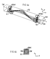
- Figure 4 shows an inventive US flow meter with spiral-shaped sonication of the flow channel.
- Figure 5 shows the dimensions of the flow channel for the determination the angle of reflection.
- Figure 6 shows a further embodiment of an inventive US flow meter.
- Figure 7 shows the error curve for the US flow meter Figure 4.
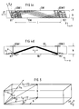
- Figure 8 shows a reflector of the US flow meter of Figure 4th
- Figure 9 shows the error curve for the US flow meter Figure 6.
- Figure 10 shows a reflector of the US flow meter of Figure 6.
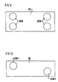
- FIG. 11 and 12 show further exemplary embodiments according to the invention US flow meter with several US transmit and receive transducers or with axially offset US transceivers.
- the reflection angle be calculated.
- ⁇ for the ceiling and ground reflection, which in the embodiment shown gives the classic V-way of sound propagation, comes a new angle ⁇ for reflection on the side walls added (see Fig. 4c).
- the V-shaped sound path is characterized in that the Sound from converter USW1 via reflector R1 to the flow channel ceiling SD arrives, reflected from there towards R2 and is diverted from R2 to the ultrasonic transducer USW2 (a ceiling reflection, see. Fig. 4d).
- the Ultrasound emitted by a transmitter transducer over the stations -first reflector-flow channel ceiling-flow channel floor-flow channel ceiling-second Reflector to receive converter (three reflections on the walls of the flow channel).
- ⁇ v 0.5l arctane (
- ) 0.5l arctane (l ⁇ v /H)
- ⁇ w 0.5 l arctane (
- ) 0.5 l arctane (l ⁇ w /H)
- Both reflectors R1 and R2 and thus also the reflection surfaces RF1 and RF2 are rotated by the azimuth angle ⁇ (see FIG. 4c).
- the direction of rotation is irrelevant because symmetrical configurations arise.
- One reflector is rotated by the azimuth angle ⁇ , the other by the azimuth angle - ⁇ .
- the reflectors are each divided into two reflecting surfaces. Each of these reflection surfaces has its own alignment + ⁇ or - ⁇ , (see Figure 6c).
- the reflection surface RF11 of the first R1 is rotated by the angle - ⁇
- the reflection surface RF12 of the reflector R1 is rotated by the angle + ⁇ .
- the reflection surfaces RF21 and RF22 of the second reflector R2 are rotated in the same way.
- the determination of the azimuth angle ⁇ results, as in the case of exemplary embodiments 1 and 2, from the above equation.
- Such a combination of the reflectors splits the incident wavefront into two wavefronts which continue in different directions and which recombine in the second reflector R2 after having traveled through an equally long path.
- the azimuth angle ⁇ is chosen so that the first reflector R1 and the second reflector R2 result in a convex combination, ie the first reflection surface RF11 of the first reflector R1 is around the azimuth angle - ⁇ , the second reflection surface RF21 of the first reflector R1 is around the azimuth angle + ⁇ , the first reflection surface RF12 of the second reflector R2 is rotated by the azimuth angle + ⁇ and the second reflection surface RF22 of the second reflector R2 is rotated by the azimuth angle - ⁇ .
- the recombination of the wavefront in the second reflector R2 takes place here with redistribution of the sensitivity from the center to the edge and vice versa. Although this improves the distribution, signal level losses can be expected.
- the azimuth angle ⁇ is chosen such that the first reflector R1 and the second reflector R2 result in a concave combination, ie the first reflection surface RF11 of the first reflector R1 is by the azimuth angle + ⁇ , the second reflection surface RF21 of the first reflector R1 is by the Azimuth angle - ⁇ , the first reflection surface RF12 of the second reflector R2 is rotated by the azimuth angle + ⁇ and the second reflection surface RF22 of the second reflector R2 by the azimuth angle - ⁇ .
- the wave front is recombined here as in the fourth embodiment.
- the distance l ⁇ do not fall below the specified value range, otherwise the signal quality due to the high number of reflections would suffer.
- the embodiment 1 shown in Figure 4 with a V-shaped Sound path showed the best results in tests the linearity and the material independence of the characteristic (cf. see Figure 7).
- the error with the test medium glycol was in the tested measuring range from 100 - 4000 l / h at less than ⁇ 1.5 %.
- the measurement error was included with the sonication parallel to the side wall small rivers at> 18%. For water, the mistakes are in one Band of ⁇ 0.8% (previously 9%), each in comparison with one MID flow meter for which a maximum error of 0.5% can be accepted.
- the reflector shown in FIG. 8 can be used in particular in a flow meter according to FIG. 4.
- the reflector is preferably made of brass and has the dimensions given in the following table. This table also contains the dimensions of the flow channel.
- Sidewall angle of attack ⁇ 90
- the reflectors used in the flow meter according to FIG. 6 can be produced from the components shown in FIG. 10 as follows: From each pair of part B, the gray marked parts and once the white parts are cut as indicated in C and D. A part E and F are composed of one half each from C and D (two gray parts make up part E and two white parts make up part F). The dimensions and angles are given in Fig. 10 and Table 2.
- the measuring device is not only for Flow measurement suitable for various liquids, but also for the flow measurement of various gases and also for water flow meters, referred to as heat meters in heating-cooling systems.
Abstract
Description
Die Erfindung betrifft einen US-Durchflußmesser nach dem Oberbegriff
des Patentanspruchs 1.The invention relates to a US flow meter according to the preamble
of
Bei der Durchflußmessung von bewegten flüssigen oder gasförmigen Medien (Fluiden) mit Ultraschall besteht das Problem, daß das vom Empfänger (Ultraschallwandler) gelieferte Meßsignal nicht nur vom Durchfluß, sondern auch vom jeweiligen Strömungsprofil im Meßrohr und der Art des durchströmenden Fluids abhängt. Je nach Strömungsgeschwindigkeit ergeben sich verschiedene Strömungsprofile. Das in Figur 1a gezeigte laminare Strömungsprofil in einem Rohr mit viereckigem Querschnitt tritt bei langsamer Strömungsgeschwindigkeit auf.Die im Inneren des Rohres eingezeichneten Linien veranschaulichen Bereiche gleicher Strömungsgeschwindigkeit. Laminare Strömungsprofile können durch eine parabolische Form, vgl. Figur1c, beschrieben werden. Die höchsten Strömungsgeschwindigkeiten treten in der Rohrmitte auf. Je größer der Durchfluß, also je hoher die Strömungsgeschwindigkeit ist, desto mehr nähert sich das Strömungsprofil einer Kastenform an. Figur 1b zeigt ein turbulentes Strömungsprofil, das bei hohen Strömungsgeschwindigkeiten auftritt. In weiten Bereichen des Rohres bleibt die Strömungsgeschwindigkeit in etwa gleich.When measuring the flow of moving liquid or gaseous Media (fluids) with ultrasound there is the problem that the measurement signal supplied by the receiver (ultrasonic transducer) not only from the flow, but also from the respective flow profile in the measuring tube and the type of fluid flowing through. Depending on the flow velocity, there are different ones Flow profiles. The laminar flow profile shown in Figure 1a in a tube with a square cross-section occurs slow flow rate on the inside of the pipe drawn lines illustrate areas of the same Flow velocity. Laminar flow profiles can through a parabolic shape, cf. Figure 1c be described. The highest flow rates occur in the middle of the pipe on. The greater the flow, the higher the flow rate is, the closer the flow profile approaches a box shape. FIG. 1b shows a turbulent flow profile, that occurs at high flow rates. In The flow velocity remains in large areas of the pipe about the same.
Die bisher bekannten Ultraschallwandler haben eine annähernd
gaußförmige Empfindlichkeitsverteilung. Die maximale Empfindlichkeit
des Ultraschallwandlers liegt in dessen Zentrum. Zum
Rand hin nimmt sie stark ab. Zusätzlich wird die Empfindlichkeit
durch die Rohrwandeigenschaften stark beeinflußt, wenn
durch die Rohrwand eingestrahlt wird.
Beschallt man nun mit einem Ultraschallwandler in einem Strömungskanal
das bewegte Medium, wie dies aus der DE 40 10 148 A1
bekannt ist, um aus der Schallaufzeit oder mittels des Dopplereffekts
die Strömungsgeschwindigkeit zu bestimmen, so wird,
insbesondere bei laminarem Strömungsprofiffi, die in der Strömungskanalmitte
auftretende höchste Strömungsgeschwindigkeit
stärker bewertet als die am Rand des Strömungskanals auftretende
niedrigere Strömungsgeschwindigkeit. Dies hat zur Folge,
daß sich für jedes Strömungsprofil und für jedes Fluid eine eigene
Meßkennlinie ergibt, was zu einer aufwendigen Auswerteeinheit
führt.The previously known ultrasonic transducers have an almost Gaussian sensitivity distribution. The maximum sensitivity of the ultrasound transducer lies in its center. It decreases sharply towards the edge. In addition, the sensitivity is strongly influenced by the properties of the pipe wall when irradiation is carried out through the pipe wall.
If you now sonicate the moving medium with an ultrasound transducer in a flow channel, as is known from DE 40 10 148 A1, in order to determine the flow velocity from the sound propagation time or by means of the Doppler effect, especially in the case of laminar flow profiles, the flow in the middle of the flow channel the highest flow velocity occurring is rated more strongly than the lower flow velocity occurring at the edge of the flow channel. The result of this is that there is a separate measurement characteristic for each flow profile and for each fluid, which leads to a complex evaluation unit.
Weiterhin ist bei dem in der DE 40 10 148 A1 beschriebenen Durchflußmesser von Nachteil, daß das Ultraschallsignal sich aufgrund des Meßrohraufbaus nicht nur w-förmig, sondern auch auf einem parasitären v-förmigen Weg ausbreiten kann und deshalb zusätzliche Maßnahmen zur Unterdrückung der daraus resultierenden Signalanteile erforderlich sind.Furthermore, that described in DE 40 10 148 A1 Flow meter disadvantageous that the ultrasonic signal itself due to the measuring tube structure not only w-shaped, but also can spread on a parasitic v-shaped path and therefore additional measures to suppress the resulting Signal components are required.
Aus H. Bernard "Ultraschall-Durchflußmessung", messen + prüfen/automatik, Heft 5, 1983, Seite 258 bis 263 ist ein Durchflußmesser mit einem von einem flüssigen Medium durchströmten Meßrohr bekannt, bei dem Störungen des Strömungsprofils reduziert werden, indem von mehreren Ultraschallwandlern erzeugte Meßstrahlen über den Rohrquerschnitt verteilt werden. Der Aufwand zur Signalauswertung steigt mit der Anzahl der verwendeten Ultraschallwandler.From H. Bernard "Ultrasonic flow measurement", measure + examine / automatic, issue 5, 1983, pages 258 to 263 is a Flow meter with one of a liquid medium flow through the measuring tube is known, in which disturbances of the Flow profile can be reduced by several Ultrasonic transducers generated measuring beams over the Pipe cross section can be distributed. The effort for signal evaluation increases with the number of ultrasonic transducers used.
L. C. Linworth beschreibt in "Ultrasonic Measurements for Process Control" Academic Press, San Diego, 1989, auf den Seiten 288 ff Durchflußmesser, deren Meßrohr mit einem Ultraschallsendewandler und einem Ultraschallempfangswandler versehen ist. Die Abstrahl- und Empfangsflächen der Ultraschallwandler sind derart abgeschrägt, daß der abgestrahlte Schall je nach Ausführungsform an einer, zwei oder vier Reflexionsstellen im Meßrohr reflektiert wird.L. C. Linworth describes in "Ultrasonic Measurements for Process Control "Academic Press, San Diego, 1989 Pages 288 ff flow meter, the measuring tube with a Ultrasound transmission transducer and an ultrasound reception transducer is provided. The radiation and reception areas of the Ultrasonic transducers are chamfered in such a way that the emitted one Sound depending on the embodiment on one, two or four reflection points in the measuring tube is reflected.
Aus dem Dokument US 4 103 551 ist ein Ultraschallmeßsystem für verschiedene Durchflußeigenschaften angegeben. Die Vorrichtung dient zur Ultraschalldurchflußmessung in einem runden Rohr, das zwei Ultraschallwandler aufweist, die entlang eines akustischen Wegs in dem Rohr miteinander kommunizieren. Der akustische Weg beinhaltet eine Sehne, die den Rohrradius halbiert.An ultrasonic measuring system is known from document US 4 103 551 specified for different flow properties. The device is used for ultrasonic flow measurement in a round Pipe that has two ultrasonic transducers running along it communicate with each other along an acoustic path in the pipe. The acoustic path includes a chord that represents the pipe radius halved.
Aus dem Stand der Technik EP 0 268 314 A1 ist eine Vorrichtung
zur Bestimmung des Durchflußes in einem zylindrischen
Rohr bekannt. Die Durchflußmeßvorrichtung weist ein erstes
und ein zweites Paar Ultraschallwandler auf, wobei jeweils
einer der Ultraschallwandler ein Ultraschallsignal schräg in
das Rohr abstrahlt, in welchem das Signal an zwei Stellen des
Meßrohrs reflektiert wird und schräg zum entsprechenden Empfangswandler
gelangt. Durch diese Vorrichtung können Störungen
durch im Fluß auftretende Wirbel kompensiert werden.A device is known from the
Der Erfindung liegt die Aufgabe zugrunde, eine Vorrichtung zu schaffen, die eine höhere Meßgenauigkeit hat und deren Meßsignal nurmehr vom Durchfluß und nicht mehr von der Art des verwendeten Fluids und dem vorliegenden Strömungsprofil abhängt.The invention has for its object a device create that has a higher measurement accuracy and their measurement signal only from the flow and no longer from the type of used fluids and the current flow profile depends.
Die Aufgabe wird erfindungsgemäß durch eine Vorrichtung gemäß
dem Patentanspruch 1 gelöst.The object is achieved according to the invention by a device
solved the
Vorteilhafte Weiterbildungen der Erfindung ergeben sich aus den abhängigen Ansprüchen.Advantageous developments of the invention result from the dependent claims.
Anhand der Figuren soll die Erfindung näher erläutert werden. The invention will be explained in more detail with reference to the figures.
Figur 1 zeigt ein laminares und ein turbulentes Strömungsprofil im Strömungskanalquerschnitt und mögliche Strömungsprofile im Strömungskanal in der Seitenansicht.Figure 1 shows a laminar and a turbulent flow profile in the flow channel cross section and possible flow profiles in the flow channel in side view.
Figur 2 zeigt einen konventionellen US-Durchflußmesser mit seitenwandparalleler Durchschallung des Strömungskanals.Figure 2 shows a conventional US flow meter with sonication of the flow channel parallel to the side wall.
Figur 3 zeigt die Fehlerkurve des US-Durchflußmessers nach Figur 2.FIG. 3 shows the error curve of the US flow meter Figure 2.
Figur 4 zeigt einen erfindungsgemäßen US-Durchflußmesser mit spiralförmiger Durchschallung des Strömungskanals.Figure 4 shows an inventive US flow meter with spiral-shaped sonication of the flow channel.
Figur 5 zeigt die Bemaßung des Strömungskanals für die Bestimmung der Reflexionswinkel.Figure 5 shows the dimensions of the flow channel for the determination the angle of reflection.
Figur 6 zeigt ein weiteres Ausführungsbeispiel eines erfindungsgemäßen US-Durchflußmessers. Figure 6 shows a further embodiment of an inventive US flow meter.
Figur 7 zeigt die Fehlerkurve für den US-Durchflußmesser nach Figur 4.Figure 7 shows the error curve for the US flow meter Figure 4.
Figur 8 zeigt einen Reflektor des US-Durchflußmessers nach Figur 4.Figure 8 shows a reflector of the US flow meter of Figure 4th
Figur 9 zeigt die Fehlerkurve für den US-Durchflußmesser nach Figur 6.Figure 9 shows the error curve for the US flow meter Figure 6.
Figur 10 zeigt einen Reflektor des US-Durchflußmessers nach Figur 6.Figure 10 shows a reflector of the US flow meter of Figure 6.
Fig. 11 und 12 zeigen weitere Ausführungsbeispiele erfindungsgemäßer US-Durchflußmesser mit mehreren US-Sende- und Empfangswandlern bzw. mit axial versetzten US-Sende-Empfangswandlern.11 and 12 show further exemplary embodiments according to the invention US flow meter with several US transmit and receive transducers or with axially offset US transceivers.
In Meßanordnungen für Strömungskanäle mit Durchmessern d ≤ 50 mm wird der Schall üblicherweise parallel zu den Strömungskanal Seitenwänden SW von einem als Sender dienenden US-Wandler USW1 zu einem US-Empfangswandler USW2 geführt (s. Fig. 2). Bei dem dargestellten Durchflußmesser läuft der Schall auf einem V-förmigen Weg durch den Strömungskanal, wobei der dem Sender USW1 gegenüberliegende Reflektor R1 den Ultraschall in Richtung Strömungskanalecke SD und der zweite Reflektor R2 den Ultraschall in Richtung des Empfangswandlers USW2 umlenkt. Die Richtcharakteristik der verwendeten US-Wandler bewirkt eine erhöhte Sensitivität auf den Verbindungslinien zwischen den Wandlerzentren. Hierbei kann man eine gaußförmige Verteilung der Sensitivität vom Wandlerzentrum zum Rand hin annehmen. Diese ist in Fig. 2 für einen linienförmigen Ausschnitt aus dem Wandler USW1 durch eine grau-Codierung veranschaulicht (schwarz: = höchste, hellgrau: = geringste Sensitivität). Wenn sich der Ultraschall nur parallel zu den Seitenwänden SW ausbreitet, laufen die Strahlen (die Ausbreitungsrichtung einer Wellenfront wird im folgenden vereinfachend mit der Ausbreitungsrichtung von Strahlen veranschaulicht) mit der höchsten Sensitivität durch den mittleren Bereich des Strömungskanals und registrieren folglich auch die höheren Geschwindigkeiten mit einer höheren Wertigkeit. Demgegenüber werden die Randbereiche des Strömungskanals von den weniger sensitiven Strahlen durchlaufen, so daß man die dort auftretenden niedrigen Geschwindigkeiten mit einer entsprechend geringeren Wertigkeit registriert. Daraus resultieren Fehlerkurven mit einem sehr großen Fehler bei kleinen Geschwindigkeiten (= kleiner Durchfluß), der für höhere Geschwindigkeiten (= großer Durchfluß) langsam abnimmt. In der in Fig. 3 gezeigten Fehlerkurve sind die relativen Meßfehler der US-Messung im Vergleich zu einer Referenzmethode, z. B. der Messung mit einem magnetisch-induktiven Durchflußmesser (MID) dargestellt.In measuring arrangements for flow channels with diameters d ≤ 50 mm the sound is usually parallel to the flow channel Side walls SW of a US converter USW1 serving as a transmitter led to a US receive converter USW2 (see FIG. 2). In which Flow meter shown, the sound runs on a V-shaped Path through the flow channel, the USW1 opposite reflector R1 the ultrasound in the direction Flow channel corner SD and the second reflector R2 the ultrasound deflected in the direction of the receive converter USW2. The Directional characteristics of the US converters used result in an increased Sensitivity on the connecting lines between the Converter centers. Here you can see a Gaussian distribution of sensitivity from the converter center to the edge. This is in Fig. 2 for a linear section from the Converter USW1 illustrated by a gray coding (black: = highest, light gray: = lowest sensitivity). If the ultrasound only spreads parallel to the side walls SW, run the rays (the direction of propagation of a The wavefront is simplified in the following with the direction of propagation illustrated by rays) with the highest Sensitivity through the middle area of the flow channel and consequently also register the higher speeds with a higher value. In contrast, the edge areas of the flow channel from the less sensitive rays go through, so that you can see the low speeds occurring there with a correspondingly lower value registered. This results in error curves with a very large errors at low speeds (= small flow), for higher speeds (= large flow) slowly decreases. 3 are in the error curve the relative measurement errors of the US measurement compared to a Reference method, e.g. B. the measurement with a magnetic-inductive Flow meter (MID) shown.
Um eine weitgehend homogene Durchschallung, d. h. eine gleichmäßige Sensitivität über den Kanalquerschnitt zu gewährleisten, werden Schallwellen hoher Sensitivität, also die vom Zentrum des Wandlers USW1 ausgehenden Ultraschallwellen, mit Hilfe geeignet orientierter Reflektoren R1/R2 durch alle Bereiche des Strömungskanals geführt (s. Fig. 4 und 6). Dies geschieht durch die kombinierte und abwechselnde Nutzung der Reflexion der Schallwellen an den Seitenwänden SW, der Decke SD und dem Boden SB des Strömungskanals. Anstatt den Ultraschall ausschließlich parallel zu den Seitenwänden SW von einem ersten zu einem zweiten Ultraschallwandler zu senden, also lediglich die Decken- und Bodenreflexion zu nutzen, durchläuft der Ultraschall den Strömungskanal in dem erfindungsgemäßen Durchflußmesser spiralförmig. Die damit erreichte Homogenisierung der Durchschallung des Strömungskanals mit Strahlen unterschiedlichster Sensitivität wird besonders durch Vergleich der Figuren 4b und 6b mit Fig. 2b deutlich. In order to achieve a largely homogeneous transmission, H. an even one To ensure sensitivity across the channel cross-section, become sound waves of high sensitivity, i.e. those from the center of the transducer USW1 outgoing ultrasonic waves, with the help of suitable oriented reflectors R1 / R2 through all areas of the Flow channel guided (see. Fig. 4 and 6). This happens through the combined and alternating use of the reflection of the Sound waves on the side walls SW, the ceiling SD and the floor SB of the flow channel. Instead of the ultrasound exclusively parallel to the side walls SW from a first to a second To send ultrasonic transducers, i.e. only the ceiling and using ground reflection, the ultrasound passes through the Flow channel in the flow meter according to the invention spiral. The homogenization of the sonication achieved with this of the flow channel with rays of different sensitivity is particularly by comparing Figures 4b and 6b with Fig. 2b clearly.
Die im folgenden beschriebenen Ausführungsbeispiele beziehen sich auf einen Strömungskanal der Länge l (l: = Abstand der Wandlerzentren) mit quadratischem Querschnitt (Breite b, Hohe h).The exemplary embodiments described below relate flow channel of length l (l: = distance of the Converter centers) with a square cross-section (width b, height H).
Zur Festlegung der Geometrie des Strömungskanals und der Orientierung der Reflektoren R1 und R2, müssen die Reflexionswinkel berechnet werden. Zu dem konventionellen Winkel α für die Dekken- und Boden-Reflexion, welcher in dem gezeigten Ausführungsbeispiel den klassischen V-Weg der Schallausbreitung ergibt, kommt ein neuer Winkel Ψ für die Reflexion an den Seitenwänden hinzu (s. Fig. 4c).To determine the geometry of the flow channel and the orientation of reflectors R1 and R2, the reflection angle be calculated. To the conventional angle α for the ceiling and ground reflection, which in the embodiment shown gives the classic V-way of sound propagation, comes a new angle Ψ for reflection on the side walls added (see Fig. 4c).
Erfindungsgemäß werden die beiden Winkel α und Ψ unter Berücksichtigung
der folgenden Randbedingungen berechnet und kombiniert:
Der V-förmige Schallweg ist dadurch gekennzeichnet, daß der Schall vom Wandler USW1 über den Reflektor R1 zur Strömungskanaldecke SD gelangt, von dort in Richtung R2 reflektiert und von R2 zum Ultraschallwandler USW2 umgelenkt wird (eine Deckenreflexion, vgl. Fig. 4d).The V-shaped sound path is characterized in that the Sound from converter USW1 via reflector R1 to the flow channel ceiling SD arrives, reflected from there towards R2 and is diverted from R2 to the ultrasonic transducer USW2 (a ceiling reflection, see. Fig. 4d).
Bei dem nicht dargestellten W-förmigen Schallweg gelangt der von einem Sendewandler ausgestrahlte Ultraschall über die Stationen -erster Reflektor-Strömungskanaldecke-Strömungskanalboden-Strömungskanaldecke-zweiter Reflektor- zum Empfangswandler (drei Reflexionen an den Wandungen des Strömungskanals).In the W-shaped sound path, not shown, the Ultrasound emitted by a transmitter transducer over the stations -first reflector-flow channel ceiling-flow channel floor-flow channel ceiling-second Reflector to receive converter (three reflections on the walls of the flow channel).
Ohne Querschall (Ψ = 0) berechnen sich die Elevationswinkel
αV für den V-förmigen Schallweg und αW für den W-förmigen
Schallweg zu:
Mit Querschall (Azimutwinkel ψ ≠ 0) ergeben sich die beiden
Elevationswinkel αv und αw zu:
Für den Azimutwinkel ψ (Querschall: Reflexion an den Seitenwänden
SW) sind durch Reflektorsegmentierung und Orientierung eine
Fülle von Werten möglich. Jedoch sind nur wenige geeignet die
homogene Verteilung der Sensitivität zu gewährleisten. Aus dem
Abstand lψ des ersten Reflektors R1 zum Reflexionspunkt an der
Seitenwand SW und der Strömungskanalbreite b läßt sich der
Azimutwinkel ψ zu:
Beide Reflektoren R1 und R2 und damit auch die Reflexionsflächen
RF1 und RF2 werden um den Azimutwinkel ψ gedreht (s. Fig.
4c). Die Drehrichtung ist unerheblich, weil symmetrische Konfigurationen
entstehen. Der Abstand lψ kann aus folgender Menge
gewählt werden:
Höhere Ordnungen werden hier vernachlässigt, da ansonsten die Signalqualität wegen der großen Anzahl von Reflexionen leiden würde.Higher orders are neglected here, otherwise the Signal quality suffer because of the large number of reflections would.
Ein Reflektor wird um den Azimutwinkel ψ, der andere um den
Azimutwinkel -ψ gedreht. Der Abstand lψ kann dann zu:
Die Reflektoren werden in jeweils zwei Reflexionsflächen unterteilt.
Jede dieser Reflexionsflächen erhält eine eigene Ausrichtung
+ψ bzw. -ψ, (siehe Figur 6c). Die Reflexionsfläche
RF11 des ersten R1 ist um den Winkel -ψ, die Reflexionsfläche
RF12 des Reflektors R1 ist um den Winkel +ψ gedreht. Die Reflexionsflächen
RF21 und RF22 des zweiten Reflektors R2 sind auf
dieselbe Art und Weise gedreht. Die Bestimmung des Azimutwinkels
ψ ergibt sich, wie bei den Ausführungsbeispielen 1 und 2,
aus obiger Gleichung. Durch eine derartige Kombination der
Reflektoren wird die einfallende Wellenfront in zwei in unterschiedlicher
Richtung weiterlaufende Wellenfronten aufgespalten,
die sich nach Durchlaufen eines gleichlangen Weges im
zweiten Reflektor R2 rekombinieren. Der Abstand lψ kann aus der
Menge
Der Azimutwinkel ψ wird so gewählt, daß der erste Reflektor R1
und der zweite Reflektor R2 eine konvexe Kombination ergeben,
d.h. die erste Reflexionsfläche RF11 des ersten Reflektors R1
ist um den Azimutwinkel -ψ, die zweite Reflexionsfläche RF21
des ersten Reflektors R1 ist um den Azimutwinkel +ψ, die erste
Reflexionsfläche RF12 des zweiten Reflektors R2 ist um den
Azimutwinkel +ψ und die zweite Reflexionsfläche RF22 des zweiten
Reflektors R2 ist um den Azimutwinkel -ψ gedreht. Die Rekombination
der Wellenfront im zweiten Reflektor R2 geschieht
hier mit Umverteilung der Sensitivität vom Zentrum zum Rand hin
und umgekehrt. Hierdurch wird die Verteilung zwar verbessert,
es sind jedoch Signalpegelverluste zu erwarten. Der Abstand lψ
sollte zu
Es wird der Azimutwinkel Ψ so gewählt, daß der erste Reflektor
R1 und der zweite Reflektor R2 eine konkave Kombination ergeben,
d.h. die erste Reflexionsfläche RF11 des ersten Reflektors
R1 wird um den Azimutwinkel +ψ, die zweite Reflexionsfläche
RF21 des ersten Reflektors R1 wird um den Azimutwinkel -ψ, die
erste Reflexionsfläche RF12 des zweiten Reflektors R2 wird um
den Azimutwinkel +ψ und die zweite Reflexionsfläche RF22 des
zweiten Reflektors R2 um den Azimutwinkel -ψ gedreht. Die
Rekombination der Wellenfront erfolgt hier wie im 4. Ausführungsbeispiel.
Der Abstand lψ ist vorteilhafterweise zu
Bei allen genannten Ausführungsbeispielen sollte der Abstand lψ den angegebenen Wertebereich nicht unterschreiten, da ansonsten die Signalqualität aufgrund der hohen Anzahl an Reflexionen leiden würde.In all the embodiments mentioned, the distance lψ do not fall below the specified value range, otherwise the signal quality due to the high number of reflections would suffer.
Das in Figur 4 gezeigte Ausführungsbeispiel 1 mit V-förmigem
Schallweg zeigte bei Versuchen die besten Resultate bezüglich
der Linearität und der Stoffunabhängigkeit der Kennlinie (vgl.
hierzu Figur 7). Der Fehler bei dem Testmedium Glykol lag im
getesteten Meßbereich von 100 - 4000 l/h bei weniger als ± 1,5
%. Bei dem in Figur 2 dargestellten Ultraschalldurchflußmesser
mit seitenwandparalleler Durchschallung lag der Meßfehler bei
kleinen Flüssen bei > 18%. Für Wasser liegen die Fehler in einem
Band von ≤ 0,8 % (vorher 9 %), jeweils im Vergleich mit einem
MID-Durchflußmesser, für den ein maximaler Fehler von 0,5 %
angenommen werden kann.The
Den in Fig. 8 dargestellten Reflektor kann man insbesondere in
einem Durchflußmesser gemäß Fig. 4 verwenden. Der Reflektor ist
vorzugsweise aus Messing gefertigt und besitzt die in der folgenden
Tabelle angegebene Bemaßung. Diese Tabelle enthält auch
die Abmessungen des Strömungskanals.
x=aa Cos[α]
bb=aa Sin[α]
X bezeichnet die horizontale Projektion der Schrägfläche aa und
bb die Höhe der Ränder.
x = aa cos [α]
bb = aa Sin [α]
X denotes the horizontal projection of the sloping surface aa and bb the height of the edges.
Bei dem in Figur 6 gezeigten Ausführungsbeispiel 3 ergaben sich ähnlich gute Resultate bezüglich der Linearität und der Stoffunabhängigkeit der Kennlinie (s. Fig. 9). Der Nutzsignalpegel liegt allerdings etwas niedriger als bei dem Ausführungsbeispiel 3. Der Fehler beim Testen mit Glykol (Wasser) lag im Meßbereich von 100 - 4000 l/h bei weniger als ± 2% (1%).In the exemplary embodiment 3 shown in FIG. 6, this resulted similarly good results in terms of linearity and substance independence the characteristic curve (see FIG. 9). The useful signal level is, however, somewhat lower than in the exemplary embodiment 3. The error when testing with glycol (water) was in Measuring range from 100 - 4000 l / h at less than ± 2% (1%).
Die im Durchflußmesser gemäß Fig. 6 verwendeten Reflektoren
lassen sich aus den in Fig. 10 dargestellten Bauteilen wie
folgt herstellen:
Aus je einem Paar des Teils B werden einmal die grau markierten
Teile und einmal die weißen Teile wie in C und D angegeben passend
geschnitten. Aus je einer Hälfte aus C und D werden ein
Teil E bzw. F zusammengesetzt (zwei graue Teile ergeben einen
Teil E und zwei weiße Teile ergeben ein Teil F). Die Bemaßung
und die Winkel sind in Fig. 10 und Tabelle 2 angegeben.
From each pair of part B, the gray marked parts and once the white parts are cut as indicated in C and D. A part E and F are composed of one half each from C and D (two gray parts make up part E and two white parts make up part F). The dimensions and angles are given in Fig. 10 and Table 2.
Im nachfolgenden sind weitere Variationsmöglichkeiten zum Aufbau der erfindungsgemäßen Meßvorrichtung angegeben:
- Alle Kombinationen der axialen und queraxialen Reflexionen
- Längenvariation
- Variation des Verhältnisses der Rohrabmessungen
- Kombination zweier oder mehrerer Meßrohre mit verschiedener Meßcharakteristik
- Verwendung von mehreren Sendern bei größeren Nennweiten
- sechseckiger Querschnitt
- ovaler oder runder Querschnitt
- Durchmesseränderung in axialer Richtung, konische Rohre
- Reflektoren auf verschiedenen Wänden
- gedrehte, ebene Reflektoren
- gedrehte und in mehrere Reflexionsflächen aufgeteilte Reflektoren
- gedrehte und/oder ungedrehte gekrümmte Reflektoren
- Sende- u. Empfangswandler auf einer Seite des Strömungskanals
- Sende- und Empfangswandler gegenüberliegend
- Sende- und Empfangswandler axial versetzt (s. Fig. 12)
- mehrere Sende- und Empfangswandler verteilt auf verschiedenen Seitenwänden (s. Fig. 11).
- All combinations of axial and transverse axial reflections
- Length variation
- Varying the ratio of the pipe dimensions
- Combination of two or more measuring tubes with different measuring characteristics
- Use of several transmitters with larger nominal sizes
- hexagonal cross section
- oval or round cross-section
- Diameter change in the axial direction, conical tubes
- Reflectors on different walls
- turned, flat reflectors
- rotated reflectors divided into several reflecting surfaces
- twisted and / or untwisted curved reflectors
- Send u. Receive converter on one side of the flow channel
- Transmitter and receiver converter opposite
- Transmitter and receiver transducer axially offset (see Fig. 12)
- several transmit and receive converters distributed on different side walls (see Fig. 11).
Die erfindungsgemäße Meßvorrichtung ist nicht nur für die Durchflußmessung verschiedenster Flüssigkeiten geeignet, sondern auch für die Durchflußmessung verschiedenster Gase und auch für die, als Wärmezähler bezeichneten, Wasser- Durchflußmesser in Heiz-Kühlsystemen.The measuring device according to the invention is not only for Flow measurement suitable for various liquids, but also for the flow measurement of various gases and also for water flow meters, referred to as heat meters in heating-cooling systems.
Claims (12)
- Flowmeter having a measurement tube through which a gaseous or liquid medium flows, having an ultrasound transducer (USW1) which ensonifies the medium, having a first reflector (R1) which is arranged in the measurement tube and having an ultrasound receiving transducer (USW2), the individual components being oriented with respect to one another in such a manner that the ultrasound is reflected at least once on a planar wall of the measurement tube, a normal to the surface of the first reflector (R1) having three components, which are not zero, in a rectangular coordinate system, one of whose axes is oriented parallel to the flow direction (F).
- Flowmeter according to Claim 1,
characterized by
a first reflector (R1) which is of segmented construction, the normals to the surfaces of the reflector segments (RF11, RF12) not being oriented parallel to one another. - Flowmeter according to Claim 1 or 2,
characterized
in that the first reflector (R1) is arranged opposite the ultrasound transducer (USW1) in the measurement tube. - Flowmeter according to one of Claims 1 to 3,
characterized
in that the ultrasound transducer (USW1) injects the ultrasound into the measurement tube at right angles to the flow direction. - Flowmeter according to one of Claims 1 to 4,
characterized by
a second reflector (R2) which is arranged in the measurement tube. - Flowmeter according to Claim 5,
characterized
in that a normal to the surface of the second reflector (R2) has three components in the rectangular coordinate system. - Flowmeter according to Claim 5 or 6,
characterized by
a second reflector (R2) which is of segmented construction, the normals to the surfaces of the reflector segments (RF21, RF22) not being oriented parallel to one another. - Flowmeter according to one of Claims 5 to 7,
characterized
in that the second reflector (R2) is arranged opposite the ultrasound receiving transducer (USW2) in the measurement tube. - Flowmeter according to one of Claims 1 to 8,
characterized by
a planar first and/or second reflector (R1, R2). - Flowmeter according to one of Claims 1 to 9,
characterized
in that the reflector segments (RF11, RF12, RF21, RF22) of the first and/or second reflector (R1, R2) are planar surfaces. - Flowmeter according to one of Claims 1 to 10,
characterized
in that one axis of symmetry of the ultrasound transducer (USW1) is oriented parallel to one axis of symmetry of the ultrasound receiving transducer (USW2). - Flowmeter according to one of Claims 1 to 10,
characterized
in that one axis of symmetry of the ultrasound transducer (USW1) is inclined with respect to one axis of symmetry of the ultrasound receiving transducer (USW2).
Applications Claiming Priority (3)
| Application Number | Priority Date | Filing Date | Title |
|---|---|---|---|
| DE4336370 | 1993-10-25 | ||
| DE4336370A DE4336370C1 (en) | 1993-10-25 | 1993-10-25 | Device for flow measurement |
| PCT/DE1994/001190 WO1995012110A1 (en) | 1993-10-25 | 1994-10-11 | Flow measurement device |
Publications (2)
| Publication Number | Publication Date |
|---|---|
| EP0725922A1 EP0725922A1 (en) | 1996-08-14 |
| EP0725922B1 true EP0725922B1 (en) | 1998-07-15 |
Family
ID=6500965
Family Applications (1)
| Application Number | Title | Priority Date | Filing Date |
|---|---|---|---|
| EP94928763A Expired - Lifetime EP0725922B1 (en) | 1993-10-25 | 1994-10-11 | Flow measurement device |
Country Status (9)
| Country | Link |
|---|---|
| US (1) | US5650572A (en) |
| EP (1) | EP0725922B1 (en) |
| JP (1) | JPH09504110A (en) |
| CN (1) | CN1079945C (en) |
| AT (1) | ATE168466T1 (en) |
| DE (2) | DE4336370C1 (en) |
| DK (1) | DK0725922T3 (en) |
| ES (1) | ES2119227T3 (en) |
| WO (1) | WO1995012110A1 (en) |
Families Citing this family (59)
| Publication number | Priority date | Publication date | Assignee | Title |
|---|---|---|---|---|
| DE4437588A1 (en) * | 1994-10-20 | 1996-04-25 | Siemens Ag | Ultrasonic flow meter |
| EP0715155B1 (en) * | 1994-12-02 | 2001-04-11 | Siemens Aktiengesellschaft | Ultrasonic flowmeter |
| US5969263A (en) * | 1995-04-08 | 1999-10-19 | Schlumberger Industries, S.A. | Ultrasonic fluid counter for attenuating parasitic ultrasonic waves |
| DE19542232A1 (en) | 1995-11-13 | 1997-05-15 | Siemens Ag | Ultrasonic flow meter for liquid or gaseous media |
| FR2748816B1 (en) * | 1996-05-17 | 1998-07-31 | Schlumberger Ind Sa | ULTRASONIC DEVICE FOR MEASURING THE FLOW SPEED OF A FLUID |
| DE19727960C2 (en) * | 1997-07-01 | 1999-10-14 | Peus Systems Gmbh | Device for the temporally high-resolution measurement of a gaseous volume flow, in particular an exhaust gas volume flow of an internal combustion engine, in a pipe through which it flows |
| DE19729473A1 (en) * | 1997-07-10 | 1999-02-04 | Meinecke Ag H | Ultrasonic flow meter |
| DE19743340C3 (en) * | 1997-09-30 | 2003-09-25 | Siemens Ag | flowmeter |
| DE29719677U1 (en) * | 1997-11-05 | 1998-12-10 | Siemens Ag | Flow meter |
| DE29719730U1 (en) * | 1997-11-06 | 1998-12-03 | Siemens Ag | Flow meter |
| DE19755152C1 (en) * | 1997-12-11 | 1999-05-06 | Siemens Ag | Ultrasonic flow gauge |
| DE19808642C1 (en) * | 1998-02-28 | 1999-08-26 | Flexim Flexible Industriemeste | Flow measuring device using ultrasound signals |
| DE19808701C2 (en) * | 1998-03-02 | 2000-01-20 | Georg F Wagner | Flow measuring device |
| DE19861186B4 (en) * | 1998-03-02 | 2005-09-08 | Schubert & Salzer Control Systems Gmbh | System for through flow measurement |
| DE29803911U1 (en) * | 1998-03-05 | 1999-04-01 | Siemens Ag | Flow meter |
| DE29803912U1 (en) * | 1998-03-05 | 1999-04-08 | Siemens Ag | Flow meter |
| US6098466A (en) * | 1998-06-09 | 2000-08-08 | Transonic Systems, Inc. | Ultrasonic flow sensor incorporating full flow illumination |
| IT1311771B1 (en) | 1999-02-24 | 2002-03-19 | Giorgio Bergamini | PERFECTED GAS FLOW METER WITH ULTRASOUNDS BASED ON PARABOLIC MIRRORS. |
| DE10034474C1 (en) * | 2000-07-15 | 2001-10-11 | Flexim Flexible Industriemeste | Liquid or gas characteristics measuring method using ultrasound has conical wavefront directed through pipe with detection of waves after propagation through the liquid or gas |
| JP2004520581A (en) * | 2001-01-09 | 2004-07-08 | ランディス+ギュル・ゲゼルシャフト・ミット・ベシュレンクテル・ハフツング | Flowmeter |
| US6901812B2 (en) * | 2002-12-30 | 2005-06-07 | Pti Technologies, Inc. | Single-body dual-chip Orthogonal sensing transit-time flow device |
| US20040129088A1 (en) * | 2002-12-30 | 2004-07-08 | D.C. Tigwell & Associates | Single-body dual-chip orthogonal sensing transit-time flow device using a parabolic reflecting surface |
| US6854339B2 (en) * | 2002-12-30 | 2005-02-15 | Pti Technologies, Inc. | Single-body dual-chip orthogonal sensing transit-time flow device using a parabolic reflecting surface |
| WO2004074783A1 (en) | 2003-02-24 | 2004-09-02 | Matsushita Electric Industrial Co., Ltd. | Ultrasonic type fluid measuring device |
| JP4186645B2 (en) * | 2003-02-24 | 2008-11-26 | 松下電器産業株式会社 | Ultrasonic flow measuring device |
| RU2264602C1 (en) * | 2004-04-12 | 2005-11-20 | Деревягин Александр Михайлович | Ultrasound method for measuring flow of liquid and/or gaseous substances and device for realization of said method |
| DE102004053673A1 (en) * | 2004-11-03 | 2006-05-04 | Endress + Hauser Flowtec Ag | Device for determining and / or monitoring the volume and / or mass flow rate of a medium |
| DE102005063314B4 (en) * | 2005-02-17 | 2010-07-08 | Hydrometer Gmbh | Flowmeter |
| US7152490B1 (en) | 2005-08-15 | 2006-12-26 | Daniel Measurement And Control, Inc. | Methods for determining transducer delay time and transducer separation in ultrasonic flow meters |
| DE102005040238A1 (en) * | 2005-08-24 | 2007-03-01 | Endress + Hauser Flowtec Ag | Device for determining and / or monitoring a process variable |
| DE202006021163U1 (en) | 2006-07-03 | 2013-08-01 | Endress + Hauser Flowtec Ag | Device for determining the concentrations of components of a gas mixture |
| DE102006030964A1 (en) | 2006-07-03 | 2008-01-10 | Endress + Hauser Flowtec Ag | Apparatus and method for determining the concentrations of components of a gas mixture |
| US8348879B2 (en) * | 2006-08-28 | 2013-01-08 | Novartis Ag | Surgical system having a cassette with an acoustic air reflector |
| DE102007004936B4 (en) * | 2006-12-19 | 2011-01-13 | Krohne Ag | ultrasonic flowmeter |
| DE102008029772A1 (en) * | 2008-06-25 | 2009-12-31 | Endress + Hauser Flowtec Ag | Method and measuring system for determining and / or monitoring the flow of a measuring medium through a measuring tube |
| EP2145696A1 (en) | 2008-07-15 | 2010-01-20 | UAB Minatech | Capacitive micromachined ultrasonic transducer and its fabrication method |
| EP2154491A1 (en) | 2008-08-07 | 2010-02-17 | UAB Minatech | Ultrasonic flow meter, transducer assembly and method |
| US7845240B1 (en) * | 2009-07-24 | 2010-12-07 | Elster NV/SA | Device and method for determining a flow characteristic of a fluid in a conduit |
| DE102009045620A1 (en) | 2009-10-13 | 2011-05-19 | Robert Bosch Gmbh | Ultrasonic flow sensor for detecting a flow of a fluid medium |
| US8181536B2 (en) * | 2009-12-19 | 2012-05-22 | Cameron International Corporation | Ultrasonic Flow Meter including a transducer having conical face |
| CN101907472A (en) * | 2010-07-05 | 2010-12-08 | 李俊国 | Ultrasonic flow measuring device |
| DE102011075997A1 (en) | 2011-05-17 | 2012-11-22 | Endress + Hauser Flowtec Ag | Ultrasonic flowmeter |
| DE102011076000A1 (en) | 2011-05-17 | 2012-11-22 | Endress + Hauser Flowtec Ag | Ultrasonic flowmeter |
| DE102011079250A1 (en) | 2011-07-15 | 2013-01-17 | Endress + Hauser Flowtec Ag | Ultrasonic flowmeter |
| CN102322980B (en) * | 2011-09-02 | 2013-05-22 | 山东二十度节能技术服务有限公司 | Ultrasonic heat meter body and method for determining position parameters of three-dimensional reflection surfaces of ultrasonic heat meter body |
| DE102012205640B4 (en) * | 2012-01-05 | 2018-05-30 | Continental Automotive Gmbh | level sensor |
| DE102012101098A1 (en) * | 2012-02-10 | 2013-08-14 | Endress + Hauser Flowtec Ag | Ultrasonic flowmeter and method for determining the flow rate or volumetric flow of a fluid |
| DE102012013916A1 (en) | 2012-07-16 | 2014-01-16 | Endress + Hauser Flowtec Ag | Ultrasonic flowmeter |
| DE102012109234A1 (en) | 2012-09-28 | 2014-04-03 | Endress + Hauser Flowtec Ag | Volumetric flow meter for determining flow rate and/or composition of e.g. gas of e.g. oil refinery, has devices that determine flow rate of mediums based on transit time difference method and thermal mass flow measurement |
| DE102012109237A1 (en) | 2012-09-28 | 2014-04-03 | Endress + Hauser Flowtec Ag | Flow meter, and use of this flow meter and method for determining the flow rate |
| DE102013105407A1 (en) | 2013-05-27 | 2014-11-27 | Endress + Hauser Flowtec Ag | Device for determining and / or monitoring the volume and / or mass flow of a medium |
| DE102013105922A1 (en) * | 2013-06-07 | 2014-12-11 | Endress + Hauser Flowtec Ag | Ultrasonic flowmeter |
| US10048108B2 (en) * | 2013-07-26 | 2018-08-14 | Zhejiang Joy Electronic Technology Co., Ltd. | Ultrasonic flow meter having an entrance of a sound channel equipped with a chamfer for a smooth and restraint turbulent flow |
| DE102014001165A1 (en) | 2013-12-19 | 2015-06-25 | Endress + Hauser Flowtec Ag | Apparatus and method for determining the concentrations of components of a gas mixture |
| US9304024B2 (en) * | 2014-01-13 | 2016-04-05 | Cameron International Corporation | Acoustic flow measurement device including a plurality of chordal planes each having a plurality of axial velocity measurements using transducer pairs |
| GB201411701D0 (en) * | 2014-07-01 | 2014-08-13 | Pcme Ltd | Methods and apparatus relating to ultrasound flow probes |
| EP3273205B1 (en) | 2016-07-18 | 2019-11-20 | Flexim Flexible Industriemesstechnik Gmbh | Method and assembly for ultrasound clamp on flow measurement and body for realizing the measurement |
| DE102017004038B4 (en) * | 2017-02-03 | 2022-01-27 | Diehl Metering Gmbh | Ultrasonic meter and method for detecting a flow variable |
| TWI615581B (en) * | 2017-07-14 | 2018-02-21 | 達運精密工業股份有限公司 | Light reflective cover and illumination apparatus having the same |
Family Cites Families (5)
| Publication number | Priority date | Publication date | Assignee | Title |
|---|---|---|---|---|
| US4103551A (en) * | 1977-01-31 | 1978-08-01 | Panametrics, Inc. | Ultrasonic measuring system for differing flow conditions |
| DE3539948A1 (en) * | 1985-11-11 | 1987-05-14 | Siemens Ag | ULTRASONIC FLOW MEASURING DEVICE |
| NL8602690A (en) * | 1986-10-27 | 1988-05-16 | Servex Bv | DEVICE FOR DETERMINING THE FLOW RATE OF A MEDIUM IN A CYLINDRICAL PIPE. |
| EP0303255B1 (en) * | 1987-08-10 | 1991-03-13 | Siemens Aktiengesellschaft | Ultrasonic flow-measuring device |
| DE4010148A1 (en) * | 1990-03-29 | 1991-10-02 | Siemens Ag | IMPROVEMENT FOR AN ULTRASONIC GAS / LIQUID FLOW METER |
-
1993
- 1993-10-25 DE DE4336370A patent/DE4336370C1/en not_active Expired - Fee Related
-
1994
- 1994-10-11 CN CN94194398A patent/CN1079945C/en not_active Expired - Fee Related
- 1994-10-11 AT AT94928763T patent/ATE168466T1/en active
- 1994-10-11 DE DE59406459T patent/DE59406459D1/en not_active Expired - Lifetime
- 1994-10-11 JP JP7512340A patent/JPH09504110A/en active Pending
- 1994-10-11 US US08/635,934 patent/US5650572A/en not_active Expired - Lifetime
- 1994-10-11 WO PCT/DE1994/001190 patent/WO1995012110A1/en active IP Right Grant
- 1994-10-11 EP EP94928763A patent/EP0725922B1/en not_active Expired - Lifetime
- 1994-10-11 ES ES94928763T patent/ES2119227T3/en not_active Expired - Lifetime
- 1994-10-11 DK DK94928763T patent/DK0725922T3/en active
Also Published As
| Publication number | Publication date |
|---|---|
| WO1995012110A1 (en) | 1995-05-04 |
| DK0725922T3 (en) | 1999-04-19 |
| JPH09504110A (en) | 1997-04-22 |
| EP0725922A1 (en) | 1996-08-14 |
| CN1136844A (en) | 1996-11-27 |
| DE4336370C1 (en) | 1995-02-02 |
| DE59406459D1 (en) | 1998-08-20 |
| CN1079945C (en) | 2002-02-27 |
| US5650572A (en) | 1997-07-22 |
| ATE168466T1 (en) | 1998-08-15 |
| ES2119227T3 (en) | 1998-10-01 |
Similar Documents
| Publication | Publication Date | Title |
|---|---|---|
| EP0725922B1 (en) | Flow measurement device | |
| EP0521855B1 (en) | Improvement to gas/liquid ultrasonic flowmeter | |
| EP0303255B1 (en) | Ultrasonic flow-measuring device | |
| EP1337810B1 (en) | Flow meter | |
| EP0099024B1 (en) | Method and device for measuring reflection | |
| EP0099023B1 (en) | Reflection measuring head | |
| EP2710336B1 (en) | Ultrasonic flowmeter | |
| DE102008003026B4 (en) | Laser sensor device for detecting a transmission shaft torque | |
| DE102011075997A1 (en) | Ultrasonic flowmeter | |
| DE102004053673A1 (en) | Device for determining and / or monitoring the volume and / or mass flow rate of a medium | |
| EP0715155B1 (en) | Ultrasonic flowmeter | |
| DE2732236B2 (en) | Device for determining the flow rate of a fluid | |
| DE102015105685B3 (en) | Method and apparatus for detecting the presence of liquid in a gas stream | |
| DE2552072A1 (en) | DEVICE FOR MEASURING THE MEDIUM FLOW IN AN AXIS-SYMMETRIC PIPE | |
| EP3940346B1 (en) | Flow meter and method for measuring the flow rate of a fluid | |
| DE2122920C2 (en) | Method for measuring rotational speeds and device for carrying out the method | |
| EP0210263A1 (en) | Device for optical determination of low-order errors in shape. | |
| DE3039710A1 (en) | TRANSMITTER FOR DETERMINING THE FLOW RATE OF A FLOWING LIQUID | |
| DE2450439C3 (en) | Device for non-contact measurement of speed | |
| EP3343185B1 (en) | Ultrasound flow measuring device and method for measuring the flow | |
| DE4336368A1 (en) | Flow measuring device | |
| WO2018015218A1 (en) | Method and assembly for ultrasonic clamp-on flow measurement, and bodies for implementing the measurement | |
| EP3748308A1 (en) | Ultrasound flow measuring device, blocking device and use in a blocking device | |
| EP0440867A1 (en) | Ultrasonic flow measuring device | |
| EP0917645B1 (en) | Method and device for ultrasonic flow measurement |
Legal Events
| Date | Code | Title | Description |
|---|---|---|---|
| PUAI | Public reference made under article 153(3) epc to a published international application that has entered the european phase |
Free format text: ORIGINAL CODE: 0009012 |
|
| 17P | Request for examination filed |
Effective date: 19960404 |
|
| AK | Designated contracting states |
Kind code of ref document: A1 Designated state(s): AT BE CH DE DK ES FR GB IE IT LI MC NL SE |
|
| GRAG | Despatch of communication of intention to grant |
Free format text: ORIGINAL CODE: EPIDOS AGRA |
|
| GRAG | Despatch of communication of intention to grant |
Free format text: ORIGINAL CODE: EPIDOS AGRA |
|
| GRAH | Despatch of communication of intention to grant a patent |
Free format text: ORIGINAL CODE: EPIDOS IGRA |
|
| 17Q | First examination report despatched |
Effective date: 19971222 |
|
| GRAH | Despatch of communication of intention to grant a patent |
Free format text: ORIGINAL CODE: EPIDOS IGRA |
|
| GRAA | (expected) grant |
Free format text: ORIGINAL CODE: 0009210 |
|
| AK | Designated contracting states |
Kind code of ref document: B1 Designated state(s): AT BE CH DE DK ES FR GB IE IT LI MC NL SE |
|
| REF | Corresponds to: |
Ref document number: 168466 Country of ref document: AT Date of ref document: 19980815 Kind code of ref document: T |
|
| REG | Reference to a national code |
Ref country code: CH Ref legal event code: NV Representative=s name: SIEMENS SCHWEIZ AG Ref country code: CH Ref legal event code: EP |
|
| REF | Corresponds to: |
Ref document number: 59406459 Country of ref document: DE Date of ref document: 19980820 |
|
| REG | Reference to a national code |
Ref country code: ES Ref legal event code: FG2A Ref document number: 2119227 Country of ref document: ES Kind code of ref document: T3 |
|
| GBT | Gb: translation of ep patent filed (gb section 77(6)(a)/1977) |
Effective date: 19980915 |
|
| REG | Reference to a national code |
Ref country code: IE Ref legal event code: FG4D Free format text: GERMAN |
|
| ET | Fr: translation filed | ||
| REG | Reference to a national code |
Ref country code: DK Ref legal event code: T3 |
|
| PLBE | No opposition filed within time limit |
Free format text: ORIGINAL CODE: 0009261 |
|
| STAA | Information on the status of an ep patent application or granted ep patent |
Free format text: STATUS: NO OPPOSITION FILED WITHIN TIME LIMIT |
|
| 26N | No opposition filed | ||
| PGFP | Annual fee paid to national office [announced via postgrant information from national office to epo] |
Ref country code: MC Payment date: 20010919 Year of fee payment: 8 |
|
| PGFP | Annual fee paid to national office [announced via postgrant information from national office to epo] |
Ref country code: IE Payment date: 20010926 Year of fee payment: 8 |
|
| PGFP | Annual fee paid to national office [announced via postgrant information from national office to epo] |
Ref country code: SE Payment date: 20011018 Year of fee payment: 8 |
|
| PGFP | Annual fee paid to national office [announced via postgrant information from national office to epo] |
Ref country code: ES Payment date: 20011024 Year of fee payment: 8 Ref country code: BE Payment date: 20011024 Year of fee payment: 8 |
|
| REG | Reference to a national code |
Ref country code: GB Ref legal event code: IF02 |
|
| PG25 | Lapsed in a contracting state [announced via postgrant information from national office to epo] |
Ref country code: IE Free format text: LAPSE BECAUSE OF NON-PAYMENT OF DUE FEES Effective date: 20021011 |
|
| PG25 | Lapsed in a contracting state [announced via postgrant information from national office to epo] |
Ref country code: SE Free format text: LAPSE BECAUSE OF NON-PAYMENT OF DUE FEES Effective date: 20021012 Ref country code: ES Free format text: LAPSE BECAUSE OF NON-PAYMENT OF DUE FEES Effective date: 20021012 |
|
| PG25 | Lapsed in a contracting state [announced via postgrant information from national office to epo] |
Ref country code: BE Free format text: LAPSE BECAUSE OF NON-PAYMENT OF DUE FEES Effective date: 20021031 |
|
| BERE | Be: lapsed |
Owner name: *SIEMENS A.G. Effective date: 20021031 |
|
| PG25 | Lapsed in a contracting state [announced via postgrant information from national office to epo] |
Ref country code: MC Free format text: LAPSE BECAUSE OF NON-PAYMENT OF DUE FEES Effective date: 20030501 |
|
| EUG | Se: european patent has lapsed | ||
| REG | Reference to a national code |
Ref country code: IE Ref legal event code: MM4A |
|
| REG | Reference to a national code |
Ref country code: ES Ref legal event code: FD2A Effective date: 20031112 |
|
| PG25 | Lapsed in a contracting state [announced via postgrant information from national office to epo] |
Ref country code: IT Free format text: LAPSE BECAUSE OF NON-PAYMENT OF DUE FEES Effective date: 20051011 |
|
| NLS | Nl: assignments of ep-patents |
Owner name: LANDIS+GYR GMBH Effective date: 20061018 |
|
| REG | Reference to a national code |
Ref country code: CH Ref legal event code: PCAR Free format text: SIEMENS SCHWEIZ AG;INTELLECTUAL PROPERTY FREILAGERSTRASSE 40;8047 ZUERICH (CH) |
|
| PGFP | Annual fee paid to national office [announced via postgrant information from national office to epo] |
Ref country code: FR Payment date: 20121031 Year of fee payment: 19 |
|
| PGFP | Annual fee paid to national office [announced via postgrant information from national office to epo] |
Ref country code: GB Payment date: 20121011 Year of fee payment: 19 |
|
| PGFP | Annual fee paid to national office [announced via postgrant information from national office to epo] |
Ref country code: CH Payment date: 20130110 Year of fee payment: 19 Ref country code: DE Payment date: 20121216 Year of fee payment: 19 |
|
| PGFP | Annual fee paid to national office [announced via postgrant information from national office to epo] |
Ref country code: DK Payment date: 20131024 Year of fee payment: 20 |
|
| PGFP | Annual fee paid to national office [announced via postgrant information from national office to epo] |
Ref country code: AT Payment date: 20130918 Year of fee payment: 20 |
|
| PGFP | Annual fee paid to national office [announced via postgrant information from national office to epo] |
Ref country code: NL Payment date: 20131021 Year of fee payment: 20 |
|
| REG | Reference to a national code |
Ref country code: CH Ref legal event code: PL |
|
| GBPC | Gb: european patent ceased through non-payment of renewal fee |
Effective date: 20131011 |
|
| REG | Reference to a national code |
Ref country code: DE Ref legal event code: R119 Ref document number: 59406459 Country of ref document: DE Effective date: 20140501 |
|
| PG25 | Lapsed in a contracting state [announced via postgrant information from national office to epo] |
Ref country code: GB Free format text: LAPSE BECAUSE OF NON-PAYMENT OF DUE FEES Effective date: 20131011 Ref country code: LI Free format text: LAPSE BECAUSE OF NON-PAYMENT OF DUE FEES Effective date: 20131031 Ref country code: CH Free format text: LAPSE BECAUSE OF NON-PAYMENT OF DUE FEES Effective date: 20131031 |
|
| REG | Reference to a national code |
Ref country code: FR Ref legal event code: ST Effective date: 20140630 |
|
| PG25 | Lapsed in a contracting state [announced via postgrant information from national office to epo] |
Ref country code: DE Free format text: LAPSE BECAUSE OF NON-PAYMENT OF DUE FEES Effective date: 20140501 Ref country code: FR Free format text: LAPSE BECAUSE OF NON-PAYMENT OF DUE FEES Effective date: 20131031 |
|
| REG | Reference to a national code |
Ref country code: DK Ref legal event code: EUP Effective date: 20141011 |
|
| REG | Reference to a national code |
Ref country code: NL Ref legal event code: V4 Effective date: 20141011 |
|
| REG | Reference to a national code |
Ref country code: AT Ref legal event code: MK07 Ref document number: 168466 Country of ref document: AT Kind code of ref document: T Effective date: 20141011 |