EP0725606B1 - Cast bone ingrowth surface - Google Patents
Cast bone ingrowth surface Download PDFInfo
- Publication number
- EP0725606B1 EP0725606B1 EP94925601A EP94925601A EP0725606B1 EP 0725606 B1 EP0725606 B1 EP 0725606B1 EP 94925601 A EP94925601 A EP 94925601A EP 94925601 A EP94925601 A EP 94925601A EP 0725606 B1 EP0725606 B1 EP 0725606B1
- Authority
- EP
- European Patent Office
- Prior art keywords
- ceramic
- pattern
- implant
- mold
- metal
- Prior art date
- Legal status (The legal status is an assumption and is not a legal conclusion. Google has not performed a legal analysis and makes no representation as to the accuracy of the status listed.)
- Expired - Lifetime
Links
- 210000000988 bone and bone Anatomy 0.000 title claims abstract description 21
- 239000007943 implant Substances 0.000 claims abstract description 73
- 239000000919 ceramic Substances 0.000 claims abstract description 58
- 238000000034 method Methods 0.000 claims abstract description 42
- 229910052751 metal Inorganic materials 0.000 claims abstract description 28
- 239000002184 metal Substances 0.000 claims abstract description 28
- 229910010293 ceramic material Inorganic materials 0.000 claims abstract description 13
- 238000002844 melting Methods 0.000 claims abstract description 6
- 230000008018 melting Effects 0.000 claims abstract description 6
- 238000000576 coating method Methods 0.000 claims description 25
- 238000005266 casting Methods 0.000 claims description 23
- 239000011248 coating agent Substances 0.000 claims description 18
- 239000000203 mixture Substances 0.000 claims description 18
- VYPSYNLAJGMNEJ-UHFFFAOYSA-N Silicium dioxide Chemical compound O=[Si]=O VYPSYNLAJGMNEJ-UHFFFAOYSA-N 0.000 claims description 11
- 238000004519 manufacturing process Methods 0.000 claims description 9
- 238000013461 design Methods 0.000 claims description 6
- RTAQQCXQSZGOHL-UHFFFAOYSA-N Titanium Chemical compound [Ti] RTAQQCXQSZGOHL-UHFFFAOYSA-N 0.000 claims description 5
- 229910000771 Vitallium Inorganic materials 0.000 claims description 5
- 229910045601 alloy Inorganic materials 0.000 claims description 5
- 239000000956 alloy Substances 0.000 claims description 5
- 239000011230 binding agent Substances 0.000 claims description 5
- 229910052719 titanium Inorganic materials 0.000 claims description 5
- 239000010936 titanium Substances 0.000 claims description 5
- 239000000602 vitallium Substances 0.000 claims description 5
- 239000004793 Polystyrene Substances 0.000 claims description 3
- PNEYBMLMFCGWSK-UHFFFAOYSA-N aluminium oxide Inorganic materials [O-2].[O-2].[O-2].[Al+3].[Al+3] PNEYBMLMFCGWSK-UHFFFAOYSA-N 0.000 claims description 3
- 229920002223 polystyrene Polymers 0.000 claims description 3
- 239000000843 powder Substances 0.000 claims description 3
- 239000005350 fused silica glass Substances 0.000 claims 4
- 229910052715 tantalum Inorganic materials 0.000 claims 2
- GUVRBAGPIYLISA-UHFFFAOYSA-N tantalum atom Chemical compound [Ta] GUVRBAGPIYLISA-UHFFFAOYSA-N 0.000 claims 2
- 229910000684 Cobalt-chrome Inorganic materials 0.000 claims 1
- 239000010952 cobalt-chrome Substances 0.000 claims 1
- 230000000295 complement effect Effects 0.000 claims 1
- 238000002386 leaching Methods 0.000 claims 1
- 239000007788 liquid Substances 0.000 claims 1
- 238000003892 spreading Methods 0.000 claims 1
- 229920001169 thermoplastic Polymers 0.000 claims 1
- 239000000463 material Substances 0.000 abstract description 31
- 230000000399 orthopedic effect Effects 0.000 abstract description 11
- 125000006850 spacer group Chemical group 0.000 abstract description 8
- 239000011148 porous material Substances 0.000 description 11
- 210000001519 tissue Anatomy 0.000 description 8
- 239000002002 slurry Substances 0.000 description 7
- 238000005495 investment casting Methods 0.000 description 6
- 239000011162 core material Substances 0.000 description 5
- MCMNRKCIXSYSNV-UHFFFAOYSA-N Zirconium dioxide Chemical compound O=[Zr]=O MCMNRKCIXSYSNV-UHFFFAOYSA-N 0.000 description 4
- 238000009792 diffusion process Methods 0.000 description 4
- 238000001746 injection moulding Methods 0.000 description 4
- 229920003229 poly(methyl methacrylate) Polymers 0.000 description 4
- 239000004926 polymethyl methacrylate Substances 0.000 description 4
- 239000008119 colloidal silica Substances 0.000 description 3
- 238000002513 implantation Methods 0.000 description 3
- 210000003127 knee Anatomy 0.000 description 3
- 238000007750 plasma spraying Methods 0.000 description 3
- 238000005245 sintering Methods 0.000 description 3
- 239000000758 substrate Substances 0.000 description 3
- 229910001069 Ti alloy Inorganic materials 0.000 description 2
- 230000015572 biosynthetic process Effects 0.000 description 2
- 239000002639 bone cement Substances 0.000 description 2
- 238000009826 distribution Methods 0.000 description 2
- 239000000835 fiber Substances 0.000 description 2
- 238000010438 heat treatment Methods 0.000 description 2
- 229910052588 hydroxylapatite Inorganic materials 0.000 description 2
- 238000002347 injection Methods 0.000 description 2
- 239000007924 injection Substances 0.000 description 2
- 239000002923 metal particle Substances 0.000 description 2
- 239000013528 metallic particle Substances 0.000 description 2
- XYJRXVWERLGGKC-UHFFFAOYSA-D pentacalcium;hydroxide;triphosphate Chemical compound [OH-].[Ca+2].[Ca+2].[Ca+2].[Ca+2].[Ca+2].[O-]P([O-])([O-])=O.[O-]P([O-])([O-])=O.[O-]P([O-])([O-])=O XYJRXVWERLGGKC-UHFFFAOYSA-D 0.000 description 2
- 239000000377 silicon dioxide Substances 0.000 description 2
- 239000011800 void material Substances 0.000 description 2
- 244000187656 Eucalyptus cornuta Species 0.000 description 1
- 229910001362 Ta alloys Inorganic materials 0.000 description 1
- 238000004873 anchoring Methods 0.000 description 1
- 239000010953 base metal Substances 0.000 description 1
- 210000001124 body fluid Anatomy 0.000 description 1
- 239000010839 body fluid Substances 0.000 description 1
- 239000004568 cement Substances 0.000 description 1
- 239000003795 chemical substances by application Substances 0.000 description 1
- 239000002131 composite material Substances 0.000 description 1
- 210000002808 connective tissue Anatomy 0.000 description 1
- 238000005260 corrosion Methods 0.000 description 1
- 230000007797 corrosion Effects 0.000 description 1
- 230000002939 deleterious effect Effects 0.000 description 1
- 239000004053 dental implant Substances 0.000 description 1
- 230000001627 detrimental effect Effects 0.000 description 1
- 238000011161 development Methods 0.000 description 1
- 238000006073 displacement reaction Methods 0.000 description 1
- 239000000945 filler Substances 0.000 description 1
- 235000013312 flour Nutrition 0.000 description 1
- 238000009472 formulation Methods 0.000 description 1
- 239000007789 gas Substances 0.000 description 1
- 239000011440 grout Substances 0.000 description 1
- 230000001939 inductive effect Effects 0.000 description 1
- 238000005304 joining Methods 0.000 description 1
- 238000012423 maintenance Methods 0.000 description 1
- 239000011159 matrix material Substances 0.000 description 1
- 238000005058 metal casting Methods 0.000 description 1
- 229910001092 metal group alloy Inorganic materials 0.000 description 1
- 230000003278 mimic effect Effects 0.000 description 1
- 238000012986 modification Methods 0.000 description 1
- 230000004048 modification Effects 0.000 description 1
- 238000010883 osseointegration Methods 0.000 description 1
- 238000012545 processing Methods 0.000 description 1
- 230000000306 recurrent effect Effects 0.000 description 1
- 229910001220 stainless steel Inorganic materials 0.000 description 1
- 239000000126 substance Substances 0.000 description 1
- 238000001356 surgical procedure Methods 0.000 description 1
Images



Classifications
-
- A—HUMAN NECESSITIES
- A61—MEDICAL OR VETERINARY SCIENCE; HYGIENE
- A61F—FILTERS IMPLANTABLE INTO BLOOD VESSELS; PROSTHESES; DEVICES PROVIDING PATENCY TO, OR PREVENTING COLLAPSING OF, TUBULAR STRUCTURES OF THE BODY, e.g. STENTS; ORTHOPAEDIC, NURSING OR CONTRACEPTIVE DEVICES; FOMENTATION; TREATMENT OR PROTECTION OF EYES OR EARS; BANDAGES, DRESSINGS OR ABSORBENT PADS; FIRST-AID KITS
- A61F2/00—Filters implantable into blood vessels; Prostheses, i.e. artificial substitutes or replacements for parts of the body; Appliances for connecting them with the body; Devices providing patency to, or preventing collapsing of, tubular structures of the body, e.g. stents
- A61F2/02—Prostheses implantable into the body
- A61F2/30—Joints
- A61F2/38—Joints for elbows or knees
- A61F2/389—Tibial components
-
- A—HUMAN NECESSITIES
- A61—MEDICAL OR VETERINARY SCIENCE; HYGIENE
- A61F—FILTERS IMPLANTABLE INTO BLOOD VESSELS; PROSTHESES; DEVICES PROVIDING PATENCY TO, OR PREVENTING COLLAPSING OF, TUBULAR STRUCTURES OF THE BODY, e.g. STENTS; ORTHOPAEDIC, NURSING OR CONTRACEPTIVE DEVICES; FOMENTATION; TREATMENT OR PROTECTION OF EYES OR EARS; BANDAGES, DRESSINGS OR ABSORBENT PADS; FIRST-AID KITS
- A61F2/00—Filters implantable into blood vessels; Prostheses, i.e. artificial substitutes or replacements for parts of the body; Appliances for connecting them with the body; Devices providing patency to, or preventing collapsing of, tubular structures of the body, e.g. stents
- A61F2/02—Prostheses implantable into the body
- A61F2/30—Joints
- A61F2/30767—Special external or bone-contacting surface, e.g. coating for improving bone ingrowth
- A61F2/30771—Special external or bone-contacting surface, e.g. coating for improving bone ingrowth applied in original prostheses, e.g. holes or grooves
-
- A—HUMAN NECESSITIES
- A61—MEDICAL OR VETERINARY SCIENCE; HYGIENE
- A61L—METHODS OR APPARATUS FOR STERILISING MATERIALS OR OBJECTS IN GENERAL; DISINFECTION, STERILISATION OR DEODORISATION OF AIR; CHEMICAL ASPECTS OF BANDAGES, DRESSINGS, ABSORBENT PADS OR SURGICAL ARTICLES; MATERIALS FOR BANDAGES, DRESSINGS, ABSORBENT PADS OR SURGICAL ARTICLES
- A61L27/00—Materials for grafts or prostheses or for coating grafts or prostheses
- A61L27/28—Materials for coating prostheses
- A61L27/30—Inorganic materials
-
- A—HUMAN NECESSITIES
- A61—MEDICAL OR VETERINARY SCIENCE; HYGIENE
- A61F—FILTERS IMPLANTABLE INTO BLOOD VESSELS; PROSTHESES; DEVICES PROVIDING PATENCY TO, OR PREVENTING COLLAPSING OF, TUBULAR STRUCTURES OF THE BODY, e.g. STENTS; ORTHOPAEDIC, NURSING OR CONTRACEPTIVE DEVICES; FOMENTATION; TREATMENT OR PROTECTION OF EYES OR EARS; BANDAGES, DRESSINGS OR ABSORBENT PADS; FIRST-AID KITS
- A61F2/00—Filters implantable into blood vessels; Prostheses, i.e. artificial substitutes or replacements for parts of the body; Appliances for connecting them with the body; Devices providing patency to, or preventing collapsing of, tubular structures of the body, e.g. stents
- A61F2/02—Prostheses implantable into the body
- A61F2/30—Joints
- A61F2/30721—Accessories
- A61F2/30724—Spacers for centering an implant in a bone cavity, e.g. in a cement-receiving cavity
-
- A—HUMAN NECESSITIES
- A61—MEDICAL OR VETERINARY SCIENCE; HYGIENE
- A61F—FILTERS IMPLANTABLE INTO BLOOD VESSELS; PROSTHESES; DEVICES PROVIDING PATENCY TO, OR PREVENTING COLLAPSING OF, TUBULAR STRUCTURES OF THE BODY, e.g. STENTS; ORTHOPAEDIC, NURSING OR CONTRACEPTIVE DEVICES; FOMENTATION; TREATMENT OR PROTECTION OF EYES OR EARS; BANDAGES, DRESSINGS OR ABSORBENT PADS; FIRST-AID KITS
- A61F2/00—Filters implantable into blood vessels; Prostheses, i.e. artificial substitutes or replacements for parts of the body; Appliances for connecting them with the body; Devices providing patency to, or preventing collapsing of, tubular structures of the body, e.g. stents
- A61F2/02—Prostheses implantable into the body
- A61F2/30—Joints
- A61F2/30767—Special external or bone-contacting surface, e.g. coating for improving bone ingrowth
-
- A—HUMAN NECESSITIES
- A61—MEDICAL OR VETERINARY SCIENCE; HYGIENE
- A61F—FILTERS IMPLANTABLE INTO BLOOD VESSELS; PROSTHESES; DEVICES PROVIDING PATENCY TO, OR PREVENTING COLLAPSING OF, TUBULAR STRUCTURES OF THE BODY, e.g. STENTS; ORTHOPAEDIC, NURSING OR CONTRACEPTIVE DEVICES; FOMENTATION; TREATMENT OR PROTECTION OF EYES OR EARS; BANDAGES, DRESSINGS OR ABSORBENT PADS; FIRST-AID KITS
- A61F2/00—Filters implantable into blood vessels; Prostheses, i.e. artificial substitutes or replacements for parts of the body; Appliances for connecting them with the body; Devices providing patency to, or preventing collapsing of, tubular structures of the body, e.g. stents
- A61F2/02—Prostheses implantable into the body
- A61F2/30—Joints
- A61F2/32—Joints for the hip
- A61F2/36—Femoral heads ; Femoral endoprostheses
- A61F2/3662—Femoral shafts
-
- A—HUMAN NECESSITIES
- A61—MEDICAL OR VETERINARY SCIENCE; HYGIENE
- A61F—FILTERS IMPLANTABLE INTO BLOOD VESSELS; PROSTHESES; DEVICES PROVIDING PATENCY TO, OR PREVENTING COLLAPSING OF, TUBULAR STRUCTURES OF THE BODY, e.g. STENTS; ORTHOPAEDIC, NURSING OR CONTRACEPTIVE DEVICES; FOMENTATION; TREATMENT OR PROTECTION OF EYES OR EARS; BANDAGES, DRESSINGS OR ABSORBENT PADS; FIRST-AID KITS
- A61F2/00—Filters implantable into blood vessels; Prostheses, i.e. artificial substitutes or replacements for parts of the body; Appliances for connecting them with the body; Devices providing patency to, or preventing collapsing of, tubular structures of the body, e.g. stents
- A61F2/02—Prostheses implantable into the body
- A61F2/30—Joints
- A61F2/30767—Special external or bone-contacting surface, e.g. coating for improving bone ingrowth
- A61F2/30771—Special external or bone-contacting surface, e.g. coating for improving bone ingrowth applied in original prostheses, e.g. holes or grooves
- A61F2002/30772—Apertures or holes, e.g. of circular cross section
-
- A—HUMAN NECESSITIES
- A61—MEDICAL OR VETERINARY SCIENCE; HYGIENE
- A61F—FILTERS IMPLANTABLE INTO BLOOD VESSELS; PROSTHESES; DEVICES PROVIDING PATENCY TO, OR PREVENTING COLLAPSING OF, TUBULAR STRUCTURES OF THE BODY, e.g. STENTS; ORTHOPAEDIC, NURSING OR CONTRACEPTIVE DEVICES; FOMENTATION; TREATMENT OR PROTECTION OF EYES OR EARS; BANDAGES, DRESSINGS OR ABSORBENT PADS; FIRST-AID KITS
- A61F2/00—Filters implantable into blood vessels; Prostheses, i.e. artificial substitutes or replacements for parts of the body; Appliances for connecting them with the body; Devices providing patency to, or preventing collapsing of, tubular structures of the body, e.g. stents
- A61F2/02—Prostheses implantable into the body
- A61F2/30—Joints
- A61F2/30767—Special external or bone-contacting surface, e.g. coating for improving bone ingrowth
- A61F2/30771—Special external or bone-contacting surface, e.g. coating for improving bone ingrowth applied in original prostheses, e.g. holes or grooves
- A61F2002/3082—Grooves
-
- A—HUMAN NECESSITIES
- A61—MEDICAL OR VETERINARY SCIENCE; HYGIENE
- A61F—FILTERS IMPLANTABLE INTO BLOOD VESSELS; PROSTHESES; DEVICES PROVIDING PATENCY TO, OR PREVENTING COLLAPSING OF, TUBULAR STRUCTURES OF THE BODY, e.g. STENTS; ORTHOPAEDIC, NURSING OR CONTRACEPTIVE DEVICES; FOMENTATION; TREATMENT OR PROTECTION OF EYES OR EARS; BANDAGES, DRESSINGS OR ABSORBENT PADS; FIRST-AID KITS
- A61F2/00—Filters implantable into blood vessels; Prostheses, i.e. artificial substitutes or replacements for parts of the body; Appliances for connecting them with the body; Devices providing patency to, or preventing collapsing of, tubular structures of the body, e.g. stents
- A61F2/02—Prostheses implantable into the body
- A61F2/30—Joints
- A61F2/30767—Special external or bone-contacting surface, e.g. coating for improving bone ingrowth
- A61F2/30771—Special external or bone-contacting surface, e.g. coating for improving bone ingrowth applied in original prostheses, e.g. holes or grooves
- A61F2002/30878—Special external or bone-contacting surface, e.g. coating for improving bone ingrowth applied in original prostheses, e.g. holes or grooves with non-sharp protrusions, for instance contacting the bone for anchoring, e.g. keels, pegs, pins, posts, shanks, stems, struts
-
- A—HUMAN NECESSITIES
- A61—MEDICAL OR VETERINARY SCIENCE; HYGIENE
- A61F—FILTERS IMPLANTABLE INTO BLOOD VESSELS; PROSTHESES; DEVICES PROVIDING PATENCY TO, OR PREVENTING COLLAPSING OF, TUBULAR STRUCTURES OF THE BODY, e.g. STENTS; ORTHOPAEDIC, NURSING OR CONTRACEPTIVE DEVICES; FOMENTATION; TREATMENT OR PROTECTION OF EYES OR EARS; BANDAGES, DRESSINGS OR ABSORBENT PADS; FIRST-AID KITS
- A61F2/00—Filters implantable into blood vessels; Prostheses, i.e. artificial substitutes or replacements for parts of the body; Appliances for connecting them with the body; Devices providing patency to, or preventing collapsing of, tubular structures of the body, e.g. stents
- A61F2/02—Prostheses implantable into the body
- A61F2/30—Joints
- A61F2/3094—Designing or manufacturing processes
- A61F2/30942—Designing or manufacturing processes for designing or making customized prostheses, e.g. using templates, CT or NMR scans, finite-element analysis or CAD-CAM techniques
- A61F2002/30952—Designing or manufacturing processes for designing or making customized prostheses, e.g. using templates, CT or NMR scans, finite-element analysis or CAD-CAM techniques using CAD-CAM techniques or NC-techniques
-
- A—HUMAN NECESSITIES
- A61—MEDICAL OR VETERINARY SCIENCE; HYGIENE
- A61F—FILTERS IMPLANTABLE INTO BLOOD VESSELS; PROSTHESES; DEVICES PROVIDING PATENCY TO, OR PREVENTING COLLAPSING OF, TUBULAR STRUCTURES OF THE BODY, e.g. STENTS; ORTHOPAEDIC, NURSING OR CONTRACEPTIVE DEVICES; FOMENTATION; TREATMENT OR PROTECTION OF EYES OR EARS; BANDAGES, DRESSINGS OR ABSORBENT PADS; FIRST-AID KITS
- A61F2/00—Filters implantable into blood vessels; Prostheses, i.e. artificial substitutes or replacements for parts of the body; Appliances for connecting them with the body; Devices providing patency to, or preventing collapsing of, tubular structures of the body, e.g. stents
- A61F2/02—Prostheses implantable into the body
- A61F2/30—Joints
- A61F2/3094—Designing or manufacturing processes
- A61F2/30942—Designing or manufacturing processes for designing or making customized prostheses, e.g. using templates, CT or NMR scans, finite-element analysis or CAD-CAM techniques
- A61F2002/30957—Designing or manufacturing processes for designing or making customized prostheses, e.g. using templates, CT or NMR scans, finite-element analysis or CAD-CAM techniques using a positive or a negative model, e.g. moulds
Definitions
- This invention relates to an integrally cast tissue ingrowth surface apparatus and a method for casting the same. More particularly, the invention relates to an integrally cast bone or tissue ingrowth surface in a cast metal orthopedic prosthesis.
- Investment casting or the "lost wax process” has been used for over 50 years in the production of medical and dental implants.
- the process derives its name from the investment of wax or other suitable mold material and ceramics used to produce an expendable mold for casting metallic implants.
- the investment casting process used to prepare orthopedic implants is common to the industry and is used to produce implants from Co-Cr-Mo (Vitallium® [Pfizer Hospital Products Group, Inc., New York, NY]) alloys as well as titanium alloys and stainless steels. Being well suited to the manufacture of the complex shapes typical of many implant designs, investment casting is used extensively to produce components for bone implants or total joint prostheses such as knees and hips.
- These prostheses typically consist of metallic and polymeric components where the metallic components rest against bone on one side of the joint and bear against the polymeric component on the other.
- the bearing surfaces of a total joint have evolved in design to closely mimic the movement of the natural joint, while the bone contacting sides have evolved to assure improved fixation of the implanted prosthesis with the surrounding bone.
- PMMA polymethylmethacrylate
- These three dimensionally textured surfaces are created by bonding a suitable network of material, usually metal of the same composition as the implant, onto the implants fixation surfaces to create a porous coating.
- a suitable network of material usually metal of the same composition as the implant
- the nature of the porosity present in the coating is generally a direct function of the materials and methods used to produce the coating.
- Porous surfaces have been created by plasma spraying (United States Patent No. 3,605,123) of fine metallic particles, or by sintering a loosely packed coating of metallic particles (United States Patent No. 4,550,448, British Patent No. 1,316,809), or by diffusion bonding kinked fiber metal pads (United States Patent No. 3,906,550), or overlapping mesh (United States Patent No. 4,636,219).
- Each of the aforementioned methods for producing a porous ingrowth surface entails applying a porous network onto the surface of a metallic implant and bonding that network through the application of heat.
- Plasma spraying employs super heated gases to melt the metal particles to be sprayed.
- Sintering develops interparticle bonds in a porous coating by exposing the coating and implant metal to temperatures approaching their melting point, while diffusion bonding employs heat and pressure to promote atomic diffusion at the coating implant interface.
- Plasma spraying cannot be adequately controlled to achieve a uniform interconnected pore structure in the coating.
- the temperatures required for sintering have a deleterious effect on the implant material's strength and diffusion bonding develops variations in pore structure and bond quality due to variations in pressure distribution during the coating process.
- Each of the processes is limited in its achievable pore size by the loss in coating strength which occurs as coating porosity increases.
- Particulate porous coatings are also inherently accompanied by a dramatic increase in surface area of metal exposed to body fluids thereby increasing, proportionally, the corrosion products which are released after implantation.
- European Patent Application No. 0 230 006 describes a bone implant with a netlike surface covering which contains a large number of perforations for the ingrowth of bony substance and consists of at least two assemblages of elongated crisscrossing elements. To provide satisfactory spaces with precisely predeterminable dimension for newly formed bone tissue, the elongated elements run parallel to the surface of the implant core that lies beneath them, with the attachment of the elements to the core material and maintenance of the distance from the core being ensured by projections.
- bonded coatings inherently develop stress concentrating surface notches at the coating - substrate interface which limit the locations a porous coating can be placed due to strength considerations.
- bonded coatings require the use of a secondary manufacturing process to affix the coating to the implant surfaces. These processes increase manufacturing costs through added labor, materials, tooling and fixturing.
- United States Patent No. 5,108,435, corresponding to EP-A-420542, describes an orthopedic implant comprising a base and a porous surface wherein the base and surface are formed in a one-step casting process.
- the porous surface is uniformly spaced from the surface of the base.
- This prior art document describes a process for preparing a one-piece, cast metal prosthetic bone implant comprising coating a preformed pattern of meltable composition with a ceramic material, removing the meltable composition from the ceramic material by melting the composition to provide a ceramic mold, adding molten metal to the ceramic mold allowing the metal to cool and solidify to form the implant and removing the ceramic material to provide the implant.
- the invention provides a mold according to claim 1. In a second aspect the invention provides a process according to claim 6.
- This invention provides a one step process for forming a porous fixation surface (hereafter porous surface) on an implant, for purposes of improved implant fixation to the underlying bone, which is an integral part of the implant.
- the porous surface is produced by casting a three dimensional grid-like, or lattice structure directly, onto the implant surface.
- a further object is to provide a one step process for creating a porous surface on an implant which does not require thermal processing, which may be detrimental to the substrate materials mechanical properties, and does not involve the expense of a secondary coating process.
- An object is to allow the porous surface on an implant to be precisely controlled relative to pore shape, pore size, pore size distribution, substrate bonding and coating stress concentrations.
- an implant having a cast metal base member having a first surface designed to rest against a bone after implantation and a tissue ingrowth surface in the form of a cast metal lattice element, composed of a grid-like element, spaced from the base member second surface, and integrally cast with the base member, from the same metal, over at least a part of the second surface thereof.
- the metal utilized may be "Vitallium", titanium alloy or other suitable biocompatible metallic alloy.
- meltable material may be utilized to cast the tissue ingrowth porous surface and the base member of the metal orthopedic implant in a single step.
- the meltable material such as wax
- the meltable material has a melting point lower than the ceramic material.
- a pattern for the porous surface is formed from the ceramic material, e. g., by injection molding, and inserted in the meltable material die corresponding to the implant. Meltable material is then added to the die partially encapsulating the ceramic pattern and forming a tri-axial matrix network.
- the combined meltable material ceramic pattern is coated with a ceramic slurry to form a casting shell in the manner well known to the art.
- the meltable material is then removed from the casting shell by heating.
- the empty casting shell is filled with molten metal and allowed to cool, thereby forming a one piece casting in the form of the pattern corresponding to the orthopedic implant with the lattice integrally cast therewith. Since the preformed ceramic pattern was designed to be semi-exposed the process results in an implant having a three-dimensional porous fixation surface as an integral part of the cast orthopedic product. While wax is preferably used as the meltable material other materials, such as polystyrene, may also be used. The depth of the cavities in the ceramic pattern may be varied to obtain various spacings of the porous surface from the implant.
- the process enhances productivity by combining the meltable material injection operations of forming the implant base element and porous fixation surface into one step. This also eliminates any need for additional assembly or joining operations. The process will also attains higher yields during the shell investment cycle of the casting process. Because the internal structure of the meltable material lattice network is embodied in the preformed ceramic, pattern designs are not restricted or inhibited by slurry viscosity or bridging of inadequate shell coating.
- meltable material injection and investment process may be avoided by preparing a mold comprising a ceramic shell and a hollow portion comprising a pattern for the metallic parts of the implant and a ceramic core comprising a pattern for the porous parts of the implant by the method of Direct Shell Production Casting TM (DSPC) (Soligen, Inc., Northridge, CA).
- DSPC Direct Shell Production Casting TM
- the DSPC method comprises forming a replica of the ceramic shell metallic implant and ceramic pattern for the porous sections of the implant on a computer.
- the mold is then formed by layers under the control of the computer. After formation of the mold the process proceeds as described above with respect to the wax investment process after removal of the wax from the die.
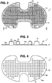
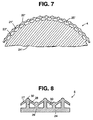
- a preformed ceramic pattern 1, of the present invention in the form of a lattice element, for a porous ingrowth surface of an orthopedic implant, such as that for a femoral which is shown in Figure 7.
- Pattern 1 may be prepared by injection molding in any known manner. Pattern 1 as shown in Figure 1-4 would be useful for a tibial or knee fibial implant. The shape of the pattern may be changed to conform to the shape of implants for other indications such as hip or femoral knee components.
- Pattern 1 consists of a flat ceramic sheet 12 comprising transverse, generally perpendicular, grooves 13a and 13b, intersecting at holes 14, corresponding to connectors 23' of the implant in Figure 7, in a first surface 16 of said sheet, which space connectors 13a' and 13b' from the base 24' of the implant.
- the pattern comprises projections 15 perpendicular to surface 16, for aligning the pattern in a meltable material investment mold such as is shown schematically in Figure 5B and designated with the numeral 2.
- a preferred ceramic pattern for a portion of a porous surface is shown schematically in Figure 5A and designated 3.
- the pattern which may be formed by known methods, such as injection molding, comprises a flat ceramic sheet 12a comprising generally perpendicular grooves 13a' and 13b' which intersected holes 14a, through the ceramic sheet 12a.
- the insert also comprises protrusions 15, perpendicular to the surface of the ceramic sheet 12 which aid in aligning the insert in a meltable composition die such as is shown schematically in Figure 5B and designated 2.
- the die comprises two releaseably joinable sections, designated 2a and 2b.
- Section 2a comprises intersecting grooves 13'' and 13b'' which, upon emplacement of the pattern 3 in the die form elongated cavities corresponding to the connectors 21 and 22 of implant 4 in Figure 6D.
- the second section 2b comprises a cavity 16 a portion 31 of which, that is left over after emplacement of the pattern 3 therein as shown in Figure 5C, corresponds to the base 24 of the implant.
- the colloidal silica is selected from the group including refractory powders of zirconia, alumina and silica and is applied to the meltable casting as a slurry.
- the first coat of the slurry used to form the shell in the investment casting process is critical.
- a preferred slurry for this first coat is a colloidal silica binder (such as Du Pont's 30% colloidal binder) base with refractory zirconia and silica flours.
- the viscosity can be varied by adding more or less binder.
- the dip pattern must be designed to make sure that the one-piece casting is completely and evenly coated.
- the integral cast lattice element forming a tissue ingrowth surface comprising connectors 21' and 22', can be easily produced on the outside of a femoral component of a hip prosthesis.
- This is accomplished by producing a spherical preformed ceramic core that replicates the outer surface 24'' of the hip prosthesis utilizing a meltable material formulation, such as wax or polystyrene, which is suitably flexible and can be wrapped around the outer surface of a hip prosthesis.
- a wax is Yates JW-2® (Yates Manufacturing Co., Chicago, IL 60608) wax.
- the mold of Figure 6B may be prepared by the process of Direct Shell Production CastingTM (Soligen, Inc., Northridge, CA.)
- the porous surface of the implant is not uniformly spaced from the base.
- alternate rows of spacers 28 and 29, in the implant have different heights thus resulting in differing displacements of the connectors 27 from the base 29 and varying forms of the pores 30.
- alternate spacers rather than rows of spacers, may have varying heights.
Landscapes
- Health & Medical Sciences (AREA)
- Life Sciences & Earth Sciences (AREA)
- Public Health (AREA)
- Veterinary Medicine (AREA)
- Oral & Maxillofacial Surgery (AREA)
- Transplantation (AREA)
- Orthopedic Medicine & Surgery (AREA)
- Animal Behavior & Ethology (AREA)
- General Health & Medical Sciences (AREA)
- Biomedical Technology (AREA)
- Chemical & Material Sciences (AREA)
- Vascular Medicine (AREA)
- Heart & Thoracic Surgery (AREA)
- Engineering & Computer Science (AREA)
- Cardiology (AREA)
- Inorganic Chemistry (AREA)
- Physical Education & Sports Medicine (AREA)
- Dermatology (AREA)
- Medicinal Chemistry (AREA)
- Epidemiology (AREA)
- Prostheses (AREA)
- Materials For Medical Uses (AREA)
- Molds, Cores, And Manufacturing Methods Thereof (AREA)
Abstract
Description
Claims (21)
- A mold (2, 3) for use in preparing a one-piece, cast metal prosthetic bone implant (4), the implant having a base (24) and a porous ingrowth surface, the porous ingrowth surface having a lattice element (33) with intersecting elongated connecting members (21, 22) spaced from the base by spacing elements (23) that connect the base and the lattice element, the mold comprising(a) a preformed ceramic pattern (3), the pattern comprising a ceramic sheet (12a) having on a first surface thereof a plurality of intersecting grooves (13a', 13b'), holes (14) at the intersections of said grooves and protrusions (15) from the first surface; and(b) a meltable composition investment die (2), the die having cavities (15') capable of receiving the protrusions (15) in order to aid alignment of the pattern in the die, a cavity (16) and grooves (13a'', 13b''):
the intersecting grooves (13a', 13b') and the grooves (13a'', 13b'') being of complementary dimension and arrangement such that when the pattern is placed in the die and the protrusions are received in the cavities, the grooves together form elongated cavities that are capable of forming the connecting members, the holes are capable of forming the spacing elements and the cavity is capable of forming the base. - A mold as claimed in claim 1 wherein the intersecting grooves are not parallel.
- A mold as claimed in claim 1 wherein the holes are of equal length.
- A mold as claimed in claim 1 wherein the holes are of unequal length.
- A mold as claimed in any one of the preceding claims wherein the meltable composition investment die is a wax investment die.
- A process for preparing a one-piece, cast metal prosthetic bone implant (4) as defined in claim 1 comprisingadding a meltable composition (20) in molten form to a mold (2, 3) as claimed in claim 1,allowing the meltable composition to cool and solidify to form a meltable composition casting of the implant,removing the meltable composition casting containing the preformed ceramic pattern (3) from the investment die (2),coating the casting containing the preformed ceramic pattern with a ceramic material,removing the meltable composition from the ceramic material by melting the composition to provide a ceramic mold (19) containing the preformed ceramic pattern,adding molten metal to the ceramic mold containing the preformed ceramic pattern,allowing the metal to cool and solidify to form the implant andremoving the ceramic material and the preformed ceramic pattern to provide the implant.
- A process as claimed in claim 6 wherein the ceramic pattern is removed from the implant by leaching with a base.
- A process as claimed in claim 6 or 7 wherein the metal is a cobalt-chrome alloy.
- A process as claimed in any one of claims 6 to 8 wherein the meltable composition is a wax or thermoplastic polymer.
- A process as claimed in claim 9 wherein the meltable composition is a wax.
- A process as claimed in claim 9 wherein the meltable composition is a polystyrene.
- A process as claimed in any one of claims 6 to 11 wherein the preformed ceramic pattern is comprised of a ceramic material selected from fused silica and alumina.
- A process as claimed in claim 12 wherein the ceramic material is fused silica.
- A process as claimed in any one of claims 6, 7 and 9 to 13 wherein the metal is selected from Vitallium, titanium, tantalum and alloys thereof.
- A process as claimed in claim 14 wherein the metal is Vitallium.
- A process as claimed in claim 14 wherein the metal is titanium or an alloy thereof.
- A process as claimed in claim 14 wherein the metal is tantalum or an alloy thereof.
- A process for preparing a ceramic mold for a one-piece, cast metal bone implant as defined in claim 1 comprisingcreating the design for the ceramic mold on a computer andconverting the design into the ceramic mold containing patterns of the base and of the spacing elements and the connecting members of the lattice element of the implant under computer control, one layer at a time, by spreading ceramic powder then printing it with a liquid binder and removing excess powder.
- A preformed ceramic pattern (3) as defined in claim 1.
- A pattern as claimed in claim 19 which is comprised of a ceramic material selected from fused silica or alumina.
- A pattern as claimed in claim 20 wherein the ceramic material is fused silica.
Applications Claiming Priority (3)
| Application Number | Priority Date | Filing Date | Title |
|---|---|---|---|
| US08/146,281 US5524695A (en) | 1993-10-29 | 1993-10-29 | Cast bone ingrowth surface |
| US146281 | 1993-10-29 | ||
| PCT/IB1994/000286 WO1995011639A1 (en) | 1993-10-29 | 1994-09-21 | Cast bone ingrowth surface |
Publications (2)
| Publication Number | Publication Date |
|---|---|
| EP0725606A1 EP0725606A1 (en) | 1996-08-14 |
| EP0725606B1 true EP0725606B1 (en) | 1999-12-01 |
Family
ID=22516646
Family Applications (1)
| Application Number | Title | Priority Date | Filing Date |
|---|---|---|---|
| EP94925601A Expired - Lifetime EP0725606B1 (en) | 1993-10-29 | 1994-09-21 | Cast bone ingrowth surface |
Country Status (8)
| Country | Link |
|---|---|
| US (1) | US5524695A (en) |
| EP (1) | EP0725606B1 (en) |
| JP (1) | JP2984375B2 (en) |
| AT (1) | ATE187055T1 (en) |
| AU (1) | AU686221B2 (en) |
| CA (1) | CA2172250C (en) |
| DE (2) | DE69421935T2 (en) |
| WO (1) | WO1995011639A1 (en) |
Cited By (12)
| Publication number | Priority date | Publication date | Assignee | Title |
|---|---|---|---|---|
| US9579714B1 (en) | 2015-12-17 | 2017-02-28 | General Electric Company | Method and assembly for forming components having internal passages using a lattice structure |
| US9968991B2 (en) | 2015-12-17 | 2018-05-15 | General Electric Company | Method and assembly for forming components having internal passages using a lattice structure |
| US9987677B2 (en) | 2015-12-17 | 2018-06-05 | General Electric Company | Method and assembly for forming components having internal passages using a jacketed core |
| US10046389B2 (en) | 2015-12-17 | 2018-08-14 | General Electric Company | Method and assembly for forming components having internal passages using a jacketed core |
| US10099276B2 (en) | 2015-12-17 | 2018-10-16 | General Electric Company | Method and assembly for forming components having an internal passage defined therein |
| US10099284B2 (en) | 2015-12-17 | 2018-10-16 | General Electric Company | Method and assembly for forming components having a catalyzed internal passage defined therein |
| US10099283B2 (en) | 2015-12-17 | 2018-10-16 | General Electric Company | Method and assembly for forming components having an internal passage defined therein |
| US10118217B2 (en) | 2015-12-17 | 2018-11-06 | General Electric Company | Method and assembly for forming components having internal passages using a jacketed core |
| US10137499B2 (en) | 2015-12-17 | 2018-11-27 | General Electric Company | Method and assembly for forming components having an internal passage defined therein |
| US10150158B2 (en) | 2015-12-17 | 2018-12-11 | General Electric Company | Method and assembly for forming components having internal passages using a jacketed core |
| US10286450B2 (en) | 2016-04-27 | 2019-05-14 | General Electric Company | Method and assembly for forming components using a jacketed core |
| US10335853B2 (en) | 2016-04-27 | 2019-07-02 | General Electric Company | Method and assembly for forming components using a jacketed core |
Families Citing this family (21)
| Publication number | Priority date | Publication date | Assignee | Title |
|---|---|---|---|---|
| CA2142636C (en) * | 1994-02-18 | 2005-09-20 | Salvatore Caldarise | Implantable articles with as-cast macrotextured surface regions and method of manufacturing the same |
| US5665118A (en) * | 1994-02-18 | 1997-09-09 | Johnson & Johnson Professional, Inc. | Bone prostheses with direct cast macrotextured surface regions and method for manufacturing the same |
| CA2142634C (en) * | 1994-02-18 | 2005-09-20 | Salvatore Caldarise | Self-lubricating implantable articulation member |
| US6105235A (en) * | 1994-04-28 | 2000-08-22 | Johnson & Johnson Professional, Inc. | Ceramic/metallic articulation component and prosthesis |
| US6209621B1 (en) | 1995-07-07 | 2001-04-03 | Depuy Orthopaedics, Inc. | Implantable prostheses with metallic porous bead preforms applied during casting and method of forming the same |
| DE19614949A1 (en) * | 1996-04-16 | 1997-10-23 | Horst Broziat | Bone implant |
| US5906234A (en) * | 1996-10-22 | 1999-05-25 | Johnson & Johnson Professional, Inc. | Investment casting |
| US6786982B2 (en) | 2000-01-10 | 2004-09-07 | General Electric Company | Casting having an enhanced heat transfer, surface, and mold and pattern for forming same |
| US6302185B1 (en) * | 2000-01-10 | 2001-10-16 | General Electric Company | Casting having an enhanced heat transfer surface, and mold and pattern for forming same |
| US6502622B2 (en) * | 2001-05-24 | 2003-01-07 | General Electric Company | Casting having an enhanced heat transfer, surface, and mold and pattern for forming same |
| KR100475352B1 (en) * | 2001-11-21 | 2005-03-10 | 배순순 | Method of a waterway |
| US6726086B2 (en) * | 2002-01-24 | 2004-04-27 | Siemens Westinghouse Power Corporation | Liquid phase diffusion bonding to a superalloy component |
| US7641985B2 (en) * | 2004-06-21 | 2010-01-05 | Siemens Energy, Inc. | Boron free joint for superalloy component |
| US20070055373A1 (en) * | 2005-09-08 | 2007-03-08 | Zimmer Spine, Inc. | Facet replacement/spacing and flexible spinal stabilization |
| NL1030364C2 (en) * | 2005-11-07 | 2007-05-08 | Ft Innovations Fti B V | Implant and method for manufacturing such an implant. |
| US9327056B2 (en) | 2006-02-14 | 2016-05-03 | Washington State University | Bone replacement materials |
| US8916198B2 (en) | 2006-04-25 | 2014-12-23 | Washington State University | Mesoporous calcium silicate compositions and methods for synthesis of mesoporous calcium silicate for controlled release of bioactive agents |
| WO2007124511A2 (en) | 2006-04-25 | 2007-11-01 | Washington State University | Resorbable ceramics with controlled strength loss rates |
| GB0809721D0 (en) * | 2008-05-28 | 2008-07-02 | Univ Bath | Improvements in or relating to joints and/or implants |
| WO2012071500A1 (en) * | 2010-11-23 | 2012-05-31 | Richard Berger | Spacer apparatus and method for achieving improved fit and balance in knee joints |
| US12329629B2 (en) | 2021-06-08 | 2025-06-17 | Howmedica Osteonics Corp. | Additive manufacturing of porous coatings separate from substrate |
Citations (1)
| Publication number | Priority date | Publication date | Assignee | Title |
|---|---|---|---|---|
| EP0420542A1 (en) * | 1989-09-28 | 1991-04-03 | Howmedica Inc. | Cast bone ingrowth surface |
Family Cites Families (8)
| Publication number | Priority date | Publication date | Assignee | Title |
|---|---|---|---|---|
| DE3224265C2 (en) * | 1982-06-28 | 1987-01-08 | S + G Implants GmbH, 2400 Lübeck | Method for producing an implant as a bone substitute |
| US4722870A (en) * | 1985-01-22 | 1988-02-02 | Interpore International | Metal-ceramic composite material useful for implant devices |
| FR2594727B1 (en) * | 1986-02-27 | 1988-05-06 | Snecma | PROCESS FOR THE PREPARATION OF CERAMIC CORES |
| DE3626549A1 (en) * | 1986-08-06 | 1988-02-11 | Mecron Med Prod Gmbh | METHOD FOR PRODUCING AN ENDOPROTHESIS WITH INDIVIDUAL ADAPTATION |
| DE3715000A1 (en) * | 1987-05-06 | 1988-11-17 | Krupp Gmbh | JOINT PROSTHESIS AND METHOD FOR THEIR PRODUCTION |
| DE3844155C2 (en) * | 1988-12-23 | 1994-01-27 | Johnson & Johnson Professional | Endoprosthesis and process for its manufacture |
| DE3923418C2 (en) * | 1989-07-12 | 1995-11-30 | Rolf Prof Dr Miehlke | Endoprosthesis |
| DE3928394A1 (en) * | 1989-08-28 | 1991-03-21 | Eska Medical Gmbh & Co | METHOD FOR PRODUCING AN IMPLANT WITH ITS SURFACE AT LEAST PARTLY COVERING METALLIC OPEN-CELLED STRUCTURE |
-
1993
- 1993-10-29 US US08/146,281 patent/US5524695A/en not_active Expired - Fee Related
-
1994
- 1994-09-21 EP EP94925601A patent/EP0725606B1/en not_active Expired - Lifetime
- 1994-09-21 CA CA002172250A patent/CA2172250C/en not_active Expired - Fee Related
- 1994-09-21 AT AT94925601T patent/ATE187055T1/en not_active IP Right Cessation
- 1994-09-21 DE DE69421935T patent/DE69421935T2/en not_active Expired - Fee Related
- 1994-09-21 JP JP7504784A patent/JP2984375B2/en not_active Expired - Lifetime
- 1994-09-21 WO PCT/IB1994/000286 patent/WO1995011639A1/en not_active Ceased
- 1994-09-21 AU AU75456/94A patent/AU686221B2/en not_active Ceased
- 1994-09-21 DE DE9490333U patent/DE9490333U1/en not_active Expired - Lifetime
Patent Citations (1)
| Publication number | Priority date | Publication date | Assignee | Title |
|---|---|---|---|---|
| EP0420542A1 (en) * | 1989-09-28 | 1991-04-03 | Howmedica Inc. | Cast bone ingrowth surface |
Cited By (13)
| Publication number | Priority date | Publication date | Assignee | Title |
|---|---|---|---|---|
| US9579714B1 (en) | 2015-12-17 | 2017-02-28 | General Electric Company | Method and assembly for forming components having internal passages using a lattice structure |
| US9968991B2 (en) | 2015-12-17 | 2018-05-15 | General Electric Company | Method and assembly for forming components having internal passages using a lattice structure |
| US9975176B2 (en) | 2015-12-17 | 2018-05-22 | General Electric Company | Method and assembly for forming components having internal passages using a lattice structure |
| US9987677B2 (en) | 2015-12-17 | 2018-06-05 | General Electric Company | Method and assembly for forming components having internal passages using a jacketed core |
| US10046389B2 (en) | 2015-12-17 | 2018-08-14 | General Electric Company | Method and assembly for forming components having internal passages using a jacketed core |
| US10099276B2 (en) | 2015-12-17 | 2018-10-16 | General Electric Company | Method and assembly for forming components having an internal passage defined therein |
| US10099284B2 (en) | 2015-12-17 | 2018-10-16 | General Electric Company | Method and assembly for forming components having a catalyzed internal passage defined therein |
| US10099283B2 (en) | 2015-12-17 | 2018-10-16 | General Electric Company | Method and assembly for forming components having an internal passage defined therein |
| US10118217B2 (en) | 2015-12-17 | 2018-11-06 | General Electric Company | Method and assembly for forming components having internal passages using a jacketed core |
| US10137499B2 (en) | 2015-12-17 | 2018-11-27 | General Electric Company | Method and assembly for forming components having an internal passage defined therein |
| US10150158B2 (en) | 2015-12-17 | 2018-12-11 | General Electric Company | Method and assembly for forming components having internal passages using a jacketed core |
| US10286450B2 (en) | 2016-04-27 | 2019-05-14 | General Electric Company | Method and assembly for forming components using a jacketed core |
| US10335853B2 (en) | 2016-04-27 | 2019-07-02 | General Electric Company | Method and assembly for forming components using a jacketed core |
Also Published As
| Publication number | Publication date |
|---|---|
| AU686221B2 (en) | 1998-02-05 |
| JP2984375B2 (en) | 1999-11-29 |
| CA2172250A1 (en) | 1995-05-04 |
| CA2172250C (en) | 2000-01-04 |
| DE69421935T2 (en) | 2000-07-20 |
| DE69421935D1 (en) | 2000-01-05 |
| AU7545694A (en) | 1995-05-22 |
| WO1995011639A1 (en) | 1995-05-04 |
| EP0725606A1 (en) | 1996-08-14 |
| DE9490333U1 (en) | 1996-08-01 |
| ATE187055T1 (en) | 1999-12-15 |
| US5524695A (en) | 1996-06-11 |
| JPH08510944A (en) | 1996-11-19 |
Similar Documents
| Publication | Publication Date | Title |
|---|---|---|
| CA2172250C (en) | Cast bone ingrowth surface | |
| US5108435A (en) | Cast bone ingrowth surface | |
| US5713410A (en) | Bone prostheses with direct cast macrotextured surface regions and method for manufacturing the same | |
| CA2142636C (en) | Implantable articles with as-cast macrotextured surface regions and method of manufacturing the same | |
| US5762125A (en) | Custom bioimplantable article | |
| KR101904030B1 (en) | Implant components and methods | |
| CN102821716B (en) | Prosthese | |
| EP3412252B1 (en) | Polymer interlock support structure | |
| AU2019246736B2 (en) | Hybrid fixation features for three-dimensional porous structures for bone ingrowth and methods for producing | |
| JPH05508561A (en) | artificial implant | |
| US20080228269A1 (en) | Moulded article and mass and method for production thereof | |
| AU2010284207A1 (en) | Porous implant structures | |
| Holtzhausen et al. | Additive manufacturing of individual bone implants made of bioresorbable calcium phosphate cement using the example of large skull defects | |
| HK1120745A (en) | Moulded article and mass and method for production thereof |
Legal Events
| Date | Code | Title | Description |
|---|---|---|---|
| PUAI | Public reference made under article 153(3) epc to a published international application that has entered the european phase |
Free format text: ORIGINAL CODE: 0009012 |
|
| 17P | Request for examination filed |
Effective date: 19960322 |
|
| AK | Designated contracting states |
Kind code of ref document: A1 Designated state(s): AT CH DE FR GB IE IT LI |
|
| 17Q | First examination report despatched |
Effective date: 19970515 |
|
| GRAG | Despatch of communication of intention to grant |
Free format text: ORIGINAL CODE: EPIDOS AGRA |
|
| GRAG | Despatch of communication of intention to grant |
Free format text: ORIGINAL CODE: EPIDOS AGRA |
|
| GRAG | Despatch of communication of intention to grant |
Free format text: ORIGINAL CODE: EPIDOS AGRA |
|
| GRAH | Despatch of communication of intention to grant a patent |
Free format text: ORIGINAL CODE: EPIDOS IGRA |
|
| GRAH | Despatch of communication of intention to grant a patent |
Free format text: ORIGINAL CODE: EPIDOS IGRA |
|
| RAP1 | Party data changed (applicant data changed or rights of an application transferred) |
Owner name: STRYKER TECHNOLOGIES CORPORATION |
|
| GRAA | (expected) grant |
Free format text: ORIGINAL CODE: 0009210 |
|
| AK | Designated contracting states |
Kind code of ref document: B1 Designated state(s): AT CH DE FR GB IE IT LI |
|
| PG25 | Lapsed in a contracting state [announced via postgrant information from national office to epo] |
Ref country code: LI Free format text: LAPSE BECAUSE OF FAILURE TO SUBMIT A TRANSLATION OF THE DESCRIPTION OR TO PAY THE FEE WITHIN THE PRESCRIBED TIME-LIMIT Effective date: 19991201 Ref country code: CH Free format text: LAPSE BECAUSE OF FAILURE TO SUBMIT A TRANSLATION OF THE DESCRIPTION OR TO PAY THE FEE WITHIN THE PRESCRIBED TIME-LIMIT Effective date: 19991201 Ref country code: AT Free format text: LAPSE BECAUSE OF FAILURE TO SUBMIT A TRANSLATION OF THE DESCRIPTION OR TO PAY THE FEE WITHIN THE PRESCRIBED TIME-LIMIT Effective date: 19991201 |
|
| REF | Corresponds to: |
Ref document number: 187055 Country of ref document: AT Date of ref document: 19991215 Kind code of ref document: T |
|
| REG | Reference to a national code |
Ref country code: CH Ref legal event code: EP |
|
| REF | Corresponds to: |
Ref document number: 69421935 Country of ref document: DE Date of ref document: 20000105 |
|
| REG | Reference to a national code |
Ref country code: IE Ref legal event code: FG4D |
|
| ITF | It: translation for a ep patent filed | ||
| ET | Fr: translation filed | ||
| REG | Reference to a national code |
Ref country code: CH Ref legal event code: PL |
|
| PLBE | No opposition filed within time limit |
Free format text: ORIGINAL CODE: 0009261 |
|
| STAA | Information on the status of an ep patent application or granted ep patent |
Free format text: STATUS: NO OPPOSITION FILED WITHIN TIME LIMIT |
|
| 26N | No opposition filed | ||
| REG | Reference to a national code |
Ref country code: GB Ref legal event code: IF02 |
|
| PGFP | Annual fee paid to national office [announced via postgrant information from national office to epo] |
Ref country code: IE Payment date: 20020722 Year of fee payment: 9 |
|
| PGFP | Annual fee paid to national office [announced via postgrant information from national office to epo] |
Ref country code: GB Payment date: 20020808 Year of fee payment: 9 |
|
| PGFP | Annual fee paid to national office [announced via postgrant information from national office to epo] |
Ref country code: FR Payment date: 20020903 Year of fee payment: 9 |
|
| PGFP | Annual fee paid to national office [announced via postgrant information from national office to epo] |
Ref country code: DE Payment date: 20020930 Year of fee payment: 9 |
|
| PG25 | Lapsed in a contracting state [announced via postgrant information from national office to epo] |
Ref country code: GB Free format text: LAPSE BECAUSE OF NON-PAYMENT OF DUE FEES Effective date: 20030921 |
|
| PG25 | Lapsed in a contracting state [announced via postgrant information from national office to epo] |
Ref country code: IE Free format text: LAPSE BECAUSE OF NON-PAYMENT OF DUE FEES Effective date: 20030922 |
|
| PG25 | Lapsed in a contracting state [announced via postgrant information from national office to epo] |
Ref country code: DE Free format text: LAPSE BECAUSE OF NON-PAYMENT OF DUE FEES Effective date: 20040401 |
|
| GBPC | Gb: european patent ceased through non-payment of renewal fee |
Effective date: 20030921 |
|
| PG25 | Lapsed in a contracting state [announced via postgrant information from national office to epo] |
Ref country code: FR Free format text: LAPSE BECAUSE OF NON-PAYMENT OF DUE FEES Effective date: 20040528 |
|
| REG | Reference to a national code |
Ref country code: IE Ref legal event code: MM4A |
|
| REG | Reference to a national code |
Ref country code: FR Ref legal event code: ST |
|
| PG25 | Lapsed in a contracting state [announced via postgrant information from national office to epo] |
Ref country code: IT Free format text: LAPSE BECAUSE OF NON-PAYMENT OF DUE FEES;WARNING: LAPSES OF ITALIAN PATENTS WITH EFFECTIVE DATE BEFORE 2007 MAY HAVE OCCURRED AT ANY TIME BEFORE 2007. THE CORRECT EFFECTIVE DATE MAY BE DIFFERENT FROM THE ONE RECORDED. Effective date: 20050921 |