EP0724826B1 - A flowerpot - Google Patents
A flowerpot Download PDFInfo
- Publication number
- EP0724826B1 EP0724826B1 EP19960200120 EP96200120A EP0724826B1 EP 0724826 B1 EP0724826 B1 EP 0724826B1 EP 19960200120 EP19960200120 EP 19960200120 EP 96200120 A EP96200120 A EP 96200120A EP 0724826 B1 EP0724826 B1 EP 0724826B1
- Authority
- EP
- European Patent Office
- Prior art keywords
- flowerpot
- wall
- hole
- bottom part
- slots
- Prior art date
- Legal status (The legal status is an assumption and is not a legal conclusion. Google has not performed a legal analysis and makes no representation as to the accuracy of the status listed.)
- Expired - Lifetime
Links
- 238000000034 method Methods 0.000 claims description 14
- 238000000465 moulding Methods 0.000 claims description 8
- XLYOFNOQVPJJNP-UHFFFAOYSA-N water Substances O XLYOFNOQVPJJNP-UHFFFAOYSA-N 0.000 description 10
- 239000000463 material Substances 0.000 description 6
- 239000004033 plastic Substances 0.000 description 5
- 230000008719 thickening Effects 0.000 description 5
- 238000001746 injection moulding Methods 0.000 description 3
- 101100298222 Caenorhabditis elegans pot-1 gene Proteins 0.000 description 2
- 238000004519 manufacturing process Methods 0.000 description 2
- 238000009987 spinning Methods 0.000 description 2
- 239000004743 Polypropylene Substances 0.000 description 1
- 238000009826 distribution Methods 0.000 description 1
- 238000002474 experimental method Methods 0.000 description 1
- -1 polypropylene Polymers 0.000 description 1
- 229920001155 polypropylene Polymers 0.000 description 1
- 230000007704 transition Effects 0.000 description 1
Images

Classifications
-
- A—HUMAN NECESSITIES
- A01—AGRICULTURE; FORESTRY; ANIMAL HUSBANDRY; HUNTING; TRAPPING; FISHING
- A01G—HORTICULTURE; CULTIVATION OF VEGETABLES, FLOWERS, RICE, FRUIT, VINES, HOPS OR SEAWEED; FORESTRY; WATERING
- A01G9/00—Cultivation in receptacles, forcing-frames or greenhouses; Edging for beds, lawn or the like
- A01G9/02—Receptacles, e.g. flower-pots or boxes; Glasses for cultivating flowers
- A01G9/021—Pots formed in one piece; Materials used therefor
Definitions
- the invention relates to a flowerpot comprising a tubular section extending around a central axis and a bottom part extending transversely to said central axis and being connected to one end of said tubular section, said bottom part being provided with slots extending substantially radially to the outer side of the pot, said slots being present on a side of the bottom part facing away from said section, whereby a slot is bounded by side walls extending substantially axially and radially, which are interconnected at a side facing said section by means of an upper wall, and whereby each side wall is connected to a side wall of a neighbouring slot by means of a bottom wall comprising a hole.
- ribs are positioned on a side facing away from said section, between the hole in the bottom wall and the outer side of the pot or a slot. Said ribs keep the bottom wall spaced from a foundation on which the pot is supported and form a passage from said hole to said outer side of the pot or to said slot. Via said passage water or air can flow into or out of the pot.
- a drawback of such ribs is that they constitute local thickenings of the material.
- the ribs are for example formed as local thickenings during the injection moulding process. With thickenings of this kind problems may occur with regard to the curing of the plastic material. Local thickenings cannot occur when a different manufacturing technique, such as a thermo-moulding technique, is used and consequently a flowerpot according to the aforesaid patent application cannot be produced by means of a thermo-moulding technique.
- This technique is being used to an increasing extent, as it is possible with this technique to manufacture flowerpots having thinner walls in a simple manner, as a result of which less plastic material is required for producing a flowerpot.
- a further drawback of such ribs is that the flowerpot exhibits relatively little stability, since the flowerpot may tilt over the ribs and subsequently fall over.
- the object of the present invention is to provide a flowerpot which is provided with a passage from a hole in the bottom wall to the outer side of the pot or to a slot, whereby the presence of a local thickening in the flowerpot is avoided and a relatively stable flowerpot is obtained.
- a flowerpot of this type may exhibit a uniform wall thickness, and it is suitable for being produced by means of a thermo-moulding technique.
- the connecting wall keeps the sloping wall spaced apart from a plane in which the remaining part of the bottom wall extends.
- One embodiment of the flowerpot according to the invention is characterized in that, seen in axial direction, the connecting wall is larger on a side located near the outer side of the flowerpot than on a side located near said hole.
- Yet another embodiment of a flowerpot according to the invention is characterized in that said flowerpot comprises five slots.
- Another embodiment of the flowerpot according to the invention is characterized in that the pot is made by means of a thermo-moulding technique.
- Such a technique is environmentally friendly, as in comparison with an injection moulding technique relatively little plastic material is required for making such a flowerpot.
- Yet another embodiment of the flowerpot according to the invention is characterized in that a central part of the bottom part located near the central axis can be moved against spring force in a direction away from the tubular section.
- Figure 1 shows a flowerpot 1 according to the invention, which is provided with a tubular section 3 extending about central axis 2, and with a bottom part 4 connected thereto.
- the tubular section 3 comprises a cylindrical part 5 and a flange 6 secured to one end thereof, said flange extending transversely to the central axis and constituting a stiffening for the cylindrical part 5.
- Bottom part 4 is connected, via a receding edge 7, to an end of the cylindrical part 5 facing away from flange 6.
- Each slot 8 is bounded by substantially radially and axially extending side walls 9, which are interconnected, on a side directed towards section 3, by an upper wall 10.
- Each side wall is connected to a side wall of a neighbouring slot 8 by means of a bottom wall 11.
- the side walls 9 are slightly inclined, resulting in a trapezoidal cross-section of a slot 8.
- the slots 8 all extend from the central axis 2, as a result of which a common open part 12 is formed near the central axis.
- a central part comprising said open part 12 and adjacent parts of the bottom and upper walls is recessed with respect to the outer side 13 of the flowerpot. As a result of this the central part is biased in that direction, as it were.
- the bottom part 4 of the flowerpot 1 will not sag to the extent that the flower pot 1 would only be supported on the parts of the bottom walls 11 located near the central part, however, in which position undesirable spinning of the flowerpot 1 may occur.
- holes may be provided in the upper and bottom walls 10, 11 for the supply and discharge of water and air. The holes are not shown in Figure 1.
- the five slots 8 in the bottom part 4 provide the flowerpot with an optimum stability and leave sufficient space for forming holes having a desired minimum width of 9 mm, for example.
- the illustrated flowerpot 1 may be formed of plastic material by means of a thermo-moulding technique or an injection moulding technique.
- FIG. 2 shows a second embodiment of a flowerpot 1 according to the invention, which largely corresponds with the flowerpot 1 shown in Figure 1. Accordingly only the differences will be discussed herein.
- the bottom part 1 is provided with ten regularly spaced-apart holes 14 arranged so as to form a circle, whereby each bottom wall and each upper wall is provided with one hole 14.
- each bottom wall 11 is provided with a channel 15, which extends from said hole 14 to the outer side of the flowerpot 1.
- Channel 15 is bounded by radially and axially extending connecting walls 16 and a sloping wall 17 positioned between said connecting walls. Near the outer side 13 the connecting walls 16 are larger, seen in axial direction, than near hole 14, as a result of which the sloping wall 17 slopes down to hole 14.
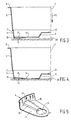
- FIGs 3 and 4 are sectional views, taken along line III - III, of the flowerpot 1 shown in Figure 2, showing a flowerpot 1 in unloaded and loaded condition respectively, that is, without and with earth and plants present therein.
- the central part in unloaded condition the central part is located further away from the foundation 20 than the outer side 13 of the flowerpot 1.
- the flowerpot 1 is biased, as it were.
- the flowerpot 1 rests firmly on the foundation 20 with the outer edges of the bottom walls 11.
- the central part 12 has sagged in the direction of arrow P1 against the spring force of the plastic material, and the bottom walls 11 abut against the foundation 20 near the central part. Sloping wall 17 slopes down from the outer side 13 towards hole 14.
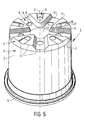
- FIG. 6 shows a third embodiment of a flowerpot according to the invention.
- the flowerpot 1 is provided with connecting walls 16 extending tangentially to the hole, said connecting walls beginning at the level of the centre of the hole and tapering outwardly towards the outside. As a result of this configuration there is no stepped transition from the edge of the hole to the sloping wall 17.
- the channel 17 may also be connected to a neighbouring slot 8.
- the flowerpot may be made of polypropylene by using a thermo-moulding technique.
- tubular section 3 may also be square, hexagonal or octagonal.
- the flowerpot comprising five slots 8 has an optimum hole pattern for a uniform drainage of the bottom part 4. Furthermore it exhibits a relatively great resilience and stability.
- a bottom part comprising five slots has greater resilience than a bottom part comprising for example three slots.
Landscapes
- Life Sciences & Earth Sciences (AREA)
- Environmental Sciences (AREA)
- Cultivation Receptacles Or Flower-Pots, Or Pots For Seedlings (AREA)
- Sewage (AREA)
Description
Claims (7)
- A flowerpot (1) comprising a tubular section (3) extending around a central axis (2) and a bottom part (4) extending transversely to said central axis (2) and being connected to one end of said tubular section (3), said bottom part (4) being provided with slots (8) extending substantially radially to the outer side of the pot (1), said slots (8) being present on a side of the bottom part (4) facing away from said section (3), whereby a slot (8) is bounded by side walls (9) extending substantially axially and radially with respect to the central axis, which walls (9) are interconnected at a side facing said section (3) by means of a wall (10), and whereby each side wall (9) at a side facing away from said section (3) is connected to a side wall (9) of a neighbouring slot (8) by means of a bottom wall (11) comprising a hole (14), characterized in that the bottom wall (11) is provided with a channel (15) extending from the hole (14) to the outer side of the pot (1) or to a neighbouring slot (8), said channel (15) being located on a side of the bottom part (4) facing away from the section (3) and being bounded by connecting walls (16) extending from an edge of the hole (14) in an at least substantially axially direction with respect to the axis of the hole (14) and by a sloping wall (17) connected to said connecting walls (16).
- A flowerpot according to claim 1, characterized in that, seen in axial direction, the connecting wall (16) is larger on a side located near the outer side of the flowerpot (1) than on a side located near said hole (14).
- A flowerpot according to any one of the preceding claims, characterized in that said flowerpot (1) comprises five slots (8).
- A flowerpot according to any one of the preceding claims, characterized in that the pot (1) is made by means of a thermo-moulding technique.
- A flowerpot according to any one of the preceding claims, characterized in that a central part of the bottom part (4) located near the central axis (2) is movable against spring force in a direction away from said tubular section (3).
- A flowerpot according to any one of the preceding claims, characterized in that said slots (8) extend from said central axis (2) to the outer side of the flowerpot (1).
- A flowerpot according to any one of the preceding claims, characterized in that said wall (10) is provided with a hole (12).
Applications Claiming Priority (2)
| Application Number | Priority Date | Filing Date | Title |
|---|---|---|---|
| NL9500175A NL9500175A (en) | 1995-02-01 | 1995-02-01 | Flowerpot. |
| NL9500175 | 1995-02-01 |
Publications (2)
| Publication Number | Publication Date |
|---|---|
| EP0724826A1 EP0724826A1 (en) | 1996-08-07 |
| EP0724826B1 true EP0724826B1 (en) | 2000-04-26 |
Family
ID=19865523
Family Applications (1)
| Application Number | Title | Priority Date | Filing Date |
|---|---|---|---|
| EP19960200120 Expired - Lifetime EP0724826B1 (en) | 1995-02-01 | 1996-01-18 | A flowerpot |
Country Status (5)
| Country | Link |
|---|---|
| EP (1) | EP0724826B1 (en) |
| DE (1) | DE69607871T2 (en) |
| DK (1) | DK0724826T3 (en) |
| ES (1) | ES2147891T3 (en) |
| NL (1) | NL9500175A (en) |
Cited By (1)
| Publication number | Priority date | Publication date | Assignee | Title |
|---|---|---|---|---|
| US9271486B2 (en) | 2011-11-10 | 2016-03-01 | James J. Messina | Combination animal repellents |
Families Citing this family (20)
| Publication number | Priority date | Publication date | Assignee | Title |
|---|---|---|---|---|
| DE19801141A1 (en) | 1998-01-14 | 1999-07-15 | Erich Lehmann | Device for cultivating plants |
| DE29918043U1 (en) * | 1999-10-12 | 2000-02-10 | Gebr. Pöppelmann, Kunststoffwerk-Werkzeugbau, 49393 Lohne | Plant pot made of thermoformed plastic film |
| GB2356787A (en) * | 1999-10-29 | 2001-06-06 | Christopher Partington Haley | Plant container |
| NL1015373C2 (en) * | 2000-06-02 | 2001-12-05 | Rijnplant Bv | Plant pot with draining soil. |
| KR100415811B1 (en) * | 2001-07-18 | 2004-01-24 | 대한민국 | Pot for intensive forming of bonsai s roots |
| DE20119165U1 (en) * | 2001-11-26 | 2003-03-06 | Gebr. Pöppelmann, Kunststoffwerk-Werkzeugbau, 49393 Lohne | Plant pot made of plastic |
| NL1020443C2 (en) * | 2002-04-22 | 2003-10-23 | Aufderhaar Plastic Ind B V | Flower or plant pot has downwardly sloping base part provided with water outlet holes and peripheral wall upstanding from the base part |
| US7454864B2 (en) | 2003-04-25 | 2008-11-25 | Smith Thomas J | Planting pots and multi-compartment tray having self-orienting configuration |
| NL1027797C2 (en) * | 2004-12-16 | 2006-06-27 | Handelsonderneming Van Krimpen | Plant pot. |
| DE102005052576A1 (en) * | 2005-11-02 | 2007-05-03 | Osko Gmbh | Plastic plant pot for accommodating e.g. floral plant, has set of sectors formed between channels, where sectors are provided with sector bases, and each base is formed with set of holohedral sieve-like uniform openings |
| NL1032398C2 (en) * | 2006-08-31 | 2008-03-03 | Novabouw B V B A | Pot for growing a plant. |
| DE202007014037U1 (en) * | 2007-10-08 | 2009-03-19 | Pöppelmann Holding GmbH & Co. KG | Plant pot made of plastic |
| USD598809S1 (en) | 2008-04-18 | 2009-08-25 | Smith Thomas J | Plant pots and tray combination |
| DE202008008356U1 (en) * | 2008-06-24 | 2009-11-12 | Pöppelmann Holding GmbH & Co. KG | Pflanztopf |
| US20110177149A1 (en) | 2008-08-13 | 2011-07-21 | Messina James J | Broad spectrum animal repellent and method |
| FR2945908B1 (en) * | 2009-05-29 | 2015-06-05 | Cep Agriculture | PLANTATION CONTAINER AND VEGETATION PROCESS |
| CA2825477A1 (en) * | 2011-01-28 | 2012-08-02 | James D. Messina | Pest management system |
| DE202016106839U1 (en) * | 2016-06-01 | 2016-12-21 | Jelenia Plast Sp. Z O.O. | Container with reinforced edge |
| WO2019000320A1 (en) * | 2017-06-29 | 2019-01-03 | 黄琴 | Planter providing water and shade |
| DE202023105005U1 (en) * | 2023-09-01 | 2024-12-17 | Pöppelmann Holding GmbH & Co. KG | plant pot with drainage struts |
Family Cites Families (8)
| Publication number | Priority date | Publication date | Assignee | Title |
|---|---|---|---|---|
| FR867161A (en) * | 1938-05-09 | 1941-10-03 | Coating cover for flowerpots and similar items | |
| GB674471A (en) * | 1950-06-05 | 1952-06-25 | Bath Tyre Service Depot Ltd | Improvements in or relating to flower pots and bowls for containing flower pots or the like |
| US4173097A (en) * | 1977-09-14 | 1979-11-06 | Staby George L | Container with raised indentations for aeration and drainage |
| DE4000950A1 (en) * | 1989-01-16 | 1990-07-19 | Heinrich Ostkotte Gmbh | Plastic flower pot for optimum plant growth - has base with underside having three grooves radiating from recessed centre with hole at centre and in each groove and sector |
| BE1006471A6 (en) * | 1992-11-25 | 1994-09-06 | Thovadec | Plastic pot. |
| DK42293A (en) * | 1993-04-13 | 1994-10-14 | Os Plastic As | Herbal pot, especially for planting plants using automatic watering |
| DE9308219U1 (en) * | 1993-06-02 | 1993-07-29 | Gebr. Pöppelmann, Kunststoffwerk-Werkzeugbau, 49393 Lohne | Stackable plant pot |
| DE9308335U1 (en) * | 1993-06-03 | 1993-07-22 | Gebr. Pöppelmann, Kunststoffwerk-Werkzeugbau, 49393 Lohne | Plant pot |
-
1995
- 1995-02-01 NL NL9500175A patent/NL9500175A/en not_active Application Discontinuation
-
1996
- 1996-01-18 DK DK96200120T patent/DK0724826T3/en active
- 1996-01-18 DE DE1996607871 patent/DE69607871T2/en not_active Expired - Lifetime
- 1996-01-18 ES ES96200120T patent/ES2147891T3/en not_active Expired - Lifetime
- 1996-01-18 EP EP19960200120 patent/EP0724826B1/en not_active Expired - Lifetime
Cited By (3)
| Publication number | Priority date | Publication date | Assignee | Title |
|---|---|---|---|---|
| US9271486B2 (en) | 2011-11-10 | 2016-03-01 | James J. Messina | Combination animal repellents |
| US9414603B2 (en) | 2011-11-10 | 2016-08-16 | James J. Messina | Combination animal repellents |
| US9572348B2 (en) | 2011-11-10 | 2017-02-21 | James J. Messina | Combination animal repellents |
Also Published As
| Publication number | Publication date |
|---|---|
| EP0724826A1 (en) | 1996-08-07 |
| DE69607871D1 (en) | 2000-05-31 |
| NL9500175A (en) | 1996-09-02 |
| ES2147891T3 (en) | 2000-10-01 |
| DK0724826T3 (en) | 2000-08-14 |
| DE69607871T2 (en) | 2000-08-17 |
Similar Documents
| Publication | Publication Date | Title |
|---|---|---|
| EP0724826A1 (en) | A flowerpot | |
| US3686791A (en) | Walls, screens and the like | |
| US6253487B1 (en) | Water-storing tray for plant cultivation mat and arrangement thereof | |
| EP2988588B1 (en) | Epiphyte growing system with a spirally downwardly extending groove-shaped space | |
| EP1552079B1 (en) | Construction element and method for manufacturing it | |
| US4983069A (en) | Drywell, drywell system and method for controlling the flow and direction of surface water | |
| KR19990083047A (en) | Plant cultivation mat | |
| AU4241199A (en) | Cell and cell tray for growing seedlings | |
| US8510987B2 (en) | Plastic plant pot | |
| US5870855A (en) | Flowerpot, especially for forcing plants while using automatic watering | |
| EP0181328A1 (en) | Flowerpot. | |
| WO1994026092A1 (en) | Container for plants | |
| KR101884366B1 (en) | Flower pot | |
| EP0599798A1 (en) | Plastic flowerpot | |
| KR101826930B1 (en) | stackable flowerpot assembly for cultivating plant | |
| US1869606A (en) | Flowerpot | |
| US20030192239A1 (en) | Planter pot with air pruning | |
| AU2004100293B4 (en) | Soil Separators And Self-Watering Pots | |
| KR102490127B1 (en) | Vegetation block for cutting area | |
| KR200423940Y1 (en) | Bamboo planter | |
| JP2000300083A (en) | Nursery pot | |
| KR102878505B1 (en) | Flower pot hanger for wall greening | |
| JP2002315438A (en) | Container-like member and structure | |
| KR20170003332U (en) | pot insert flowerpot | |
| JP3177510B2 (en) | Basket made of synthetic resin |
Legal Events
| Date | Code | Title | Description |
|---|---|---|---|
| PUAI | Public reference made under article 153(3) epc to a published international application that has entered the european phase |
Free format text: ORIGINAL CODE: 0009012 |
|
| AK | Designated contracting states |
Kind code of ref document: A1 Designated state(s): BE CH DE DK ES FR GB LI NL |
|
| 17P | Request for examination filed |
Effective date: 19960827 |
|
| 17Q | First examination report despatched |
Effective date: 19990311 |
|
| RAP3 | Party data changed (applicant data changed or rights of an application transferred) |
Owner name: SYNPRODO PLANTPAK B.V. |
|
| GRAG | Despatch of communication of intention to grant |
Free format text: ORIGINAL CODE: EPIDOS AGRA |
|
| GRAG | Despatch of communication of intention to grant |
Free format text: ORIGINAL CODE: EPIDOS AGRA |
|
| GRAH | Despatch of communication of intention to grant a patent |
Free format text: ORIGINAL CODE: EPIDOS IGRA |
|
| GRAH | Despatch of communication of intention to grant a patent |
Free format text: ORIGINAL CODE: EPIDOS IGRA |
|
| GRAA | (expected) grant |
Free format text: ORIGINAL CODE: 0009210 |
|
| AK | Designated contracting states |
Kind code of ref document: B1 Designated state(s): BE CH DE DK ES FR GB LI NL |
|
| REG | Reference to a national code |
Ref country code: CH Ref legal event code: NV Representative=s name: ROTTMANN, ZIMMERMANN + PARTNER AG Ref country code: CH Ref legal event code: EP |
|
| REF | Corresponds to: |
Ref document number: 69607871 Country of ref document: DE Date of ref document: 20000531 |
|
| ET | Fr: translation filed | ||
| REG | Reference to a national code |
Ref country code: DK Ref legal event code: T3 |
|
| REG | Reference to a national code |
Ref country code: ES Ref legal event code: FG2A Ref document number: 2147891 Country of ref document: ES Kind code of ref document: T3 |
|
| PLBE | No opposition filed within time limit |
Free format text: ORIGINAL CODE: 0009261 |
|
| STAA | Information on the status of an ep patent application or granted ep patent |
Free format text: STATUS: NO OPPOSITION FILED WITHIN TIME LIMIT |
|
| 26N | No opposition filed | ||
| REG | Reference to a national code |
Ref country code: GB Ref legal event code: IF02 |
|
| NLT1 | Nl: modifications of names registered in virtue of documents presented to the patent office pursuant to art. 16 a, paragraph 1 |
Owner name: DESCH PLANTPAK B.V. |
|
| REG | Reference to a national code |
Ref country code: CH Ref legal event code: PFA Owner name: DESCH-PLANTPAK B.V. Free format text: SYNPRODO PLANTPAK B.V.#NIEUWEWEG 235#6603 BM WIJCHEN (NL) -TRANSFER TO- DESCH-PLANTPAK B.V.#ALTENAWEG 12#5145 PC WAALWIJK (NL) |
|
| REG | Reference to a national code |
Ref country code: FR Ref legal event code: CD |
|
| REG | Reference to a national code |
Ref country code: ES Ref legal event code: PC2A |
|
| REG | Reference to a national code |
Ref country code: CH Ref legal event code: PFA Owner name: DESCH-PLANTPAK B.V. Free format text: DESCH-PLANTPAK B.V.#ALTENAWEG 12#5145 PC WAALWIJK (NL) -TRANSFER TO- DESCH-PLANTPAK B.V.#ALTENAWEG 12#5145 PC WAALWIJK (NL) |
|
| PGFP | Annual fee paid to national office [announced via postgrant information from national office to epo] |
Ref country code: DE Payment date: 20140130 Year of fee payment: 19 Ref country code: DK Payment date: 20140130 Year of fee payment: 19 Ref country code: NL Payment date: 20140130 Year of fee payment: 19 Ref country code: CH Payment date: 20140218 Year of fee payment: 19 Ref country code: BE Payment date: 20140130 Year of fee payment: 19 |
|
| PGFP | Annual fee paid to national office [announced via postgrant information from national office to epo] |
Ref country code: FR Payment date: 20140130 Year of fee payment: 19 Ref country code: ES Payment date: 20140226 Year of fee payment: 19 |
|
| PGFP | Annual fee paid to national office [announced via postgrant information from national office to epo] |
Ref country code: GB Payment date: 20140130 Year of fee payment: 19 |
|
| PG25 | Lapsed in a contracting state [announced via postgrant information from national office to epo] |
Ref country code: BE Free format text: LAPSE BECAUSE OF NON-PAYMENT OF DUE FEES Effective date: 20150131 |
|
| REG | Reference to a national code |
Ref country code: DE Ref legal event code: R119 Ref document number: 69607871 Country of ref document: DE |
|
| REG | Reference to a national code |
Ref country code: NL Ref legal event code: V1 Effective date: 20150801 |
|
| REG | Reference to a national code |
Ref country code: CH Ref legal event code: PL |
|
| REG | Reference to a national code |
Ref country code: DK Ref legal event code: EBP Effective date: 20150131 |
|
| GBPC | Gb: european patent ceased through non-payment of renewal fee |
Effective date: 20150118 |
|
| PG25 | Lapsed in a contracting state [announced via postgrant information from national office to epo] |
Ref country code: NL Free format text: LAPSE BECAUSE OF NON-PAYMENT OF DUE FEES Effective date: 20150801 |
|
| PG25 | Lapsed in a contracting state [announced via postgrant information from national office to epo] |
Ref country code: CH Free format text: LAPSE BECAUSE OF NON-PAYMENT OF DUE FEES Effective date: 20150131 Ref country code: LI Free format text: LAPSE BECAUSE OF NON-PAYMENT OF DUE FEES Effective date: 20150131 Ref country code: GB Free format text: LAPSE BECAUSE OF NON-PAYMENT OF DUE FEES Effective date: 20150118 Ref country code: DE Free format text: LAPSE BECAUSE OF NON-PAYMENT OF DUE FEES Effective date: 20150801 |
|
| REG | Reference to a national code |
Ref country code: FR Ref legal event code: ST Effective date: 20150930 |
|
| PG25 | Lapsed in a contracting state [announced via postgrant information from national office to epo] |
Ref country code: FR Free format text: LAPSE BECAUSE OF NON-PAYMENT OF DUE FEES Effective date: 20150202 |
|
| PG25 | Lapsed in a contracting state [announced via postgrant information from national office to epo] |
Ref country code: DK Free format text: LAPSE BECAUSE OF NON-PAYMENT OF DUE FEES Effective date: 20150131 |
|
| REG | Reference to a national code |
Ref country code: ES Ref legal event code: FD2A Effective date: 20160226 |
|
| PG25 | Lapsed in a contracting state [announced via postgrant information from national office to epo] |
Ref country code: ES Free format text: LAPSE BECAUSE OF NON-PAYMENT OF DUE FEES Effective date: 20150119 |