EP0723182B1 - Transporting apparatus - Google Patents
Transporting apparatus Download PDFInfo
- Publication number
- EP0723182B1 EP0723182B1 EP19960100534 EP96100534A EP0723182B1 EP 0723182 B1 EP0723182 B1 EP 0723182B1 EP 19960100534 EP19960100534 EP 19960100534 EP 96100534 A EP96100534 A EP 96100534A EP 0723182 B1 EP0723182 B1 EP 0723182B1
- Authority
- EP
- European Patent Office
- Prior art keywords
- cylindrical member
- photosensitive material
- drive
- reverse
- pinch transport
- Prior art date
- Legal status (The legal status is an assumption and is not a legal conclusion. Google has not performed a legal analysis and makes no representation as to the accuracy of the status listed.)
- Expired - Lifetime
Links
Images
Classifications
-
- B—PERFORMING OPERATIONS; TRANSPORTING
- B65—CONVEYING; PACKING; STORING; HANDLING THIN OR FILAMENTARY MATERIAL
- B65H—HANDLING THIN OR FILAMENTARY MATERIAL, e.g. SHEETS, WEBS, CABLES
- B65H20/00—Advancing webs
- B65H20/02—Advancing webs by friction roller
-
- G—PHYSICS
- G03—PHOTOGRAPHY; CINEMATOGRAPHY; ANALOGOUS TECHNIQUES USING WAVES OTHER THAN OPTICAL WAVES; ELECTROGRAPHY; HOLOGRAPHY
- G03B—APPARATUS OR ARRANGEMENTS FOR TAKING PHOTOGRAPHS OR FOR PROJECTING OR VIEWING THEM; APPARATUS OR ARRANGEMENTS EMPLOYING ANALOGOUS TECHNIQUES USING WAVES OTHER THAN OPTICAL WAVES; ACCESSORIES THEREFOR
- G03B27/00—Photographic printing apparatus
- G03B27/32—Projection printing apparatus, e.g. enlarger, copying camera
-
- G—PHYSICS
- G03—PHOTOGRAPHY; CINEMATOGRAPHY; ANALOGOUS TECHNIQUES USING WAVES OTHER THAN OPTICAL WAVES; ELECTROGRAPHY; HOLOGRAPHY
- G03B—APPARATUS OR ARRANGEMENTS FOR TAKING PHOTOGRAPHS OR FOR PROJECTING OR VIEWING THEM; APPARATUS OR ARRANGEMENTS EMPLOYING ANALOGOUS TECHNIQUES USING WAVES OTHER THAN OPTICAL WAVES; ACCESSORIES THEREFOR
- G03B27/00—Photographic printing apparatus
- G03B27/32—Projection printing apparatus, e.g. enlarger, copying camera
- G03B27/52—Details
- G03B27/58—Baseboards, masking frames, or other holders for the sensitive material
- G03B27/587—Handling photosensitive webs
-
- B—PERFORMING OPERATIONS; TRANSPORTING
- B65—CONVEYING; PACKING; STORING; HANDLING THIN OR FILAMENTARY MATERIAL
- B65H—HANDLING THIN OR FILAMENTARY MATERIAL, e.g. SHEETS, WEBS, CABLES
- B65H2404/00—Parts for transporting or guiding the handled material
- B65H2404/10—Rollers
- B65H2404/14—Roller pairs
- B65H2404/147—Roller pairs both nip rollers being driven
Definitions
- the present invention relates to a transporting apparatus for a photographic processing apparatus including a main pinch transport mechanism for transporting a photosensitive material back and forth along a transport passage and first and second auxiliary pinch transport mechanisms.
- a photographic processing apparatus of the above-noted type is designed for effecting various operations such as a development or printing on a photosensitive material such as a photographic film or a print paper. And, for effecting these operations, the apparatus includes a transport mechanism for transporting the photosensitive material.
- a plurality of such transport mechanisms as noted above are provided along a transport passage of the photosensitive material. These mechanisms are operated in appropriate association with each other for transporting the photosensitive material by means typically of roller or rotary belt pairs which are operable to pinch therebetween the photosensitive material for its transportation. For instance, for feeding the photosensitive material, that is, for forwardly transporting the material, first, the first and second auxiliary pinch transport mechanisms transport the material, and then when a leading end of the material has reached the main pinch transport mechanism, this main mechanism alone further transports the material. Conversely, for transporting backwards the photosensitive material, namely, for reversely transporting the material, the material is kept transported by the driving force of the main pinch transport mechanism as long as this mechanism keeps pinching the material.
- the photosensitive material is transported at a transporting speed provided by the main pinch transport mechanism while it is transported by the driving force of this main pinch mechanism.
- the forward and reverse transportations of the photosensitive material by the main pinch transport mechanism may be assisted simply by switching over the first and second auxiliary pinch transport mechanisms.
- a slack may occur due to a difference which may be present between the transporting speeds provided respectively by the first and second auxiliary pinch transport mechanisms, and such slack may cause the photosensitive material under transportation to inadvertently come into contact with a certain adjacent component.
- Such condition can develop into a serious mechanical trouble especially in the case of the forward transportation of the photosensitive material which is generally effected for a long period of time.
- a printer comprising a paper advancing mechanism with a main pinch transport mechanism as drive unit for transporting the paper in a forward direction and with an opposing paper feed roller.
- a paper advancing mechanism with a main pinch transport mechanism as drive unit for transporting the paper in a forward direction and with an opposing paper feed roller.
- the combination of platen roller and paper feed roller is a able to act as drive unit only in forward direction, whereas in reverse direction, they rotate freely. This results in a very unstable transporting of the paper.
- a primary object of the present invention is to avoid a disadvantageous effect on transportation of a photosensitive material attributable to a difference between transporting speeds respectively provided by two auxiliary pinch transport mechanisms adapted for assisting forward and reverse transportations of the photosensitive material by a main pinch transport mechanism.
- either the first auxiliary pinch transport mechanism or second auxiliary pinch transport mechanism that is, the one auxiliary pinch transport mechanism not having the forward drive restricting means, substantially acts as a drive transport unit while the other auxiliary pinch transport mechanism acts as a transport guide unit.
- the forward drive restricting means is provided to the second auxiliary pinch transport mechanism, while the first auxiliary pinch transport mechanism includes reverse drive restricting means for restricting transimission of the rotational force supplied from the drive source when the photosensitive material is transported reversely.
- the first auxiliary pinch transport mechanism substantially functions as the drive transport unit while the second auxiliary pinch transport mechanism functions as the guide unit.
- the second auxiliary pinch transport mechanism substantially functions as the drive transport unit while the first auxiliary pinch transport mechanism functions as the guide unit.
- the first and second auxiliary pinch transport mechanisms are disposed in opposition to each other so as to pinch the photosensitive material therebetween.
- each auxiliary mechanism can act as an opposed guide for pinching the photosensitive material for the other mechanism.
- the main pinch transport mechanism too receives the rotational drive force from the same power source as the first and second auxiliary pinch transport mechanisms. This can simplify the control scheme of the drive source such as an electric motor.
- the first auxiliary pinch transport mechanism comprises a forward rotary drive roller mechanism which can come into contact with a first drive shaft and the photosensitive material and which includes a first cylindrical member rotatable by the first drive shaft.
- the reverse drive restricting means is disposed in a force transmission passage between the drive source and the first cylindrical member.
- the second auxiliary pinch transport mechanism comprises a reverse rotary drive roller mechanism which can come into contact with a second drive shaft and the photosensitive material and which includes a second cylindrical member rotatable by the second drive shaft.
- the forward drive restricting means is disposed in a force transmission passage between the drive source and the second cylindrical member.
- auxiliary pinch transport mechanisms are provided as the drive roller mechanisms as described above, the transports speed of the photosensitive material provided by the respective auxiliary transport mechanism can be freely and readily set by appropriately selecting the rotation rates of the drive shafts or the outside diameters of the cylindrical members. Moreover, if the drive restricting means is disposed between, the drive source and the cylindrical member, especially in the force transmission passage therebetween, the drive roller mechanisms can be formed compact.
- the main pinch transport mechanism too comprises a main drive roller mechanism having a cylindrical member which can come into contact with the photosensitive material.
- This cylindrical member of the main drive roller mechanism has a peripheral speed which is faster, in a zero-load condition, than a peripheral speed of the first cylindrical member.
- the reverse drive restricting means allows free rotation of the first cylindrical member.
- the force restricting means having such function as above can be realized by a one-way clutch mechanism which is known per se.
- this mechanism will require only a limited space for its accommodation which can be provided between the drive shaft and the cylindrical member and this mechanism will not require any external control, either.
- the second cylindrical member has a peripheral speed which is faster, in a zero-load condition, than the peripheral speed of the cylindrical member of the main drive roller mechanism, and also drive force decreasing means is provided for allowing slippage of the photosensitive material relative to the second cylindrical member during the reverse transportation of the photosensitive material.
- the second auxiliary pinch transport mechanism provides the transporting speed faster than the transporting speed provided by the main pinch transport mechanism.
- the difference between the transporting speeds provided respectively by the main pinch transport mechanism and the second auxiliary pinch transport mechanism can be compensated for by the drive force decreasing means provided to the second cylindrical member.
- This drive force decreasing means in its simple form, can be realized by e.g. a limited-slip friction surface formed in the surface of the second cylindrical member.
- the first cylindrical member of the first auxiliary pinch transport mechanism contacting the transported photosensitive material will tend to be rotated at a higher rate than the rotation of the first drive shaft, due to the afore-described relationships among the first and second cylindrical members and the cylindrical member of the main pinch transport mechanism.
- this rotation of the first cylindrical member can be matched with the rotation of the first drive shaft. For this reason, a slippage occurs between the first cylindrical member and the photosensitive material by an amount corresponding to the speed difference therebetween.
- the photosensitive material comprises a print paper.
- the first and second auxiliary pinch transport mechanisms are provided to a print-paper magazine which is detachably attached to the apparatus body and which supplies the print paper to the apparatus body.
- a print-paper magazine which is detachably attached to the apparatus body and which supplies the print paper to the apparatus body.
- the requirement of the smooth forward and reverse transportations can be simply met by forward and reverse operations of the drive source, such as a motor, for driving the main pinch transport mechanism and the first and second auxiliary pinch transport mechanisms.
- the apparatus further comprises a cutter for cutting the print paper disposed adjacently downstream of the main pinch transport mechanism relative to the forward transportation direction.
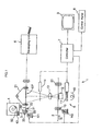
- a photographic printing apparatus 1 includes a projection exposure unit 5 for projecting and exposing image information of a film 2 on to a print paper 3 as a photosensitive material, a developing unit 6 for developing the print paper 3 exposed by the projection exposure unit 5, and a controller 7 for controlling operations of the various components of this photographic printing apparatus 1.
- the controller 7 is connected to a control panel 8 for effecting inputs of various instructions and mode settings and a monitor 9 for displaying image information.
- the projection exposure unit 5 includes a light source 10, a light modulating filter 11 for adjusting color balance of the light to be irradiated on the film 2, a mirror tunnel 12 for uniformly mixing the color components of the light past the light modulating filter 11, a printing lens 13 for focusing the image of the film 2 on the print paper 3 and a shutter 14, with these mentioned components being aligned along a common optical axis.
- roller pair or roller 19 is disposed upstream in the transport passage of the film 2, and a further roller 20 is disposed downstream.
- These rollers 19, 20 are driven by a common motor M2 in association with each other.
- a transportation of the print paper 3 in the direction from the print-paper magazine 4 to the developing unit 6 will be referred to as a forward transportation; whereas, the transportation of the paper 3 in the opposite direction from the developing unit 6 to the print-paper magazine 4 will be referred to as a reverse transportation.
- a transport belt 21 for transporting the print paper 3 in the area about this exposure position EP.
- a main drive roller mechanism 30 is disposed upstream of this transport belt 21 in the forward transportation direction.
- This main drive roller mechanism 30 includes a cylindrical member 31 contactable with the print paper 3 and a drive shaft 32 fixed coaxially with this cylindrical member 31.
- the drive shaft 32 receives a rotary drive force from a motor M1.
- the main drive roller mechanism 30 further includes two guide rollers 33 in opposition to the cylindrical member 31 across the print paper transport passage. In operation, the main drive roller mechanism 30 bi-directionally transports the print paper 3 in the forward and reversely with the paper 3 being pinched between the cylindrical member 31 and the guide rollers 33. Further, between the transport belt 21 and the main drive roller mechanism 30, there is disposed a cutter 23 for cutting the print paper 3 into a size bearing one frame amount of image information.
- the print-paper magazine 4 is attachable and detachable relative to the main body of the photographic printing apparatus 1.
- the magazine is covered with a light-shielding cover 24, inadvertent exposure of the print paper 3 withdrawn from the magazine 4 is prevented.
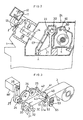
- the print-paper magazine 4 includes therein a forward drive roller mechanism 40 for feeding the print paper 3 from the magazine 4 and a reverse drive roller mechanism 50 for reversely transporting the print paper 3 back into the magazine 4, with the two mechanisms 40, 50 being disposed in opposition to each other across the print paper transport passage.
- the forward drive roller mechanism 40 and the reverse drive roller mechanism 50 are disposed upstream of the main drive roller mechanism 30 relative to the forward transportation direction.
- the forward drive roller mechanism 40 includes a first cylindrical member 41 and a first drive shaft 42 coaxial with this first cylindrical member 41.
- the reverse drive roller mechanism 50 includes a second cylindrical member 51 and a second drive shaft 52 coaxial with the second cylindrical member 51.
- the afore-mentioned motor M1 supplies a rotary drive force to the first drive shaft 42 also. And, this rotary drive force is further transmitted from this first drive shaft 42 to the second drive shaft 52 through a first intermediate gear 54 and a second intermediate gear 55.
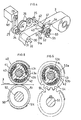
- the forward drive roller mechanism 40 includes a first roller type one-way clutch mechanism 43, as a reverse drive restricting means, interposed between the first cylindrical member 41 and the first drive shaft 42.
- This first one-way clutch mechanism 43 allows transmission of forward drive force of the motor M1 for the forward transportation from the first drive shaft 42 to the first cylindrical member 41, while inhibiting transmission of reverse drive force of the motor M1 for the reverse transportation from the first drive shaft 42 to the first cylindrical member 41.
- the reverse drive roller mechanism 50 includes a second roller type one-way clutch mechanism 53, as a forward drive restricting means, interposed between the second cylindrical member 51 and the first drive shaft 42.
- This second one-way clutch mechanism 53 allows transmission of forward drive force of the motor M1 for the reverse transportation from the first drive shaft 42 to the first intermediate gear 54 and eventually to the second cylindrical member 51, while inhibiting transmission of reverse drive force of the motor M1 for the forward transportation from the first drive shaft 42 to the first intermediate gear 54 and eventually to the second cylindrical member 51.
- the first one-way clutch mechanism 43 includes an outer race 43a fixed to the first cylindrical member 41, an inner race 43b fixed to the first drive shaft 42, and a clutch roller set 43c interposed between the outer race 43a and the inner race 43b.
- the second one-way clutch mechanism 53 includes an outer face 53a fixed to the first intermediate gear 54, an inner race 53b fixed to the first drive shaft 42, and a clutch roller set 53c interposed between the outer race 53a and the inner race 53b.
- the first cylindrical member 41 of the forward drive roller mechanism 40 and the second cylindrical member 51 of the reverse drive roller mechanism 50 are disposed in opposition to each other across the print paper 3 transported along the print paper transporting passage.
- the first cylindrical member 41 acts substantially as a drive roller while the second cylindrical member 51 acts as a guide roller.
- the second cylindrical member 51 acts substantially as a drive roller while the first cylindrical member 41 acts as a guide roller, respectively.
- a gear 24 fixed to the drive shaft 32 of the main drive roller mechanism 30 and a driven gear 25 fixed to the drive shaft 42 of the forward drive roller mechanism 40 are coupled with each other via two connecting gears 26.
- the force transmission between an output shaft of the motor M1 and the drive shaft 32 is effected by means of a timing belt transmission mechanism 27 in this particular embodiment.
- the main drive roller mechanism 30 provides a transporting speed for the print paper 3, which speed actually comprises a peripheral speed V1 of the cylindrical member 31.
- the forward drive roller mechanism 40 provides a transporting speed for the print paper 3, which speed actually comprises a peripheral speed V2 of the cylindrical member 41.
- the reverse drive roller mechanism 50 provides a transporting speed for the print paper 3, which speed actually comprises a peripheral speed V3 of the cylindrical member 51. Then, these speeds V1, V2 and V3 are determined by a transmission ratio between each cylindrical member and the motor M1 and also the diameter of each cylindrical member.
- these speeds are so correlated to each other that the peripheral speed V3 of the second cylindrical member 51 is slightly greater than the peripheral speed V1 of the cylindrical member 31 and also that the peripheral speed V1 of the cylindrical member 31 is slightly greater than the peripheral speed V2 of the first cylindrical member 41.
- the pinching force applied by the main drive roller mechanism 30 to the print paper 3 is set in advance to be stronger than the pinching force applied by the forward drive roller mechanism 40 or the reverse drive roller mechanism 50 to the print paper 3. Accordingly, when the print paper 3 is transported simultaneously by the main drive roller mechanism 30 and the forward drive roller mechanism 40 or the reverse drive roller mechanism 50, the print paper 3 is transported at the transporting speed provided by the main drive roller mechanism 30. Thus, the position of the print paper 3 can be accurately calculated from the operation of the main drive roller mechanism 30.
- the two connecting gears 26 are supported to the main body of the photographic printing apparatus 1, such that these connecting gears 26 may be disconnected from the driven gear 25 when the print-paper magazine 4 is to be detached from the photographic printing apparatus body 1.
- the developing unit 6 includes a plurality of tanks containing processing liquids for developing the exposed print paper 3.
- the print paper 3 is developed through its passages through these tanks one after another.
- the second cylindrical member 51 of the reverse drive roller mechanism 50 is also rotated in association with the movement of the print paper 3 being fed, since the rotation rate of first drive shaft 42 is higher than the rotation rate of the first intermediate gear 54 due to the afore-described relationship: V3>V1>V2; then, the first one-way clutch mechanism 53 functions to render freely rotatable the first intermediate gear 54, resultantly the second cylindrical member 51.
- the exposure condition used in the above step is determined in advance based on image density information derived from the image information of the film 2 picked up by an un-illustrated image information pick-up device under the control of the controller 7. And, the light modulating filter 11 and the shutter 14 are controlled to as to provide this determined exposure condition.
- the print paper 3 after its exposure is then developed by the developing unit 6 and discharged from the system.
- the peripheral speed of the second cylindrical member 51 of the reverse drive roller mechanism 50 is faster than the current transporting speed of the print paper 3, slippage occurs between the second cylindrical member 51 and this print paper 3.
- the second cylindrical member 51 defines, in its surface, a limited-slip friction surface 51a as means for decreasing the transporting drive force.
- the rotation rate of the first cylindrical member 41 of the forward drive roller mechanism 40 driven to rotate by the movement of the print paper 3 tends to become higher than the rotation rate of the drive shaft 42 due to the relationship: V3>V1>V2. Then, the first one-way clutch mechanism 43 is activated to match the rotation rate of the first cylindrical member 41 with that of the drive shaft 42.
Landscapes
- Physics & Mathematics (AREA)
- General Physics & Mathematics (AREA)
- Projection-Type Copiers In General (AREA)
- Photographic Developing Apparatuses (AREA)
Description
Claims (8)
- A transporting apparatus for a photographic processing apparatus, the processing apparatus having a photosensitive material magazine (4) and processing a photosensitive material (3) transported from the photosensitive material magazine (4), the transporting apparatus transporting the photosensitive material from the photosensitive material magazine (4) in forward and reverse directions, the transporting apparatus comprising:a main pinch transport mechanism (30) which is driven rotatably to transport the photosensitive material (3) in the forward and reverse directions;first and second auxiliary pinch transport mechanisms (40, 50) disposed upstream of the main pinch transport mechanism (3) relative to the forward transport direction, the first and second auxiliary pinch transport mechanisms being supplied with a rotational force by a common drive source (M1) and disposed in opposition to each other so as to pinch the photosensitive material therebetween;reverse drive restricting means (43) provided to the first auxiliary pinch transport mechanism (40) for restricting transmission of the rotational force supplied from the common drive source (M1) to a portion of the first auxiliary pinch transport mechanism (4) contacting the photosensitive material (3), when the photosensitivematerial (3) is transported in the reverse direction; andforward drive restricting means (53) provided to thesecond auxiliary pinch transport mechanism (50) forrestricting the rotational force supplied from the commondrive source (M1) to the second auxiliary pinch transport mechanism (50) when the photosensitive material (3) is transported in the forward direction.
- A transporting apparatus as defined in claim 1
characterized in that, it comprises the photsensitive material magazine (4) and the first and second auxiliary pinch transport mechanisms (40, 50) are located in the photosensitive material magazine (4). - A transporting apparatus as defined in claim 1,
characterized in that,
the main pinch transport mechanism (30) is supplied with the rotational force from the common drive source (Ml). - A transporting apparatus as defined in claim 1,
characterized in that
the first auxiliary pinch transport mechanism comprises a forward rotary drive roller mechanism (40) which can come into contact with a first drive shaft (42) and the photosensitive material and which includes a first cylindrical member (41) rotatable by the first drive shaft, the reverse drive restricting means (43) being disposed in a force transmission passage between the drive source and the first cylindrical member; and
the second auxiliary pinch transport mechanism comprises a reverse rotary drive roller mechanism (50) which can come into contact-with a second drive shaft (52) and the photosensitive material and which includes a second cylindrical member (51) rotatable by the second drive shaft, the forward drive restricting means (53) being disposed in a force transmission passage between the drive source and the second cylindrical member. - A transporting apparatus as defined in claim 3,
characterized in that
the main pinch transport mechanism comprises a main drive roller mechanism (30) having a cylindrical member which can come into contact with the photosensitive material, said cylindrical member (31) of the main drive roller mechanism having a peripheral speed which is faster than a peripheral speed of the first cylindrical member (41). - A transporting apparatus as defined in claim 6,
characterized in that
said reverse drive restricting means comprises a one-way clutch mechanism (43) for allowing the force transmission from the first drive shaft (42) to the first cylindrical member (41) only when the photosensitive material is transported the forward transportation direction; and
said forward drive restricting means comprises a one-way clutch mechanism (53) for allowing the force transmission from the second drive shaft (52) to the second cylindrical member (51) only when the photosensitive material is transported in the reverse transporting direction. - A transporting apparatus as defined in claim 5,
characterized in that
the second cylindrical member (51) has a peripheral speed which is faster than the peripheral speed of the cylindrical member (31) of the main drive roller mechanism (30), drive force decreasing means (51a) being provided for allowing slippage of the photosensitive material relative to the second cylindrical member (51) during the reverse transportation of the photosensitive material. - A transporting apparatus as defined in claim 8,
characterized in that
said drive force decreasing means comprises a limited-slip friction surface (51a) formed in the surface of the second cylindrical member (51).
Applications Claiming Priority (3)
| Application Number | Priority Date | Filing Date | Title |
|---|---|---|---|
| JP574995 | 1995-01-18 | ||
| JP5749/95 | 1995-01-18 | ||
| JP574995 | 1995-01-18 |
Publications (2)
| Publication Number | Publication Date |
|---|---|
| EP0723182A1 EP0723182A1 (en) | 1996-07-24 |
| EP0723182B1 true EP0723182B1 (en) | 2003-07-30 |
Family
ID=11619767
Family Applications (1)
| Application Number | Title | Priority Date | Filing Date |
|---|---|---|---|
| EP19960100534 Expired - Lifetime EP0723182B1 (en) | 1995-01-18 | 1996-01-16 | Transporting apparatus |
Country Status (2)
| Country | Link |
|---|---|
| EP (1) | EP0723182B1 (en) |
| DE (1) | DE69629223T2 (en) |
Families Citing this family (1)
| Publication number | Priority date | Publication date | Assignee | Title |
|---|---|---|---|---|
| JPH11231439A (en) | 1998-02-17 | 1999-08-27 | Noritsu Koki Co Ltd | Photographic paper exposure method and optical digital printer using the method |
Family Cites Families (4)
| Publication number | Priority date | Publication date | Assignee | Title |
|---|---|---|---|---|
| JPS59111134A (en) * | 1982-12-16 | 1984-06-27 | Fuji Photo Film Co Ltd | Photosensitive material storage magazine |
| JPS63202484A (en) * | 1987-02-18 | 1988-08-22 | Matsushita Electric Ind Co Ltd | Printer |
| JPS63283270A (en) * | 1987-05-15 | 1988-11-21 | Ricoh Co Ltd | Roller driving mechanism for facsimile equipment |
| JPH06156832A (en) * | 1992-07-06 | 1994-06-03 | Murata Mach Ltd | Paper feeding device |
-
1996
- 1996-01-16 EP EP19960100534 patent/EP0723182B1/en not_active Expired - Lifetime
- 1996-01-16 DE DE1996629223 patent/DE69629223T2/en not_active Expired - Lifetime
Also Published As
| Publication number | Publication date |
|---|---|
| DE69629223D1 (en) | 2003-09-04 |
| DE69629223T2 (en) | 2004-04-22 |
| EP0723182A1 (en) | 1996-07-24 |
Similar Documents
| Publication | Publication Date | Title |
|---|---|---|
| JP2889736B2 (en) | Paper transport device for photo printer | |
| JP3454348B2 (en) | Conveyor for photosensitive material | |
| CA2167435C (en) | Photographic processing apparatus | |
| EP0622664B1 (en) | Apparatus for supplying photosensitive material | |
| US5393044A (en) | Paper feeder | |
| EP0723182A1 (en) | Photographic processing apparatus | |
| JP4110334B2 (en) | Gear-type power transmission device in image forming apparatus | |
| JP3207504B2 (en) | Sheet transport device | |
| JP3458933B2 (en) | Guide width adjustment method and adjustment device for photographic photosensitive material | |
| KR100217408B1 (en) | Photographic processing apparatus | |
| JP3698299B2 (en) | Photosensitive material transport mechanism | |
| JP2861727B2 (en) | Photosensitive material supply device | |
| JPH0270647A (en) | Media sheet conveyer | |
| JP2942676B2 (en) | Transfer control device for photo printing equipment | |
| JPH04359236A (en) | Film projecting device | |
| JP2002370846A (en) | Sheet feeding / conveying apparatus and image forming apparatus provided with the apparatus | |
| JP2572455B2 (en) | Image shift prevention method | |
| JP2002182317A (en) | Photosensitive material guide device for magazine | |
| KR100194369B1 (en) | Paper Magazine | |
| JP3287736B2 (en) | Photographing device and image recording device | |
| JPH06138556A (en) | Carrier controller for photographic printer | |
| JPH10120231A (en) | Driving device for automatic document conveying device | |
| JPH06138557A (en) | Carrier controller for photograph printer | |
| JP2000056404A (en) | Film transport unit and film processing method | |
| JPH0511356A (en) | Carrying mechanism in printer part for photosensitive material |
Legal Events
| Date | Code | Title | Description |
|---|---|---|---|
| PUAI | Public reference made under article 153(3) epc to a published international application that has entered the european phase |
Free format text: ORIGINAL CODE: 0009012 |
|
| AK | Designated contracting states |
Kind code of ref document: A1 Designated state(s): CH DE FR GB IT LI |
|
| 17P | Request for examination filed |
Effective date: 19960725 |
|
| 17Q | First examination report despatched |
Effective date: 19991130 |
|
| RTI1 | Title (correction) |
Free format text: TRANSPORTING APPARATUS |
|
| GRAH | Despatch of communication of intention to grant a patent |
Free format text: ORIGINAL CODE: EPIDOS IGRA |
|
| GRAH | Despatch of communication of intention to grant a patent |
Free format text: ORIGINAL CODE: EPIDOS IGRA |
|
| GRAA | (expected) grant |
Free format text: ORIGINAL CODE: 0009210 |
|
| AK | Designated contracting states |
Designated state(s): CH DE FR GB IT LI |
|
| PG25 | Lapsed in a contracting state [announced via postgrant information from national office to epo] |
Ref country code: LI Free format text: LAPSE BECAUSE OF FAILURE TO SUBMIT A TRANSLATION OF THE DESCRIPTION OR TO PAY THE FEE WITHIN THE PRESCRIBED TIME-LIMIT Effective date: 20030730 Ref country code: IT Free format text: LAPSE BECAUSE OF FAILURE TO SUBMIT A TRANSLATION OF THE DESCRIPTION OR TO PAY THE FEE WITHIN THE PRE;WARNING: LAPSES OF ITALIAN PATENTS WITH EFFECTIVE DATE BEFORE 2007 MAY HAVE OCCURRED AT ANY TIME BEFORE 2007. THE CORRECT EFFECTIVE DATE MAY BE DIFFERENT FROM THE ONE RECORDED.SCRIBED TIME-LIMIT Effective date: 20030730 Ref country code: CH Free format text: LAPSE BECAUSE OF FAILURE TO SUBMIT A TRANSLATION OF THE DESCRIPTION OR TO PAY THE FEE WITHIN THE PRESCRIBED TIME-LIMIT Effective date: 20030730 |
|
| REG | Reference to a national code |
Ref country code: GB Ref legal event code: FG4D |
|
| REG | Reference to a national code |
Ref country code: CH Ref legal event code: EP |
|
| REF | Corresponds to: |
Ref document number: 69629223 Country of ref document: DE Date of ref document: 20030904 Kind code of ref document: P |
|
| REG | Reference to a national code |
Ref country code: CH Ref legal event code: PL |
|
| ET | Fr: translation filed | ||
| PLBE | No opposition filed within time limit |
Free format text: ORIGINAL CODE: 0009261 |
|
| STAA | Information on the status of an ep patent application or granted ep patent |
Free format text: STATUS: NO OPPOSITION FILED WITHIN TIME LIMIT |
|
| 26N | No opposition filed |
Effective date: 20040504 |
|
| PGFP | Annual fee paid to national office [announced via postgrant information from national office to epo] |
Ref country code: FR Payment date: 20050110 Year of fee payment: 10 |
|
| PGFP | Annual fee paid to national office [announced via postgrant information from national office to epo] |
Ref country code: GB Payment date: 20050112 Year of fee payment: 10 |
|
| PG25 | Lapsed in a contracting state [announced via postgrant information from national office to epo] |
Ref country code: GB Free format text: LAPSE BECAUSE OF NON-PAYMENT OF DUE FEES Effective date: 20060116 |
|
| PG25 | Lapsed in a contracting state [announced via postgrant information from national office to epo] |
Ref country code: FR Free format text: LAPSE BECAUSE OF NON-PAYMENT OF DUE FEES Effective date: 20060131 |
|
| GBPC | Gb: european patent ceased through non-payment of renewal fee |
Effective date: 20060116 |
|
| REG | Reference to a national code |
Ref country code: FR Ref legal event code: ST Effective date: 20060929 |
|
| PGFP | Annual fee paid to national office [announced via postgrant information from national office to epo] |
Ref country code: DE Payment date: 20100114 Year of fee payment: 15 |
|
| REG | Reference to a national code |
Ref country code: DE Ref legal event code: R119 Ref document number: 69629223 Country of ref document: DE Effective date: 20110802 |
|
| PG25 | Lapsed in a contracting state [announced via postgrant information from national office to epo] |
Ref country code: DE Free format text: LAPSE BECAUSE OF NON-PAYMENT OF DUE FEES Effective date: 20110802 |