EP0722426B1 - Fluid diffuser - Google Patents
Fluid diffuser Download PDFInfo
- Publication number
- EP0722426B1 EP0722426B1 EP94928947A EP94928947A EP0722426B1 EP 0722426 B1 EP0722426 B1 EP 0722426B1 EP 94928947 A EP94928947 A EP 94928947A EP 94928947 A EP94928947 A EP 94928947A EP 0722426 B1 EP0722426 B1 EP 0722426B1
- Authority
- EP
- European Patent Office
- Prior art keywords
- layer
- fluid
- diffuser
- restraining
- pores
- Prior art date
- Legal status (The legal status is an assumption and is not a legal conclusion. Google has not performed a legal analysis and makes no representation as to the accuracy of the status listed.)
- Expired - Lifetime
Links
- 239000012530 fluid Substances 0.000 title claims abstract description 47
- 239000000463 material Substances 0.000 claims abstract description 67
- 239000011148 porous material Substances 0.000 claims abstract description 31
- 238000000034 method Methods 0.000 claims abstract description 14
- 230000000452 restraining effect Effects 0.000 claims description 37
- 229920002994 synthetic fiber Polymers 0.000 claims description 4
- 239000002759 woven fabric Substances 0.000 abstract description 24
- 230000008569 process Effects 0.000 abstract description 9
- XLYOFNOQVPJJNP-UHFFFAOYSA-N water Substances O XLYOFNOQVPJJNP-UHFFFAOYSA-N 0.000 abstract description 4
- 229920000642 polymer Polymers 0.000 description 20
- 239000002131 composite material Substances 0.000 description 16
- 229920006254 polymer film Polymers 0.000 description 11
- 239000004744 fabric Substances 0.000 description 9
- 238000007789 sealing Methods 0.000 description 9
- 230000010339 dilation Effects 0.000 description 6
- 230000000694 effects Effects 0.000 description 5
- 230000009471 action Effects 0.000 description 4
- 239000000919 ceramic Substances 0.000 description 4
- 239000010865 sewage Substances 0.000 description 4
- 230000001360 synchronised effect Effects 0.000 description 4
- QVGXLLKOCUKJST-UHFFFAOYSA-N atomic oxygen Chemical compound [O] QVGXLLKOCUKJST-UHFFFAOYSA-N 0.000 description 3
- 230000001351 cycling effect Effects 0.000 description 3
- 239000005038 ethylene vinyl acetate Substances 0.000 description 3
- 239000001301 oxygen Substances 0.000 description 3
- 229910052760 oxygen Inorganic materials 0.000 description 3
- 229920001200 poly(ethylene-vinyl acetate) Polymers 0.000 description 3
- 229920000915 polyvinyl chloride Polymers 0.000 description 3
- 239000004800 polyvinyl chloride Substances 0.000 description 3
- 229920002379 silicone rubber Polymers 0.000 description 3
- 239000004677 Nylon Substances 0.000 description 2
- 229910000831 Steel Inorganic materials 0.000 description 2
- 230000008901 benefit Effects 0.000 description 2
- 230000015572 biosynthetic process Effects 0.000 description 2
- 239000007788 liquid Substances 0.000 description 2
- 238000004519 manufacturing process Methods 0.000 description 2
- 239000002184 metal Substances 0.000 description 2
- 229920001778 nylon Polymers 0.000 description 2
- -1 polyethylene Polymers 0.000 description 2
- 229920003225 polyurethane elastomer Polymers 0.000 description 2
- 230000001020 rhythmical effect Effects 0.000 description 2
- 239000004945 silicone rubber Substances 0.000 description 2
- 239000010959 steel Substances 0.000 description 2
- 239000004698 Polyethylene Substances 0.000 description 1
- 239000004743 Polypropylene Substances 0.000 description 1
- 238000005299 abrasion Methods 0.000 description 1
- 238000005273 aeration Methods 0.000 description 1
- 241001148470 aerobic bacillus Species 0.000 description 1
- DQXBYHZEEUGOBF-UHFFFAOYSA-N but-3-enoic acid;ethene Chemical compound C=C.OC(=O)CC=C DQXBYHZEEUGOBF-UHFFFAOYSA-N 0.000 description 1
- 238000003490 calendering Methods 0.000 description 1
- 230000003247 decreasing effect Effects 0.000 description 1
- 230000000916 dilatatory effect Effects 0.000 description 1
- 238000001125 extrusion Methods 0.000 description 1
- 230000009969 flowable effect Effects 0.000 description 1
- 230000004907 flux Effects 0.000 description 1
- 239000007789 gas Substances 0.000 description 1
- 229920001684 low density polyethylene Polymers 0.000 description 1
- 239000004702 low-density polyethylene Substances 0.000 description 1
- 229920001179 medium density polyethylene Polymers 0.000 description 1
- 239000004701 medium-density polyethylene Substances 0.000 description 1
- 239000005416 organic matter Substances 0.000 description 1
- 239000002245 particle Substances 0.000 description 1
- 230000002572 peristaltic effect Effects 0.000 description 1
- 229920003023 plastic Polymers 0.000 description 1
- 239000004033 plastic Substances 0.000 description 1
- 229920000573 polyethylene Polymers 0.000 description 1
- 229920005597 polymer membrane Polymers 0.000 description 1
- 229920000307 polymer substrate Polymers 0.000 description 1
- 229920001155 polypropylene Polymers 0.000 description 1
- 229920002635 polyurethane Polymers 0.000 description 1
- 239000004814 polyurethane Substances 0.000 description 1
- 230000002441 reversible effect Effects 0.000 description 1
Images



Classifications
-
- B—PERFORMING OPERATIONS; TRANSPORTING
- B01—PHYSICAL OR CHEMICAL PROCESSES OR APPARATUS IN GENERAL
- B01F—MIXING, e.g. DISSOLVING, EMULSIFYING OR DISPERSING
- B01F23/00—Mixing according to the phases to be mixed, e.g. dispersing or emulsifying
- B01F23/20—Mixing gases with liquids
- B01F23/23—Mixing gases with liquids by introducing gases into liquid media, e.g. for producing aerated liquids
- B01F23/231—Mixing gases with liquids by introducing gases into liquid media, e.g. for producing aerated liquids by bubbling
- B01F23/23105—Arrangement or manipulation of the gas bubbling devices
- B01F23/2312—Diffusers
- B01F23/23122—Diffusers having elements opening under air pressure, e.g. valves
-
- B—PERFORMING OPERATIONS; TRANSPORTING
- B26—HAND CUTTING TOOLS; CUTTING; SEVERING
- B26F—PERFORATING; PUNCHING; CUTTING-OUT; STAMPING-OUT; SEVERING BY MEANS OTHER THAN CUTTING
- B26F1/00—Perforating; Punching; Cutting-out; Stamping-out; Apparatus therefor
- B26F1/0015—Perforating; Punching; Cutting-out; Stamping-out; Apparatus therefor specially adapted for perforating tubes
-
- B—PERFORMING OPERATIONS; TRANSPORTING
- B01—PHYSICAL OR CHEMICAL PROCESSES OR APPARATUS IN GENERAL
- B01F—MIXING, e.g. DISSOLVING, EMULSIFYING OR DISPERSING
- B01F23/00—Mixing according to the phases to be mixed, e.g. dispersing or emulsifying
- B01F23/20—Mixing gases with liquids
- B01F23/23—Mixing gases with liquids by introducing gases into liquid media, e.g. for producing aerated liquids
- B01F23/231—Mixing gases with liquids by introducing gases into liquid media, e.g. for producing aerated liquids by bubbling
- B01F23/23105—Arrangement or manipulation of the gas bubbling devices
- B01F23/2312—Diffusers
- B01F23/23124—Diffusers consisting of flexible porous or perforated material, e.g. fabric
-
- B—PERFORMING OPERATIONS; TRANSPORTING
- B01—PHYSICAL OR CHEMICAL PROCESSES OR APPARATUS IN GENERAL
- B01F—MIXING, e.g. DISSOLVING, EMULSIFYING OR DISPERSING
- B01F23/00—Mixing according to the phases to be mixed, e.g. dispersing or emulsifying
- B01F23/20—Mixing gases with liquids
- B01F23/23—Mixing gases with liquids by introducing gases into liquid media, e.g. for producing aerated liquids
- B01F23/231—Mixing gases with liquids by introducing gases into liquid media, e.g. for producing aerated liquids by bubbling
- B01F23/23105—Arrangement or manipulation of the gas bubbling devices
- B01F23/2312—Diffusers
- B01F23/23124—Diffusers consisting of flexible porous or perforated material, e.g. fabric
- B01F23/231241—Diffusers consisting of flexible porous or perforated material, e.g. fabric the outlets being in the form of perforations
-
- B—PERFORMING OPERATIONS; TRANSPORTING
- B01—PHYSICAL OR CHEMICAL PROCESSES OR APPARATUS IN GENERAL
- B01F—MIXING, e.g. DISSOLVING, EMULSIFYING OR DISPERSING
- B01F35/00—Accessories for mixers; Auxiliary operations or auxiliary devices; Parts or details of general application
- B01F35/10—Maintenance of mixers
-
- C—CHEMISTRY; METALLURGY
- C02—TREATMENT OF WATER, WASTE WATER, SEWAGE, OR SLUDGE
- C02F—TREATMENT OF WATER, WASTE WATER, SEWAGE, OR SLUDGE
- C02F3/00—Biological treatment of water, waste water, or sewage
- C02F3/02—Aerobic processes
- C02F3/12—Activated sludge processes
- C02F3/20—Activated sludge processes using diffusers
- C02F3/201—Perforated, resilient plastic diffusers, e.g. membranes, sheets, foils, tubes, hoses
-
- B—PERFORMING OPERATIONS; TRANSPORTING
- B01—PHYSICAL OR CHEMICAL PROCESSES OR APPARATUS IN GENERAL
- B01F—MIXING, e.g. DISSOLVING, EMULSIFYING OR DISPERSING
- B01F23/00—Mixing according to the phases to be mixed, e.g. dispersing or emulsifying
- B01F23/20—Mixing gases with liquids
- B01F23/23—Mixing gases with liquids by introducing gases into liquid media, e.g. for producing aerated liquids
- B01F23/231—Mixing gases with liquids by introducing gases into liquid media, e.g. for producing aerated liquids by bubbling
- B01F23/23105—Arrangement or manipulation of the gas bubbling devices
- B01F23/2312—Diffusers
- B01F23/23126—Diffusers characterised by the shape of the diffuser element
- B01F23/231265—Diffusers characterised by the shape of the diffuser element being tubes, tubular elements, cylindrical elements or set of tubes
-
- Y—GENERAL TAGGING OF NEW TECHNOLOGICAL DEVELOPMENTS; GENERAL TAGGING OF CROSS-SECTIONAL TECHNOLOGIES SPANNING OVER SEVERAL SECTIONS OF THE IPC; TECHNICAL SUBJECTS COVERED BY FORMER USPC CROSS-REFERENCE ART COLLECTIONS [XRACs] AND DIGESTS
- Y02—TECHNOLOGIES OR APPLICATIONS FOR MITIGATION OR ADAPTATION AGAINST CLIMATE CHANGE
- Y02W—CLIMATE CHANGE MITIGATION TECHNOLOGIES RELATED TO WASTEWATER TREATMENT OR WASTE MANAGEMENT
- Y02W10/00—Technologies for wastewater treatment
- Y02W10/10—Biological treatment of water, waste water, or sewage
Definitions
- This invention relates to a fluid diffuser, for diffusing a first fluid into a second fluid, for example for delivering air or another liquid or gaseous fluid in finely divided form to a surrounding medium.
- a common use of a fluid diffuser is in the aeration of polluted mediums, for example sewage or polluted lakes or waterways.
- polluted mediums for example sewage or polluted lakes or waterways.
- air bubbles are passed through the diffuser into a medium to be treated. Oxygen in the air bubbles then dissolves in the medium, whereupon it is taken up by aerobic bacteria that digest polluting organic matter and thereby clarify the medium.
- the air bubble size should not exceed 1mm in diameter and should preferably be of the order of 50 to 100 ⁇ m in diameter.
- Such air bubbles can be generated using very fine ceramic diffusers, for example in the form of ceramic tubes having a nominal pore size of 3 to 10 ⁇ m.
- ceramic tubes are brittle, expensive, can only be produced in short lengths and require a high internal air pressure to function.
- the pores of the tubes remain permanently open and will allow back leakage of effluent, if the internal air pressure is removed.
- a fluid diffuser which comprises an elongate flexible member having opposed walls defining a fluid delivery tube.
- the walls include a multiplicity of minutes valves formed by non-ablative perforation of the material of the flexible member.
- the valves are arranged to seal tight (and thereby prevent back-leakage of effluent), when the air pressure within the tube is below a threshold pressure. At the threshold pressure, the valves are arranged to emit tiny air bubbles into the medium surrounding the tube.
- the material of the walls of the tube of the aforementioned fluid diffuser must have some resilience so that the valves can be self-sealing. This may lead to a problem in that, as air pressure within the tube increases, the tube expands radially outwardly and valve dilation increases. The increased valve dilation leads to the emission of larger air bubbles which are less efficient at oxygen transfer than small bubbles.
- DE-U-87 14 502 discloses a device according to the pre-characterising part of Claim 1.
- a device for diffusing a first fluid into a second fluid comprising a tubular member which includes pores for passage of fluid from inside the tubular member to the outside, said pores being arranged to be self-closing when a fluid is not flowing therethrough, said member including a restraining layer and an inner layer arranged inwardly of said restraining layer, characterised in that said member includes an outer layer arranged outwardly of said restraining layer and said retraining layer co-operates with said inner layer and said outer layer for restraining an increase in pore size as the pressure of fluid flowing to the outside through the pores of said member is increased.
- the term "diffuser” includes any device for passing a first fluid into a second fluid.
- the device is used for diffusing air into a liquid
- increasing the air pressure within the device may advantageously not affect, to any significant degree, the pore size or the emitted air bubble size.
- the device may function in a manner similar to ceramic diffusers whilst obviating problems associated therewith.
- the restraining means is preferably arranged so as to restrain lateral expansion of the pores of the tubular member.
- an area of the inner layer around each pore defined therein is covered by said restraining layer.
- said restraining layer covers substantially the entirety of said inner Iayer.
- each of a multiplicity of said pores is restrained by a respective part of said restraining layer.
- each of a multiplicity of said pores is individually restrained by said restraining layer.
- each of said multiplicity of pores is restrained to substantially the same extent; that is, said restraining layer is preferably arranged to exert a restraining force of substantially the same magnitude on each pore.
- Said restraining layer suitably includes means arranged to define openings which openings are arranged to co-operate in use with pores in said inner and outer layers for allowing the flow of fluid through said tubular member.
- the openings in said restraining layer are arranged to be aligned with pores in said inner and outer layers.
- the openings and pores may be non-aligned.
- walls which define said openings of said restraining layer may be arranged circumferentially around the pores for restraining lateral expansion of the pores beyond a predetermined limited.
- Said inner layer and said restraining layer are preferably in intimate contact.
- Said inner layer and said restraining layer may be bonded to one another.
- Said inner layer and said restraining layer may be bonded together by the action of heat.
- the material of said inner layer is preferably resilient and/or substantially incompressible and/or flowable and/or flexible and/or a synthetic material and/or not negatively buoyant and/or a polymeric material.
- Preferred materials include heat-sealable synthetic plastics materials, for example polyvinyl chloride, polyethylene and ethylene vinyl acetate and bondable materials such as silicone rubbers and polyurethane rubbers.
- the material of said restraining layer is preferably relatively inelastic and/or flexible and/or a synthetic material and/or a polymeric material and/or not negatively buoyant.
- the material of said restraining layer may be one of the preferred materials described for the inner layer.
- said restraining layer includes parts which extend in a first direction and parts which extend in a second direction, said first and second directions preferably being perpendicular.
- said parts are comprised by warp and weft strands of a woven fabric material.
- the material of said restraining layer is a woven fabric material.
- openings defined between warp and weft strands of the fabric material are preferably aligned with pores defined in said inner layer.
- parts of the inner layer are disposed between the openings defined between said warp and weft strands.
- material of said inner layer may flow into openings defined between said warp and weft strands during the process of bonding the inner layer and restraining layer to one another.
- a negative buoyancy aid may be associated with said device.
- Said negative buoyancy aid may be held captive by opposed walls of the device in spaced relationship with said tubular member. Alternatively and/or additionally, said negative buoyancy aid may be suspended beneath the tubular member.
- said tubular member is arranged to have a circular cross-section when a fluid is flowing therein.
- the tubular member may be arranged to collapse, suitably into a substantially flat state, when a fluid is not flowing therein.
- the device may include buoyancy adjustment means for altering the buoyancy thereof.
- Said buoyancy adjustment means may be provided if it may be desirable to vary the submerged depth of the device.
- Said buoyancy adjustment means may comprise a further, unperforated tube which is inflatable to a variable extent so as to alter the buoyancy of the device.
- a buoyancy adjustment means as described may be particularly useful in the case of a submergible boom as described in U.K. Patent Application No. 9116072 (relating to a submergible boom for controlling oil spillages) because the boom may be positioned at any required depth depending upon the weather conditions or it may be positioned at a suitable depth below an oil spillage.
- said tubular member may comprise at least two extruded, suitably circular cross-section and seamless, tubes, one being arranged within the other.
- a woven fabric material of the type described above may be arranged between said tubes.
- the device of the first aspect preferably further includes tethering means for tethering the device in position in use.
- the negative buoyancy aid is in the form of a metal filament
- said metal filament may extend beyond the ends of the tubular member and be equipped with end fittings for tethering the device in a position of use.
- the device preferably includes means for removably securing a fluid delivery line.
- the device described above is suitably at least 0.5 metres in length.
- the device is at least 1 metre in length.
- the device may be greater than 5 or 10 metres in length.
- the device is preferably sufficiently flexible such that is may be stored in a rolled up state; for example, it may be stored on a reel in the manner of a hose.
- a method of diffusing a fluid into a surrounding medium for example air into sewage comprising placing a device according to the first aspect into said medium and introducing the fluid into the device at a pressure such that the fluid is forced through the pores into the surrounding medium.
- a device according to a first aspect for diffusing a fluid into a surrounding medium.
- FIGS 1 to 5 have been included for the purposes of disclosure.
- Figures 6 to 9 relate to embodiments of the present invention.
- the fluid diffuser 2 comprises an elongate material strip (of which only a short section is shown) made from two separate composite sheets 4,6 which are separately perforated in two lateral zones 8a, 8b and 10a, 10b and then heat-sealed together at their longitudinal edges 12, 14 and at intermediate positions 16, 18 to either side of a flexible steel cable 20 positioned between the sheets 4, 6.
- the perforations in zones 8a, 8b, 10a and 10b have been omitted in the interests of clarity).
- the fluid diffuser 2 thus has opposed walls formed by sheets 4, 6 incorporating fluid delivery tubes 22, 24 with perforations provided by the coinciding perforated zones 8a, 10a and 8b, 10b.
- the steel cable 20 provides a negative buoyancy aid which is trapped and sealed in position by the heat sealed portions 16, 18.
- the fluid diffuser 2 is similar to, and may be manufactured in a similar manner to, diffusers described in co-pending International application number PCT/GB 93/01196 and the contents of said International application are incorporated herein by reference.
- the fluid diffuser 2 differs from diffusers described in said International application by the provision of composite sheets 4, 6 (described in detail below) instead of plain polymer membranes described in the International application.
- Each composite sheet 4,6 is comprised of a resilient polymer film layer and a woven fabric material layer, the layers being integrally bonded to one another.
- the material of the polymer film layer may be, for example, plasticised polyvinyl chloride, low or medium density polyethylene, ethylene vinyl acetate, silicone rubber or polyurethane rubber.
- the woven fabric material may be, for example, woven nylon material.
- a composite sheet of material is formed by calendering sheets of the polymer film and woven fabric materials together at an elevated temperature. During the process, the sheets become bonded to one another in such a manner that the polymer film layer is "extruded" into mesh spaces defined between warp and weft strands of the woven fabric material, thereby forming islands of polymer film between the strands of woven fabric.
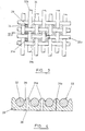
- polymer film layer 26 includes polymer islands 28 which are arranged, in the composite material 30, in spaces defined between warp (or weft) strands 32 of woven fabric material 33.
- the composite sheet of material 30 Prior to being formed into a tube, the composite sheet of material 30 is subjected to a non-ablative piercing process. Needle wheels as described in International application number PCT/GB 93/01196 may be used in the process. It has been found that piercing can be made to occur only in the polymer islands 28, leaving the warp and weft strands 32 of the fabric material 33 unaffected. It is believed that, during the piercing process, the needles of the needle wheels push aside any warp or weft strands they encounter and, therefore, only pierce the polymer islands 28. The piercing process results in the formation of extremely small self-sealing valves 31 ( Figures 3 and 4), each one being contained within its own mesh boundary, defined by weft and warp strands 32.
- Tubes 22,24 of diffuser 2 are then made by bonding pierced composite sheets 4, 6 together as described in International application number PCT/GB 93/01196.
- the tubes 22, 24 are formed such that the polymer film layer 26 defines the inside wall of the tubes and the woven fabric material layer 33 is on the outside of the tubes.
- the tubes 22, 24 function significantly differently compared to those described in PCT/GB 93/01196, due to the provision of the composite sheets 4, 6. It has been found that the woven fabric material layer 33 confers great length and lateral dimensional stability on the tubes 22, 24, so that diametral or circumferential expansion of the tubes is severely restricted. Furthermore, the polymer islands 28 are tightly bound on a miniature scale. The functioning of the tubes 22, 24 is described further below.
- the tubes When air pressure is introduced into flattened tubes 22, 24, the tubes expand until they reach a diametral limit imposed by the circumferential restraint of the strands of the woven fabric material.
- the fabric material is substantially non-expansible and, therefore, any further expansion of the tubes is severely constrained.
- the tubes are essentially diametrically stable (within operational design limits).
- diametral expansion of the tubes can play little or no part in valve dilation; i.e. increasing air pressure in the tubes does not result in valve dilation due to an increase in the diameter of the tubes.
- the only resilience within the tubes are the islands of polymer in the mesh spaces and even these are constrained by the weft and warp strands that form the mesh boundary.
- the only route for air to escape from the tubes is via the self-sealing valves in the mesh boundaries. At a threshold pressure, the valves open minutely and very small bubbles are emitted at a relatively slow rate.
- FIGS 3 and 4 illustrate the arrangement and possible- functioning of the composite material of the tubes 22, 24.
- the figures illustrate weft strands 32a and warp strands 32b which define mesh boundaries 34 within which islands 28 of the polymer film layer 26 are disposed.
- Self-sealing valves 31 are provided within the mesh boundaries 34.
- the valves 31 are arranged to open (e.g. see valves 31a) and close (e.g. see valves 31b) when subject to a fluid pressure on the polymer film side 36 of the composite material.
- the threshold pressure and nominal operating range of the self-sealing valves of the diffuser may be varied, at the design stage, to suit particular applications.
- a typical operating regime may be a threshold pressure of 1 psi (6896 Pa) and an operating range of 1-4 psi (6896 - 27586 Pa).
- a diffuser may be constructed so as to produce air bubbles of any desired size and maintain that bubble size, within very close limits, across the operating pressure range of the diffuser.
- the only effect is a dramatic increase in the bubble flux (a greater number of bubbles), of almost identically sized bubbles.
- the constrained valves of the diffuser 2 produce rather complex dynamics which are believed to be as follows.
- the valves When in operation, the valves are constantly in motion throughout their depth. Furthermore, each valve is closely adjacent to its neighbour and suitably all valves are identically stressed, at any given operating pressure.
- the individual valve action When operating, the individual valve action is cyclical; constantly and rhythmically opening and closing.
- the cycle rate is directly related to the pressure within the tubes of the diffuser. The higher the pressure, the faster the open/close/open cycle. Because of the very close proximity of the individual valves and the resilience of the polymer layer 26, the valves are believed to operate in a synchronous cycle, within closely related groups. This synchronous effect is due to the resilience of the polymer film layer 26.
- valve 31a As a valve 31a is forced open by air pressure 40 in the tube, the portion of the polymer layer 26 which defines the wall of the valve 31a is deflected as represented by arrows 42. This deflection stress is partially transmitted to neighbouring valves in the "group” (for example, valve 31b), thereby “pinching” them tighter (for example as shown at position 44).
- the resilience of the material of the polymer layer 26 causes initially open valve 31a to rebound or "snap back" against the stress and it closes down trapping a minute air pocket 46 within it. This relief of stress in the valve 31a removes the "pinch” on its near neighbour 31b and allows that valve to move through the same cycle.
- rhythmical stress reversals cause synchronous, group valve cycling.
- valves 31 operate at the same rate, ie. the same open/close/open cycle time. Increasing the pressure causes faster cycling; conversely, decreasing the pressure causes slower cycling. Because of the rebound or "snap back" of the valves 31, the minute pockets of air 46 enclosed by the valves are subject to increased pressure as they migrate along the length of the valves. In effect, the valves act like peristaltic pumps, squeezing minute air parcels 46 along their length.
- an air parcel 46 passes along the length of a valve 31, it moves out of a pure polymer substrate zone 48 of the polymer layer 26 and into a zone 50 where the polymer is surrounded and constrained by the fabric material 23, ie. into the polymer islands or upswells 28 described above.
- zone 50 circumferential or diametric expansion of the valve is severely limited, by virtue of the constraint by the weft and warp strands 32 of the fabric material 33 and, in view of this, the migrating air parcel 46 is subject to even greater pressure than when in zone 48.
- the only real freedom of movement for the polymer island 28 is upwards, ie. perpendicular to the extent of the weft and warp strands.
- each outer surface 52 rises and falls rhythmically, as each air bubble 54 is expelled.
- the forces evolved during the rise and fall of the outer surfaces 52 are transmitted, from top to bottom, back along the length of the portions of the polymer layer 26 which define the valves.
- each valve extends and contracts along its length, whilst dilating and contracting (in variable degrees) diametrically.
- a valve is only open, at a point along its length, where it surrounds an entrapped air parcel 46.
- the air parcels 46 are minute and, as shown in figure 5, several independent parcels may be separately entrained, in a moving stack, throughout the length of a valve.
- Each separate parcel of air 26 will be ejected as an individual air bubble 54, as it emerges from a valve 31 into the surrounding medium.
- the woven fabric material 33 plays no part in the dynamics of the diffuser 2, but the severe restraints it provides greatly influences motion of the valves 31 and the overall efficiency of the diffuser.
- the polymer layer 26 is the dynamic component of the diffuser. Like water, the polymer of the film layer 26 can flow (though in a much more restrained manner); but just like water, its volume cannot be reduced, ie. it is incompressible.
- the woven fabric material 33 severely restricts the flow of the polymer of the film layer 26 and thus tightly controls valve action in the operating mode.
- Arrows 56 in Figure 5 represent the direction of constrained flow of the polymer of the film layer 26. The principle also works to great advantage in reverse.
- the woven fabric material 33 also has an effect should a net external pressure be applied to the diffuser. In this case, each tube simply collapses flat (layflat form) and the valves 31 shut down. The woven fabric material severely restricts the spread of the layflat form and the polymer layer 26 is thereby tightly constrained. Additionally, the two inner faces of the layflat tube are forced together by the external pressure, thereby sealing the valves to an even greater extent.
- the diffuser 2 may be made in long lengths, for example of up to several hundred metres, and, in view of its inherent flexibility, it may be coiled onto a reel for storage purposes.
- the diffuser may be applied to and removed from already flooded situations, for example to rivers, canals, lagoons and sewage tanks in a simple manner.
- the fluid tubes of the diffuser may be constructed with any desired bore size, for example from 2mm to greater than 500mm.
- a diffuser may be constructed so as to produce bubbles of any desired size, for example of the order of 1 ⁇ m to 5mm. In this latter case, the diffuser may be used to produce a bubble curtain for entrapping oil slicks at sea as described in U.K.
- Patent Application number 9116072 (relating to a submergible boom for controlling oil spillages) or for deflecting particles in effluent streams.
- the woven fabric material When used to produce a bubble curtain, the woven fabric material suitably has a large mesh size, thereby affording less restriction to valve dilation.
- the valves may also be larger and wider spaced in their groupings. The wider the valve spacing, so the less the synchronous effect of valve grouping. Well spaced valves will cycle in a random fashion, ie. they will not interact with their neighbours.
- the provision of the woven fabric material allows relatively thin walled diffusers to be constructed which are operable at relative high pressures to produce small bubbles.
- Diffusers can be designed with operational pressure ranges of, for example 1 to 4 psi or 20 to 24 psi, wherein throughout the operation pressure ranges, bubble size is virtually stable.
- the diffusers generally cannot be "stretched open" in use, for example by hydraulic forces often encountered in flowing rivers or in sewage tanks.
- the composite material described above which may be used to form the diffusers is highly resistant to tearing and damage by abrasion.
- composite sheet material 60 includes warp and weft strands 32 as described with reference to the other embodiments. However, in the embodiment, the strands 32 are sandwiched between, and integrally bonded to, two polymer film layers 26a and 26b.
- the action of valves formed in the composite sheet material 60 may not be fully independent - the valves may act in a manner which is, to some extent, asynchronous.
- the diffuser 90 includes an inner extruded tube 92 and an outer extruded tube 94 between which is a woven fabric material tube 96 of the type described above.
- the diffuser 90 may simply be made in an extrusion process by extruding respective material to form tubes 92 and 94 on the inside and outside of the fabric material tube 96. During this process the tubes 92 and 94 become intimately bonded to the fabric material tube 96.Then, the arrangement may be flattened and non-ablatively pierced using a needle wheel 98 which includes needles 100, as shown in Figure 8. After piercing, the diffuser 90 assumes a tubular state and includes a multiplicity of self-closing valves 102 as shown in Figure 9.
- the diffuser 90 may suitably have a 25 mm centre bore and the wall thickness of inner and outer tubes 92, 94 may be in the range 1 mm to 2 mm.
- the tubes 92, 94 may be made from silicone rubber, polyurethane or elastomeric grades of PVC or EVA.
- the material used can be stretched at least 30% (and preferably up to 100%) within its elastic limit. Additionally, the material may have a Shore A Hardness in the range 50 to 80.
- the fabric material tube 96 may be made of nylon or polypropylene.
- the diffuser 90 functions in a similar manner to the embodiments described above in that the woven fabric material tube 96 substantially prevents any diametral expansion of the tube when air pressure within the tube is increased. Thus, as air pressure is increased, the bubbles produced remain of a substantially constant size.
- the main difference between the diffuser 90 and the embodiments described above is that the diffuser does not normally collapse flat under an external net pressure.
Landscapes
- Chemical & Material Sciences (AREA)
- Chemical Kinetics & Catalysis (AREA)
- Life Sciences & Earth Sciences (AREA)
- Engineering & Computer Science (AREA)
- Biodiversity & Conservation Biology (AREA)
- Mechanical Engineering (AREA)
- Forests & Forestry (AREA)
- Microbiology (AREA)
- Hydrology & Water Resources (AREA)
- Environmental & Geological Engineering (AREA)
- Water Supply & Treatment (AREA)
- Organic Chemistry (AREA)
- Aeration Devices For Treatment Of Activated Polluted Sludge (AREA)
- Medicines That Contain Protein Lipid Enzymes And Other Medicines (AREA)
Abstract
Description
Claims (15)
- A device for diffusing a first fluid into a second fluid comprising a tubular member (90) which includes pores (31; 102) for passage of fluid from inside the tubular member (90) to the outside, said pores (31; 102) being arranged to be self-closing when a fluid is not flowing therethrough, said member (90) including a restraining layer (32; 96) and an inner layer (26b; 92) arranged inwardly of said restraining layer, characterised in that said member includes an outer layer (26a; 94) arranged outwardly of said restraining layer and said restraining layer cooperates with said inner layer and said outer layer for restraining an increase in pore size as the pressure of fluid flowing to the outside through the pores of said member is increased.
- A device according to claim 1, wherein said restraining layer (32; 96) is arranged so as to restrain lateral expansion of the pores (31; 102) of the tubular member (90).
- A device according to claim 1 or claim 2, wherein an area of the inner layer (26b; 92) around each pore (31; 102) is covered by said restraining layer (32; 96).
- A device according to any preceding claim, wherein said restraining layer (32; 96) covers substantially the entirety of said inner layer (26b; 92).
- A device according to any preceding claim, wherein each of said pores (31; 102) of said tubular member (90) is restrained to substantially the same extent.
- A device according to any preceding claim, wherein said inner layer (26b; 92) is in intimate contact with said restraining layer (32; 96).
- A device according to any preceding claim, wherein said outer layer (26a; 94) is in intimate contact with said restraining layer (32; 96).
- A device according to any preceding claim, wherein the material of both said inner (26b; 92) and outer (26a; 94) layers is a synthetic material.
- A device according to any preceding claim, wherein the material of said restraining layer (32; 96) is a synthetic material.
- A device according to any preceding claim, wherein said inner (26b; 92) and outer (26a; 94) layers are made of the same material.
- A device according to any preceding claim, wherein said restraining layer (32; 96) is made of a different material compared to the material of said inner layer (26b; 92) and said outer layer (26a; 94).
- A device according to any preceding claim, wherein said restraining layer (32; 96) is made of a woven material.
- A device according to any preceding claim, the device being sufficiently flexible that it may be stored in a rolled-up state.
- A method of diffusing a fluid into a surrounding medium, the method comprising placing a device according to any preceding claim into said medium and introducing fluid into the device at a pressure such that the fluid is forced through the pores (31; 102) of the tubular member (90) into the surrounding medium.
- The use of a device according to any of claims 1 to 13 for diffusing a fluid into a surrounding medium.
Applications Claiming Priority (3)
| Application Number | Priority Date | Filing Date | Title |
|---|---|---|---|
| GB9320698A GB9320698D0 (en) | 1993-10-07 | 1993-10-07 | Fluid diffuser |
| GB9320698 | 1993-10-07 | ||
| PCT/GB1994/002195 WO1995009819A1 (en) | 1993-10-07 | 1994-10-07 | Fluid diffuser |
Publications (2)
| Publication Number | Publication Date |
|---|---|
| EP0722426A1 EP0722426A1 (en) | 1996-07-24 |
| EP0722426B1 true EP0722426B1 (en) | 1999-07-28 |
Family
ID=10743178
Family Applications (1)
| Application Number | Title | Priority Date | Filing Date |
|---|---|---|---|
| EP94928947A Expired - Lifetime EP0722426B1 (en) | 1993-10-07 | 1994-10-07 | Fluid diffuser |
Country Status (7)
| Country | Link |
|---|---|
| US (1) | US5804105A (en) |
| EP (1) | EP0722426B1 (en) |
| AT (1) | ATE182564T1 (en) |
| AU (1) | AU7817194A (en) |
| DE (1) | DE69419766D1 (en) |
| GB (1) | GB9320698D0 (en) |
| WO (1) | WO1995009819A1 (en) |
Families Citing this family (9)
| Publication number | Priority date | Publication date | Assignee | Title |
|---|---|---|---|---|
| DE19923593A1 (en) * | 1999-05-22 | 2000-11-23 | Gummi Jaeger Kg Gmbh & Cie | Making tubular- or panel water aerators from rubbery materials which are finely-slitted, is carried out continuously using slitting tool in relative movement on circular path aligned with movement of material |
| US7267766B2 (en) * | 2003-09-15 | 2007-09-11 | Pro-Act Microbial, Inc. | Method and apparatus for aerating a surface layer in a stratified liquid body |
| DE102004019702B4 (en) * | 2004-04-20 | 2007-05-16 | Rehau Ag & Co | Tubular membrane made of silicone elastomer |
| EP1964814A1 (en) * | 2007-02-28 | 2008-09-03 | NORRES Schlauchtechnik GmbH & Co. KG | Aeration device for clarifiers |
| US10105659B2 (en) * | 2013-03-15 | 2018-10-23 | Claudius Jaeger | Dual control lateral air manifold assembly |
| WO2015062294A1 (en) * | 2013-11-03 | 2015-05-07 | 江苏瑞盛水处理有限公司 | Shaped expandable micropore energy efficient aeration hose |
| CA3027206A1 (en) * | 2016-06-12 | 2017-12-21 | Randall L. Tucker | Collector with return and silt basin, bubbler, and process |
| JP6408083B1 (en) * | 2017-07-13 | 2018-10-17 | 環境技術サービス株式会社 | Bubble generation device and bubble generation method |
| US11179684B2 (en) * | 2017-09-20 | 2021-11-23 | New Jersey Institute Of Technology | System, device, and method to manufacture nanobubbles |
Family Cites Families (13)
| Publication number | Priority date | Publication date | Assignee | Title |
|---|---|---|---|---|
| US1759983A (en) * | 1925-06-22 | 1930-05-27 | Henry B Houston | Screen for flotation processes |
| GB712170A (en) * | 1950-06-08 | 1954-07-21 | Distillers Co Yeast Ltd | Fluid-liquid contacting device and process |
| US3186644A (en) * | 1963-02-06 | 1965-06-01 | Amcodyne Corp | Diffuser head |
| US3466210A (en) * | 1966-01-10 | 1969-09-09 | Richard C Wareham | Method of forming a heat shrinkable tubular sleeve and bonding same to a tubular member |
| US3594262A (en) * | 1968-07-24 | 1971-07-20 | Herbert Magidson | Sheet material |
| JPS4820475B1 (en) * | 1970-08-25 | 1973-06-21 | ||
| ATE38370T1 (en) * | 1984-08-16 | 1988-11-15 | Rudolf Messner | AIR DISTRIBUTOR FOR FINE BUBBLE AERATION OF WATER. |
| US4581137A (en) * | 1984-10-19 | 1986-04-08 | Ozonics Corporation | Gas diffuser tube assembly |
| DE8614739U1 (en) * | 1986-05-31 | 1986-07-17 | REHAU AG + Co, 8673 Rehau | Device for ventilation of media |
| DE3709910C2 (en) * | 1987-03-26 | 1997-02-06 | Jaeger Arnold | Device for aerating water |
| DE8714502U1 (en) * | 1987-10-31 | 1988-01-14 | Felder Industrietechnik GmbH, 8501 Rückersdorf | Device for fine bubble aeration of wastewater in biological sewage treatment plants |
| DE3834317C1 (en) * | 1988-10-08 | 1990-01-25 | Envicon Luft- Und Wassertechnik Gmbh & Co Kg, 4220 Dinslaken, De | Apparatus for introducing gas into a liquid |
| JPH02144135A (en) * | 1988-10-08 | 1990-06-01 | Envicon Luft & Wassertechnik Gmbh & Co Kg | Blower |
-
1993
- 1993-10-07 GB GB9320698A patent/GB9320698D0/en active Pending
-
1994
- 1994-10-07 WO PCT/GB1994/002195 patent/WO1995009819A1/en not_active Ceased
- 1994-10-07 US US08/624,448 patent/US5804105A/en not_active Expired - Fee Related
- 1994-10-07 AU AU78171/94A patent/AU7817194A/en not_active Abandoned
- 1994-10-07 AT AT94928947T patent/ATE182564T1/en not_active IP Right Cessation
- 1994-10-07 EP EP94928947A patent/EP0722426B1/en not_active Expired - Lifetime
- 1994-10-07 DE DE69419766T patent/DE69419766D1/en not_active Expired - Lifetime
Also Published As
| Publication number | Publication date |
|---|---|
| AU7817194A (en) | 1995-05-01 |
| GB9320698D0 (en) | 1993-11-24 |
| US5804105A (en) | 1998-09-08 |
| EP0722426A1 (en) | 1996-07-24 |
| ATE182564T1 (en) | 1999-08-15 |
| DE69419766D1 (en) | 1999-09-02 |
| WO1995009819A1 (en) | 1995-04-13 |
Similar Documents
| Publication | Publication Date | Title |
|---|---|---|
| US5804105A (en) | Device for diffusing a first fluid into a second fluid | |
| KR0161292B1 (en) | Spiral wound gas permeable membrane module and apparatus and method using the same | |
| US6367783B1 (en) | Fine bubble diffuser | |
| US4123667A (en) | Wave energy generator-breakwater-barge-dock | |
| AU6225994A (en) | Multi-layer drip irrigation conduit | |
| US20050142005A1 (en) | Submersible well pump with improved diaphragm | |
| BR112020010493A2 (en) | flexible multilayer laminate, packaging and method for manufacturing flexible multilayer laminate | |
| EP3638603B1 (en) | Three-chamber bubble valve | |
| EP0649389A1 (en) | Fluid diffuser | |
| EP3983711A1 (en) | Flat flexible hose for transporting fluids | |
| US9086160B2 (en) | Biflex film valves | |
| WO2018146692A1 (en) | Method and system for treatment of water bodies | |
| US3717176A (en) | Hydraulic valve | |
| JPH0611060A (en) | Air vent | |
| US12065218B2 (en) | Low-cost viscous-drag-reducing cladding | |
| WO2000070151A1 (en) | Temporary dam or breakwater | |
| NL2024013B1 (en) | Watercourse provided with a bubble screen, and bubble screen therefore | |
| JPH0716436A (en) | Submerged flat membrane element | |
| WO1993002256A2 (en) | Pollutant containment boom | |
| US3698193A (en) | Conduits | |
| JPS60105Y2 (en) | air diffuser | |
| JP2001271952A (en) | Exhaust valve | |
| AU2020326454A1 (en) | Membrane construction for a bioreactor | |
| US7237572B2 (en) | Check valve | |
| JP2933304B2 (en) | Filter bed with float for water channel purification |
Legal Events
| Date | Code | Title | Description |
|---|---|---|---|
| PUAI | Public reference made under article 153(3) epc to a published international application that has entered the european phase |
Free format text: ORIGINAL CODE: 0009012 |
|
| 17P | Request for examination filed |
Effective date: 19960507 |
|
| AK | Designated contracting states |
Kind code of ref document: A1 Designated state(s): AT BE DE DK ES FR GB IT NL PT SE |
|
| 17Q | First examination report despatched |
Effective date: 19970714 |
|
| GRAG | Despatch of communication of intention to grant |
Free format text: ORIGINAL CODE: EPIDOS AGRA |
|
| GRAG | Despatch of communication of intention to grant |
Free format text: ORIGINAL CODE: EPIDOS AGRA |
|
| GRAH | Despatch of communication of intention to grant a patent |
Free format text: ORIGINAL CODE: EPIDOS IGRA |
|
| GRAH | Despatch of communication of intention to grant a patent |
Free format text: ORIGINAL CODE: EPIDOS IGRA |
|
| GRAA | (expected) grant |
Free format text: ORIGINAL CODE: 0009210 |
|
| AK | Designated contracting states |
Kind code of ref document: B1 Designated state(s): AT BE DE DK ES FR GB IT NL PT SE |
|
| PG25 | Lapsed in a contracting state [announced via postgrant information from national office to epo] |
Ref country code: SE Free format text: THE PATENT HAS BEEN ANNULLED BY A DECISION OF A NATIONAL AUTHORITY Effective date: 19990728 Ref country code: NL Free format text: LAPSE BECAUSE OF FAILURE TO SUBMIT A TRANSLATION OF THE DESCRIPTION OR TO PAY THE FEE WITHIN THE PRESCRIBED TIME-LIMIT Effective date: 19990728 Ref country code: IT Free format text: LAPSE BECAUSE OF FAILURE TO SUBMIT A TRANSLATION OF THE DESCRIPTION OR TO PAY THE FEE WITHIN THE PRE;WARNING: LAPSES OF ITALIAN PATENTS WITH EFFECTIVE DATE BEFORE 2007 MAY HAVE OCCURRED AT ANY TIME BEFORE 2007. THE CORRECT EFFECTIVE DATE MAY BE DIFFERENT FROM THE ONE RECORDED.SCRIBED TIME-LIMIT Effective date: 19990728 Ref country code: FR Free format text: LAPSE BECAUSE OF FAILURE TO SUBMIT A TRANSLATION OF THE DESCRIPTION OR TO PAY THE FEE WITHIN THE PRESCRIBED TIME-LIMIT Effective date: 19990728 Ref country code: ES Free format text: THE PATENT HAS BEEN ANNULLED BY A DECISION OF A NATIONAL AUTHORITY Effective date: 19990728 Ref country code: BE Free format text: LAPSE BECAUSE OF FAILURE TO SUBMIT A TRANSLATION OF THE DESCRIPTION OR TO PAY THE FEE WITHIN THE PRESCRIBED TIME-LIMIT Effective date: 19990728 Ref country code: AT Free format text: LAPSE BECAUSE OF FAILURE TO SUBMIT A TRANSLATION OF THE DESCRIPTION OR TO PAY THE FEE WITHIN THE PRESCRIBED TIME-LIMIT Effective date: 19990728 |
|
| REF | Corresponds to: |
Ref document number: 182564 Country of ref document: AT Date of ref document: 19990815 Kind code of ref document: T |
|
| REF | Corresponds to: |
Ref document number: 69419766 Country of ref document: DE Date of ref document: 19990902 |
|
| PG25 | Lapsed in a contracting state [announced via postgrant information from national office to epo] |
Ref country code: PT Free format text: LAPSE BECAUSE OF FAILURE TO SUBMIT A TRANSLATION OF THE DESCRIPTION OR TO PAY THE FEE WITHIN THE PRESCRIBED TIME-LIMIT Effective date: 19991028 Ref country code: DK Free format text: LAPSE BECAUSE OF FAILURE TO SUBMIT A TRANSLATION OF THE DESCRIPTION OR TO PAY THE FEE WITHIN THE PRESCRIBED TIME-LIMIT Effective date: 19991028 |
|
| PG25 | Lapsed in a contracting state [announced via postgrant information from national office to epo] |
Ref country code: DE Free format text: LAPSE BECAUSE OF FAILURE TO SUBMIT A TRANSLATION OF THE DESCRIPTION OR TO PAY THE FEE WITHIN THE PRESCRIBED TIME-LIMIT Effective date: 19991029 |
|
| EN | Fr: translation not filed | ||
| NLV1 | Nl: lapsed or annulled due to failure to fulfill the requirements of art. 29p and 29m of the patents act | ||
| PLBE | No opposition filed within time limit |
Free format text: ORIGINAL CODE: 0009261 |
|
| STAA | Information on the status of an ep patent application or granted ep patent |
Free format text: STATUS: NO OPPOSITION FILED WITHIN TIME LIMIT |
|
| 26N | No opposition filed | ||
| REG | Reference to a national code |
Ref country code: GB Ref legal event code: IF02 |
|
| PGFP | Annual fee paid to national office [announced via postgrant information from national office to epo] |
Ref country code: GB Payment date: 20050719 Year of fee payment: 12 |
|
| GBPC | Gb: european patent ceased through non-payment of renewal fee |
Effective date: 20061007 |
|
| PG25 | Lapsed in a contracting state [announced via postgrant information from national office to epo] |
Ref country code: GB Free format text: LAPSE BECAUSE OF NON-PAYMENT OF DUE FEES Effective date: 20061007 |