EP0722385B1 - Profiles and method for producing same - Google Patents
Profiles and method for producing same Download PDFInfo
- Publication number
- EP0722385B1 EP0722385B1 EP19940925761 EP94925761A EP0722385B1 EP 0722385 B1 EP0722385 B1 EP 0722385B1 EP 19940925761 EP19940925761 EP 19940925761 EP 94925761 A EP94925761 A EP 94925761A EP 0722385 B1 EP0722385 B1 EP 0722385B1
- Authority
- EP
- European Patent Office
- Prior art keywords
- extruded
- coating
- flange
- foam plastic
- polyvinyl chloride
- Prior art date
- Legal status (The legal status is an assumption and is not a legal conclusion. Google has not performed a legal analysis and makes no representation as to the accuracy of the status listed.)
- Expired - Lifetime
Links
Images
Classifications
-
- B—PERFORMING OPERATIONS; TRANSPORTING
- B29—WORKING OF PLASTICS; WORKING OF SUBSTANCES IN A PLASTIC STATE IN GENERAL
- B29C—SHAPING OR JOINING OF PLASTICS; SHAPING OF MATERIAL IN A PLASTIC STATE, NOT OTHERWISE PROVIDED FOR; AFTER-TREATMENT OF THE SHAPED PRODUCTS, e.g. REPAIRING
- B29C44/00—Shaping by internal pressure generated in the material, e.g. swelling or foaming ; Producing porous or cellular expanded plastics articles
- B29C44/20—Shaping by internal pressure generated in the material, e.g. swelling or foaming ; Producing porous or cellular expanded plastics articles for articles of indefinite length
- B29C44/22—Shaping by internal pressure generated in the material, e.g. swelling or foaming ; Producing porous or cellular expanded plastics articles for articles of indefinite length consisting of at least two parts of chemically or physically different materials, e.g. having different densities
-
- B—PERFORMING OPERATIONS; TRANSPORTING
- B29—WORKING OF PLASTICS; WORKING OF SUBSTANCES IN A PLASTIC STATE IN GENERAL
- B29C—SHAPING OR JOINING OF PLASTICS; SHAPING OF MATERIAL IN A PLASTIC STATE, NOT OTHERWISE PROVIDED FOR; AFTER-TREATMENT OF THE SHAPED PRODUCTS, e.g. REPAIRING
- B29C48/00—Extrusion moulding, i.e. expressing the moulding material through a die or nozzle which imparts the desired form; Apparatus therefor
- B29C48/03—Extrusion moulding, i.e. expressing the moulding material through a die or nozzle which imparts the desired form; Apparatus therefor characterised by the shape of the extruded material at extrusion
- B29C48/09—Articles with cross-sections having partially or fully enclosed cavities, e.g. pipes or channels
- B29C48/11—Articles with cross-sections having partially or fully enclosed cavities, e.g. pipes or channels comprising two or more partially or fully enclosed cavities, e.g. honeycomb-shaped
-
- B—PERFORMING OPERATIONS; TRANSPORTING
- B29—WORKING OF PLASTICS; WORKING OF SUBSTANCES IN A PLASTIC STATE IN GENERAL
- B29C—SHAPING OR JOINING OF PLASTICS; SHAPING OF MATERIAL IN A PLASTIC STATE, NOT OTHERWISE PROVIDED FOR; AFTER-TREATMENT OF THE SHAPED PRODUCTS, e.g. REPAIRING
- B29C48/00—Extrusion moulding, i.e. expressing the moulding material through a die or nozzle which imparts the desired form; Apparatus therefor
- B29C48/03—Extrusion moulding, i.e. expressing the moulding material through a die or nozzle which imparts the desired form; Apparatus therefor characterised by the shape of the extruded material at extrusion
- B29C48/12—Articles with an irregular circumference when viewed in cross-section, e.g. window profiles
-
- B—PERFORMING OPERATIONS; TRANSPORTING
- B29—WORKING OF PLASTICS; WORKING OF SUBSTANCES IN A PLASTIC STATE IN GENERAL
- B29C—SHAPING OR JOINING OF PLASTICS; SHAPING OF MATERIAL IN A PLASTIC STATE, NOT OTHERWISE PROVIDED FOR; AFTER-TREATMENT OF THE SHAPED PRODUCTS, e.g. REPAIRING
- B29C48/00—Extrusion moulding, i.e. expressing the moulding material through a die or nozzle which imparts the desired form; Apparatus therefor
- B29C48/16—Articles comprising two or more components, e.g. co-extruded layers
- B29C48/18—Articles comprising two or more components, e.g. co-extruded layers the components being layers
- B29C48/21—Articles comprising two or more components, e.g. co-extruded layers the components being layers the layers being joined at their surfaces
-
- B—PERFORMING OPERATIONS; TRANSPORTING
- B29—WORKING OF PLASTICS; WORKING OF SUBSTANCES IN A PLASTIC STATE IN GENERAL
- B29C—SHAPING OR JOINING OF PLASTICS; SHAPING OF MATERIAL IN A PLASTIC STATE, NOT OTHERWISE PROVIDED FOR; AFTER-TREATMENT OF THE SHAPED PRODUCTS, e.g. REPAIRING
- B29C48/00—Extrusion moulding, i.e. expressing the moulding material through a die or nozzle which imparts the desired form; Apparatus therefor
- B29C48/25—Component parts, details or accessories; Auxiliary operations
- B29C48/30—Extrusion nozzles or dies
- B29C48/304—Extrusion nozzles or dies specially adapted for bringing together components, e.g. melts within the die
-
- B—PERFORMING OPERATIONS; TRANSPORTING
- B29—WORKING OF PLASTICS; WORKING OF SUBSTANCES IN A PLASTIC STATE IN GENERAL
- B29C—SHAPING OR JOINING OF PLASTICS; SHAPING OF MATERIAL IN A PLASTIC STATE, NOT OTHERWISE PROVIDED FOR; AFTER-TREATMENT OF THE SHAPED PRODUCTS, e.g. REPAIRING
- B29C48/00—Extrusion moulding, i.e. expressing the moulding material through a die or nozzle which imparts the desired form; Apparatus therefor
- B29C48/001—Combinations of extrusion moulding with other shaping operations
- B29C48/0018—Combinations of extrusion moulding with other shaping operations combined with shaping by orienting, stretching or shrinking, e.g. film blowing
-
- B—PERFORMING OPERATIONS; TRANSPORTING
- B29—WORKING OF PLASTICS; WORKING OF SUBSTANCES IN A PLASTIC STATE IN GENERAL
- B29C—SHAPING OR JOINING OF PLASTICS; SHAPING OF MATERIAL IN A PLASTIC STATE, NOT OTHERWISE PROVIDED FOR; AFTER-TREATMENT OF THE SHAPED PRODUCTS, e.g. REPAIRING
- B29C48/00—Extrusion moulding, i.e. expressing the moulding material through a die or nozzle which imparts the desired form; Apparatus therefor
- B29C48/001—Combinations of extrusion moulding with other shaping operations
- B29C48/0022—Combinations of extrusion moulding with other shaping operations combined with cutting
-
- B—PERFORMING OPERATIONS; TRANSPORTING
- B29—WORKING OF PLASTICS; WORKING OF SUBSTANCES IN A PLASTIC STATE IN GENERAL
- B29L—INDEXING SCHEME ASSOCIATED WITH SUBCLASS B29C, RELATING TO PARTICULAR ARTICLES
- B29L2031/00—Other particular articles
- B29L2031/60—Multitubular or multicompartmented articles, e.g. honeycomb
-
- Y—GENERAL TAGGING OF NEW TECHNOLOGICAL DEVELOPMENTS; GENERAL TAGGING OF CROSS-SECTIONAL TECHNOLOGIES SPANNING OVER SEVERAL SECTIONS OF THE IPC; TECHNICAL SUBJECTS COVERED BY FORMER USPC CROSS-REFERENCE ART COLLECTIONS [XRACs] AND DIGESTS
- Y10—TECHNICAL SUBJECTS COVERED BY FORMER USPC
- Y10T—TECHNICAL SUBJECTS COVERED BY FORMER US CLASSIFICATION
- Y10T428/00—Stock material or miscellaneous articles
- Y10T428/24—Structurally defined web or sheet [e.g., overall dimension, etc.]
- Y10T428/2419—Fold at edge
- Y10T428/24198—Channel-shaped edge component [e.g., binding, etc.]
-
- Y—GENERAL TAGGING OF NEW TECHNOLOGICAL DEVELOPMENTS; GENERAL TAGGING OF CROSS-SECTIONAL TECHNOLOGIES SPANNING OVER SEVERAL SECTIONS OF THE IPC; TECHNICAL SUBJECTS COVERED BY FORMER USPC CROSS-REFERENCE ART COLLECTIONS [XRACs] AND DIGESTS
- Y10—TECHNICAL SUBJECTS COVERED BY FORMER USPC
- Y10T—TECHNICAL SUBJECTS COVERED BY FORMER US CLASSIFICATION
- Y10T428/00—Stock material or miscellaneous articles
- Y10T428/24—Structurally defined web or sheet [e.g., overall dimension, etc.]
- Y10T428/24273—Structurally defined web or sheet [e.g., overall dimension, etc.] including aperture
- Y10T428/24298—Noncircular aperture [e.g., slit, diamond, rectangular, etc.]
-
- Y—GENERAL TAGGING OF NEW TECHNOLOGICAL DEVELOPMENTS; GENERAL TAGGING OF CROSS-SECTIONAL TECHNOLOGIES SPANNING OVER SEVERAL SECTIONS OF THE IPC; TECHNICAL SUBJECTS COVERED BY FORMER USPC CROSS-REFERENCE ART COLLECTIONS [XRACs] AND DIGESTS
- Y10—TECHNICAL SUBJECTS COVERED BY FORMER USPC
- Y10T—TECHNICAL SUBJECTS COVERED BY FORMER US CLASSIFICATION
- Y10T428/00—Stock material or miscellaneous articles
- Y10T428/24—Structurally defined web or sheet [e.g., overall dimension, etc.]
- Y10T428/24273—Structurally defined web or sheet [e.g., overall dimension, etc.] including aperture
- Y10T428/24322—Composite web or sheet
-
- Y—GENERAL TAGGING OF NEW TECHNOLOGICAL DEVELOPMENTS; GENERAL TAGGING OF CROSS-SECTIONAL TECHNOLOGIES SPANNING OVER SEVERAL SECTIONS OF THE IPC; TECHNICAL SUBJECTS COVERED BY FORMER USPC CROSS-REFERENCE ART COLLECTIONS [XRACs] AND DIGESTS
- Y10—TECHNICAL SUBJECTS COVERED BY FORMER USPC
- Y10T—TECHNICAL SUBJECTS COVERED BY FORMER US CLASSIFICATION
- Y10T428/00—Stock material or miscellaneous articles
- Y10T428/24—Structurally defined web or sheet [e.g., overall dimension, etc.]
- Y10T428/24479—Structurally defined web or sheet [e.g., overall dimension, etc.] including variation in thickness
- Y10T428/24612—Composite web or sheet
-
- Y—GENERAL TAGGING OF NEW TECHNOLOGICAL DEVELOPMENTS; GENERAL TAGGING OF CROSS-SECTIONAL TECHNOLOGIES SPANNING OVER SEVERAL SECTIONS OF THE IPC; TECHNICAL SUBJECTS COVERED BY FORMER USPC CROSS-REFERENCE ART COLLECTIONS [XRACs] AND DIGESTS
- Y10—TECHNICAL SUBJECTS COVERED BY FORMER USPC
- Y10T—TECHNICAL SUBJECTS COVERED BY FORMER US CLASSIFICATION
- Y10T428/00—Stock material or miscellaneous articles
- Y10T428/24—Structurally defined web or sheet [e.g., overall dimension, etc.]
- Y10T428/24942—Structurally defined web or sheet [e.g., overall dimension, etc.] including components having same physical characteristic in differing degree
- Y10T428/24983—Hardness
-
- Y—GENERAL TAGGING OF NEW TECHNOLOGICAL DEVELOPMENTS; GENERAL TAGGING OF CROSS-SECTIONAL TECHNOLOGIES SPANNING OVER SEVERAL SECTIONS OF THE IPC; TECHNICAL SUBJECTS COVERED BY FORMER USPC CROSS-REFERENCE ART COLLECTIONS [XRACs] AND DIGESTS
- Y10—TECHNICAL SUBJECTS COVERED BY FORMER USPC
- Y10T—TECHNICAL SUBJECTS COVERED BY FORMER US CLASSIFICATION
- Y10T428/00—Stock material or miscellaneous articles
- Y10T428/249921—Web or sheet containing structurally defined element or component
- Y10T428/249953—Composite having voids in a component [e.g., porous, cellular, etc.]
- Y10T428/249987—With nonvoid component of specified composition
- Y10T428/249988—Of about the same composition as, and adjacent to, the void-containing component
- Y10T428/249989—Integrally formed skin
-
- Y—GENERAL TAGGING OF NEW TECHNOLOGICAL DEVELOPMENTS; GENERAL TAGGING OF CROSS-SECTIONAL TECHNOLOGIES SPANNING OVER SEVERAL SECTIONS OF THE IPC; TECHNICAL SUBJECTS COVERED BY FORMER USPC CROSS-REFERENCE ART COLLECTIONS [XRACs] AND DIGESTS
- Y10—TECHNICAL SUBJECTS COVERED BY FORMER USPC
- Y10T—TECHNICAL SUBJECTS COVERED BY FORMER US CLASSIFICATION
- Y10T428/00—Stock material or miscellaneous articles
- Y10T428/29—Coated or structually defined flake, particle, cell, strand, strand portion, rod, filament, macroscopic fiber or mass thereof
- Y10T428/2902—Channel shape
Definitions
- the present invention is directed to triple extruded frame profiles, preferably window sashes, comprising an extruded body of foam plastic, a co-extrusion coating on at least one surface of the foam plastic, and at learnt one co-extruded flange on the coating or foam plastic.
- a method is provided for producing a triple extruded window sash member.
- GB-A-2 157 614 discloses a method and apparatus for extruding foamable plastic to form a window sill having an unfoamed exterior extruded skin.
- a particularly detailed piece used in construction of homes and other buildings is a wood window frame, particularly the two panel sliding sashes (double hung) wherein the panels lock together when in the closed position.
- This type of window requires intricate wood detailing since the profiles of the sashes require grooves to interlock with the exterior (immovable) portion of the window frame, as well as grooves to accommodate single and double pane glass, as desired.
- the invention may also be used to manufacture other profiles, such as round top, tilt, casement, etc.
- wood sashes are made by intricate cuts into solid pieces of wood, with the final assembly, such as cutting drainage ports, waterproofing and sealing, done by hand.
- the present invention obviates the need for much of this handwork, while also providing an energy-efficient, durable, and low maintenance product.
- a particular advantage of the present invention is that frame profiles may be provided which are energy efficient by use of materials which are more insulative than wood without the need for metal (such as aluminum) sealing or weather-protection.
- metal such as aluminum
- the use of metal on a frame profile diminishes insulative properties.
- the energy-conservation considerations are particularly important in view of increasingly stringent energy rating compliance standards for windows based on NFRC (National Fenestration Rating Council) U-Values which are being imposed by building code jurisdictions. To meet or exceed these standards, it is desirable to provide a frame profile which is not solid wood, requires minimal hand-work, and which avoids use of metal or energy-inefficient butyl rubber sea lers between the glass panes and frame profile.
- NFRC National Fenestration Rating Council
- the present invention provides frame profiles that are not made of solid wood and which can be formed by a triple co-extrusion process whereby the core material of the frame profile is an extrudable foam plastic, at least partially coated with a weather-resistant plastic co-extrusion coating, and further co-extruded with a fluid material to form flexible flanges or ridges to provide sealing and water deflection where desired.
- the present invention also provides a triple co-extrusion die for making such extruded profiles.
- the present invention provides a process for forming by extrusion a profile of extrudable material having a coating on at least one portion of its surfaces and at least one flange attached to the coating or extrudable material.
- the flange is a material different from the coating material.
- the process comprises the step of extruding the core material in a compression stage by passage through an orifice of a predetermined profile, applying to at least one surface of the extruded material a second material in fluid form in a coating stage within the orifice, then applying to the core material or coating in a flange-forming stage within the orifice a third material whereby the third material is extruded through a slot within the orifice to form a strip, one edge of which is in contact with the coating or core material, to thereby to form a flange; then withdrawing the profile from the orifice and subjecting it to conditions for setting the extrudable material, the coating and third material, whereby such materials solidify and the coating becomes securely bonded to the core material and the flange becomes securely attached to the coating or core material.
- the present invention provides an extruded profile comprising an extruded body of core material, of foam plastic, a coating which is co-extruded with the core, and a co-extruded flange securely attached to the profile.
- An extrusion die is provided comprising a tapering orifice for compressing the core material whereby the profile at the compressed end of the orifice is of a predetermined shape; a first opening communicating with the orifice for applying a second extrudable fluid coating onto the compressed material within the orifice as the compressed material passes therethrough, and a second opening in the form of a slot communicating with the orifice for applying a third extrudable material therethrough to form a flange attached to the profile.
- the triple extruded profiles according to the present invention are formed of three extrudable materials with the core being a compressible foam plastic. Since the core material will comprise most of the volume of the extruded profile, its physical characteristics will primarily define the strength and durability of the profile. Synthetic materials are preferably used and will preferably contain PVC or CPVC resins with minor amounts of additives such as process aids, process modifiers, solid fillers, and lubricants for the extrusion process and curing compounds. Process aids are materials which are known to adjust extrudability properties, thus allowing for optimization of extrusion conditions. Process modifiers are additives for adjusting physical properties of the extruded product.
- this material be extruded under sufficient compression to result in an end product (before curing and drying) of a specific gravity of about 0.60 ⁇ 0.1 gram per cubic centimeter.
- This specific gravity allows the construction of windows which comply with energy-ratings which are higher than solid-wood profile windows.
- the preferred materials produce profiles which are about 2.5 times more thermally efficient than solid wood.
- the primary component of the core material is preferably a chlorinated polyvinyl chloride resin which will comprise at least 50% by weight of the extrudable composition (not including water), and preferably about 65 ⁇ 15% by weight of the extrudable composition.
- polyvinyl chloride resin Another component used in place of, or preferably in combination with, the chlorinated polyvinyl chloride resin is polyvinyl chloride resin, which will comprise at least about 10% of the extrudable composition (excluding water) and preferably about 15% ⁇ 5% of the composition.
- the remaining portions of the core composition will comprise stabilizers, acrylic materials, fillers lubricants and stabilizers.
- the materials can be formed into an extrudable mixture by mixing all of the ingredients in random order at virtually any temperature below about 138°C (280°F).
- the preferred method of forming the core extrudable mixture is to mix the ingredients in a high intensity mixer, such as those produced by Littleford or Henschel.
- a high intensity mixer such as those produced by Littleford or Henschel.
- the polyvinyl chloride (PVC) and chlorinated polyvinyl chloride (CPVC) resins will be mixed in a high intensity mixer and monitored as the heat builds up to approximately 65.6°C (150°F), at which point a resin stabilizer such as alkyl tin mercaptide will be added. Other stabilizers may be used, depending upon the resins used in the core.
- the CPVC resins typically contain 63-70% chlorine.
- the acrylic process aids and modifiers such as Paraloid KM-318F and K-125 (Rohm and Hass), and a filler such as calcium carbonate, are added.
- Other fillers may be used, such as talc, wallastonite, clay, mica, etc. Typically, filler loadings up to about 15% by weight are preferred.
- Other modifiers may be used, such as ADS, MDC and polymethyl methacrylates.
- the remaining ingredients may be added, such as lubricants (calcium stearate, ester waxes, polyethylene waxes), blowing agents (such as azodicarbonamide, baking soda, baking soda/citric acid, p-toluene sulfonyl hydrazide, diphenyloxide -4, 4' - disulphohydrazide, and p-toluene sulfonyl semicarbazide) and more fillers, such as titanium dioxide.
- lubricants calcium stearate, ester waxes, polyethylene waxes
- blowing agents such as azodicarbonamide, baking soda, baking soda/citric acid, p-toluene sulfonyl hydrazide, diphenyloxide -4, 4' - disulphohydrazide, and p-toluene sulfonyl semicarbazide
- fillers such as titanium dioxide.
- extrudable materials may be used as the core, including, but not limited to styrene maleic anhydride (SMA), acrylonitrile butadiene styrene (ABS), styrene acrylonitrile (SAN, including alpha-methyl and methyl methacrylate types), blends of PVC/ABS, PVC/polyimide, PVC/SMA, PVC/SAN, PVC/CPVC/polyimide, PVC/CPVC/SMA, PVC/CPVC/SAN, CPVC/ABS, CPVC/polyimide, CVPC/SMA, CPVC/SAN, ABS/SAN, ABS/SMA, ABS/SAN/SMA, SMA/SAN, and the like.
- SMA styrene maleic anhydride
- ABS acrylonitrile butadiene styrene
- SAN styrene acrylonitrile
- SAN alpha-methyl and methyl methacrylate types
- fibers may be added to enhance stiffness, impart a higher use temperature for hot climates and reduce expansion/contraction with thermal changes.
- Milled or chopped glass, wood, cellulose, KevlarTM, ceramics, polyesters, and the like, may serve this purpose.
- unused extruded product may be reground and recycled into the extrusion melt.
- Extrudability is improved if the mixture is allowed to age before extruding, usually from around 24 hours and above, but not longer than about one month. If aged too long, the texture changes but the mixture can be reblended for a few minutes to again obtain the homogeneity necessary for extrusion. During the aging process the mixture will typically absorb water from the atmosphere, which may change the texture. The extrudability of the mixture may change since moisture acts as a plasticizer and blowing agent. Thus, if the moisture is increased, the lubricants in the composition may be increased, as well as the stabilizer levels, while also decreasing the amount of blowing agent to compensate for the additional moisture.
- a flow aid such as fumed silica (such as Syloid 74 made by Davison Chemical Company) may be added in minor amounts, such as, for example 0.25%, to assist the flow of the composition. Because of the difference in moisture uptake during summer and winter, it may be more convenient to formulate different compositions for use for extrusion during the summer months and another for the rest of the year.
- Ideal extrusion conditions may vary but it is most useful to extrude through a 5 to 9 cm (2 to 3.5 inch) single screw extruder.
- Twin screw extruders may be used to increase the extrusion rate, and/or increase density.
- the die be thermally balanced for the composition which is extruded at a predetermined melt temperature. In general, it is preferred to balance the die at the lower end of the temperature range which is acceptable for the extrusion.
- the second material feeding through the die is a coating material, also known as a capstock, which is extruded to form a thin, protective layer over the foam core material to protect it from the weathering effects of water and exposure to sunlight.
- a coating material also known as a capstock
- any conventional capstock can be used which is known for this purpose, provided that it is compatible with the core foam material and is extrudable in about the melt temperature range of the foam.
- the preferred materials for the capstock are acrylic styrene acrylonitrile (ASA) and blends of ASA with polyvinyl chloride. The ASA is most preferred. These materials are commercially available such as Geloy 1120 (General Electric), which comes in various colors.
- ASA/PVC blends are also commercially available, such as Geloy XP-1001-100 (an ASA material), which also comes in various colors.
- Other capstock materials include, but are not limited to, semi-rigid PVC (DuracapTM), acrylics, acrylic blends and CPVC.
- the third material which is co-extruded in the die with the core material and the capstock is a flexible material which is used to form flanges and/or seals.
- the flexible material must have sufficient cold and hot temperature properties to resist prolonged exposure to weather and sunlight and also must be sufficiently soft so that it can flex and form a seal with glass panes. However, it must not be too soft in the die. If so, when it is treated with downstream equipment, such as vacuum sizers, it is permanently deformed.
- the flexible material should also be compatible with the core resin and capstock material to which it is to be bonded.
- the flexible material is ChemigumTM TPE 03080 Natural, a material made by Goodyear with a Shore A hardness of 80. Materials with Shore A hardness in the range of about 65-90 may be used, such as, AlcrynTM (Dupont), thermo-plastic polyurethane (Dow, BASF), NBR rubber, etc.
- the materials are cooled, preferably in a water-cooled vacuum tank by pulling the profile through the tank.
- the cooling period should be adjusted to obtain optimum properties. If the profile is not adequately cooled, such as by pulling the profile too quickly through the tank, the melt may be stretched. The rate of extrusion is also dependent upon the vacuum maintained in the vacuum tank since the greater the vacuum the more tendency for the angles on profile to be maintained at the desired level. If the profile is pulled too fast through the tank the melt may collapse after exiting the vacuum sizer. It is therefore preferred that the profile be passed through a second sizer in the vacuum tank and that conventional methods of maintaining profiles be used such as a spreader bar to prevent profile collapse at fast pulling speeds. Preferably at least two vacuum pumps on the vacuum tank are used to maintain desired dimensions during an extrusion. Uniform temperatures within the tanks may be maintained by circulating water sprayers.
- conventional means to correct warpage may be used, such as heat guns applied to areas to relieve stress and warpage which may have been incurred in the cooling and sizing operations.
- the profiles of the preferred materials are then annealed before cutting to desired lengths.
- the annealing is preferably conducted by supporting the profiles in appropriate places in a heating oven at a temperature between about 49°C and 87.7°C (120° and 190°F), preferably about 73.9-79.4°C (165°-175°F), for from about 8 hours to 24 hours, preferably about 12 hours, at low relative humidities, usually about 15% to 20%.
- These are preferred conditions for the preferred materials according to the present invention but it will be realized that these conditions may be adjusted to determine the most desirable annealing conditions depending on the particular materials used.
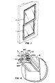
- Fig. 1 there is shown the configuration of double slidable panel windows 1 and 2, the sashes of which are profiles made according to the present invention. The portions of the window frame which interlock on the outer edges of the sashes are not shown.
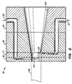
- a die 15 formed from contiguous plates 16, 17, 18 and 19 which will be described in more detail below in connection with Fig. 3.
- Die 15 contains a central orifice 20 which is tapering so as to compress the extrudable material as it passes through the die from right to left as shown.
- a channel 21 communicates among plates 19, 18 and 17 to apply the capstock material to a surface of the core material being compressed and extruded through the orifice 20.
- a second channel 22 is provided communicating among plates 19, 18, 17 and 16 to direct the flexible material to form the various flanges into the orifice 20.
- the capping material is applied to this core extruded material at a location 23 which is upstream from location 24 where the flexible material is applied.
- the flexible material applied at location 24 may be applied onto a surface which comprises the core material or on a surface which comprises the capping material, as desired.
- the profile 25 exits the die 15 as shown by the shadow line and is pulled downstream for further processing such as cooling, sizing, annealing and cutting.
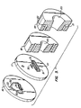
- Plates 16 through 19 which form the complete die 15. Plates 18 and 19 are shown in cross section and parts of plates 16 and 17 are shown in partial cutaway to reveal more detail.
- Plate 19 accommodates the opening to orifice 20 for receiving the core extrudable material and the channels 21 and 22 for receiving the extrudable capping material and flexible material, respectively.
- Plate 18 accommodates a narrower portion of orifice 20 to compress the central core material and contains appropriate passages of channels 21 and 22 for passing the respective extrudable materials into plate 16 or 17.
- Plate 17 defines the profiles for the central core material so that the orifice 20 in plate 18 is now a well defined profile 30. Channel 21 on plate 17 then splits into channels 31 for applying the capping material on the appropriate surfaces at profile 30.
- Plate 16 still defines the profile of the central core at profile 30 but channel 22 splits into subsidiary channels 32 to apply a flexible material as flanges onto the central core material or capping material, as desired. Therefore, in order to change a profile of the window sash, or to apply a coating or flange to different surfaces, plates 16, 17 and 18 may be changed with other plates having different profiles 30 and different channels 31 and 32 for applying the various extrudable materials at desired places.
- the plates 18 and 19 may be used in combination with different sets of plates 16 and 17.
- Fig. 4 there is shown a completed profile 25 exiting from plate 16.
- the core foam material 40 forms most of the profile.
- a thin layer of the capping material 41 is coated on a lower surface of profile 25 which is intended to be the exterior facing surface of the window sash.
- Flexible flanges 42A, 42B and 42C form seals for accommodating the glass panes which are to be inserted into a slot defined by the profile.
- Flexible flanges 43 are provided to form seals with the grooves of the exterior portion of the window frame (not shown).
- Flange 44 is provided to deflect moisture and to avoid moisture collection on the lower lip of the surface 41, since as shown this profile will be attached such that the left side of the profile will be downwardly facing in the window frame.
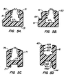
- FIG. 5A comprises a horizontal piece on the window sash and comprises the central foam material 50, capping material 51 which extends around most of the outer surfaces of the core material 50, and flexible flanges 52 for accommodating glass panes.
- This configuration also contains a weep well 53 for collecting moisture and condensation. Appropriate drain holes (not shown) maybe drilled in the bottom of this well to allow moisture to be cleared.
- FIG. 5B there is shown another horizontal member of the window sash which comprises the central core material 60 and capping material 61 which covers only the exterior facing surface of the profile.
- Flexible flanges 62 are provided to accommodate the window panes and there is a condensation/weep well 63. In this profile there is also a flexible flange 64 for deflecting moisture.
- a vertical member of the window sash comprising core material 70 and capping material 71.
- Flexible flanges 72 are provided as sealers for glass panes and there is a condensation/weep well 73.
- Fig. 5D there is shown the same profile that is shown in Fig. 4 comprising core material 40, capping material 41, and flexible flanges 42A, 42B and 42C.
- Flexible flanges 43 and 44 are shown in more detail in Fig 5D.
- the flexible material 40 used to form flanges 43 and 44 has also been extended to form thin waterproof films 43A and 44A made of the same material.
- the flange may be extruded onto the core material, and the capstock may be extruded at the final stage of the triple extrusion process. While this would require some modification of the die, such an alternative is an equivalent to the process described herein.
- a core material was formed from the following ingredients using the indicated parts: Chemical Ingredient Supplier & Trade Name Parts Chlorinated Polyvinyl Chloride Resin (67% Chlorine by Weight) Temprite 627x563 80.000 BF Goodrich Polyvinyl Chloride Resin Vista 5305 20.000 Vista Chemicals Alkyl Tin Mercaptide Stabilizer Mark 1924 4.25 Witco Chemicals Acrylic Process Modifier Paraloid KM-318F 5 Rohm & Haas Acrylic Process Aid Paraloid K-125 1.5 Rohm & Haas Calcium Carbonate Filler Atomite 5 English China Clay Calcium Stearate Lubricant Synpro 92F 1 Synpro Ester Wax Loxiol VGE 1875 2.1 Henkel Corporation Oxidized Polyethylene Wax AC-629A 0.7 Allied Chemical Azodicarbonamide Celogen AZRV 0.15 Uniroyal Chemical Titanium Dioxide Tronox CR-822 1 Kerr McGee
- the die may be fed with a two inch screw-type extruder which is heated in various zones, preferably in zones in temperatures of 138 to 177°C (280° to 350° F), 143 to 179°C (290° to 355° F) 149 to 182°C (300° to 360° F), 154 to 185°C (310° to 365° F), and 160 to 188°C (320° to 370° F), with the die being in at a temperature between 154 and 179°C (310° and 355° F).
- a two inch screw-type extruder which is heated in various zones, preferably in zones in temperatures of 138 to 177°C (280° to 350° F), 143 to 179°C (290° to 355° F) 149 to 182°C (300° to 360° F), 154 to 185°C (310° to 365° F), and 160 to 188°C (320° to 370° F)
- the die being in at a temperature between 154 and 179
- Reduction of lubricants, increase in modifiers or extrusion aids, and reduction in blowing agent may also reduce bubbling. Passing the extrusion mixture through an 3.2 mm (1/8 inch) hole breaker plate instead of a ring prior to the die may also reduce formation of gas bubbles. Evidence of yellowing or burning of the material as it exits the die indicates that the temperature should be lowered or extrusion rates increased. The combination of chlorinated PVC and PVC foam will usually self-clean the die, therefore the operation need not be stopped for cleaning. If the temperature is too high and there is burning shown by yellowing of the extruded material the temperature should be reduced unless temperature reduction results in bubbling in which case cooling rates can be increased.
- stabilizer loading may be increased to reduce burning.
- external lubricants maybe interchanged, for example, highly active external unoxidized polyethylene waxes or polyprophylene waxes may be used. If the extruded material inadequately fills out the corners of the profile, air cooling of the extrusion screw should first be attempted or the die temperatures maybe increased, if that is still possible without burning. Increase in modifier level or acrylic levels and/or decrease of external lubricant levels may also mitigate the problem.
- Capstock material used is General Electric Geloy 1120 (ASA) (color: white 941 or driftwood 850).
- the flexible material is CD-02247 made by Rimtech.
- Window sashes made as above were formed into windows and tested by conventional industry standard tests for operating force (force used to open the window sash), air infiltration, water infiltration, uniform structural load, and thermal performance pursuant to test procedures set forth under test methods AAMA 101V-86, AAMA 1604.1-88, ASTM C2376-87, ASTM D4216, ASTM D4726, ASTM D4099, ASTM F588, F842, ASTM 4803, and ASTM draft E06.51.
- the windows passed all the standards according to these tests.
- the windows were tested for flame and smoke by the E-85 tunnel test (Underwriters Laboratories test method 723) and for vertical burn (Underwriters Laboratories test method 94) and met industry standards.
Abstract
Description
- The present invention is directed to triple extruded frame profiles, preferably window sashes, comprising an extruded body of foam plastic, a co-extrusion coating on at least one surface of the foam plastic, and at learnt one co-extruded flange on the coating or foam plastic. A method is provided for producing a triple extruded window sash member.
- GB-A-2 157 614 discloses a method and apparatus for extruding foamable plastic to form a window sill having an unfoamed exterior extruded skin.
- Due to the increasing cost of wood and the attendant cost of detailing wood pieces for building construction, there is a demand for alternatives to solid wood construction products. A particularly detailed piece used in construction of homes and other buildings is a wood window frame, particularly the two panel sliding sashes (double hung) wherein the panels lock together when in the closed position. This type of window requires intricate wood detailing since the profiles of the sashes require grooves to interlock with the exterior (immovable) portion of the window frame, as well as grooves to accommodate single and double pane glass, as desired. The invention may also be used to manufacture other profiles, such as round top, tilt, casement, etc.
- Typically, wood sashes are made by intricate cuts into solid pieces of wood, with the final assembly, such as cutting drainage ports, waterproofing and sealing, done by hand. The present invention obviates the need for much of this handwork, while also providing an energy-efficient, durable, and low maintenance product.
- A particular advantage of the present invention is that frame profiles may be provided which are energy efficient by use of materials which are more insulative than wood without the need for metal (such as aluminum) sealing or weather-protection. The use of metal on a frame profile diminishes insulative properties. The energy-conservation considerations are particularly important in view of increasingly stringent energy rating compliance standards for windows based on NFRC (National Fenestration Rating Council) U-Values which are being imposed by building code jurisdictions. To meet or exceed these standards, it is desirable to provide a frame profile which is not solid wood, requires minimal hand-work, and which avoids use of metal or energy-inefficient butyl rubber sea lers between the glass panes and frame profile.
- The present invention provides frame profiles that are not made of solid wood and which can be formed by a triple co-extrusion process whereby the core material of the frame profile is an extrudable foam plastic, at least partially coated with a weather-resistant plastic co-extrusion coating, and further co-extruded with a fluid material to form flexible flanges or ridges to provide sealing and water deflection where desired. The present invention also provides a triple co-extrusion die for making such extruded profiles.
- It is therefore an object of the present invention to provide an improved method for making an extruded window sash comprising a foam plastic core material, an outer weather-resistant coating and flexible flanges for sealing and/or water deflection on the coating or core material.
- It is a further object of the present invention to provide improved, elongated frame members made of synthetic materials which have improved energy-ratings and which are formed by a triple extrusion process.
- It is yet another object of the present invention to provide extrusion dies for triple extrusion of a foam core material, a coating material and flexible flange forming material.
- These and other objects will be apparent from the following description and claims, and from practice of the invention.
- The present invention provides a process for forming by extrusion a profile of extrudable material having a coating on at least one portion of its surfaces and at least one flange attached to the coating or extrudable material. The flange is a material different from the coating material. The process comprises the step of extruding the core material in a compression stage by passage through an orifice of a predetermined profile, applying to at least one surface of the extruded material a second material in fluid form in a coating stage within the orifice, then applying to the core material or coating in a flange-forming stage within the orifice a third material whereby the third material is extruded through a slot within the orifice to form a strip, one edge of which is in contact with the coating or core material, to thereby to form a flange; then withdrawing the profile from the orifice and subjecting it to conditions for setting the extrudable material, the coating and third material, whereby such materials solidify and the coating becomes securely bonded to the core material and the flange becomes securely attached to the coating or core material. By use of this method, the present invention provides an extruded profile comprising an extruded body of core material, of foam plastic, a coating which is co-extruded with the core, and a co-extruded flange securely attached to the profile. An extrusion die is provided comprising a tapering orifice for compressing the core material whereby the profile at the compressed end of the orifice is of a predetermined shape; a first opening communicating with the orifice for applying a second extrudable fluid coating onto the compressed material within the orifice as the compressed material passes therethrough, and a second opening in the form of a slot communicating with the orifice for applying a third extrudable material therethrough to form a flange attached to the profile.
-
- In the accompanying drawings, Fig. 1 is a perspective view the type of slidable windows which may be made from sashes made according to the present invention.
- Fig. 2 is a side cross-sectional view of a preferred die according to the present invention for forming a triple extruded profile.
- Fig. 3 is an exploded perspective view of disks which comprise a die according to the present invention, with some of the disks being in partial cross section.
- Fig. 4 is a perspective view of a triple extruded window sash as it emerges from the die.
- Figs. 5A, 5B, 5C and 5D are preferred profiles of window sashes made according to the present invention.
-
- The triple extruded profiles according to the present invention are formed of three extrudable materials with the core being a compressible foam plastic. Since the core material will comprise most of the volume of the extruded profile, its physical characteristics will primarily define the strength and durability of the profile. Synthetic materials are preferably used and will preferably contain PVC or CPVC resins with minor amounts of additives such as process aids, process modifiers, solid fillers, and lubricants for the extrusion process and curing compounds. Process aids are materials which are known to adjust extrudability properties, thus allowing for optimization of extrusion conditions. Process modifiers are additives for adjusting physical properties of the extruded product. It is preferred that this material be extruded under sufficient compression to result in an end product (before curing and drying) of a specific gravity of about 0.60 ± 0.1 gram per cubic centimeter. This specific gravity allows the construction of windows which comply with energy-ratings which are higher than solid-wood profile windows. The preferred materials produce profiles which are about 2.5 times more thermally efficient than solid wood. The primary component of the core material is preferably a chlorinated polyvinyl chloride resin which will comprise at least 50% by weight of the extrudable composition (not including water), and preferably about 65 ± 15% by weight of the extrudable composition. Another component used in place of, or preferably in combination with, the chlorinated polyvinyl chloride resin is polyvinyl chloride resin, which will comprise at least about 10% of the extrudable composition (excluding water) and preferably about 15% ± 5% of the composition.
- The remaining portions of the core composition will comprise stabilizers, acrylic materials, fillers lubricants and stabilizers.
- The materials can be formed into an extrudable mixture by mixing all of the ingredients in random order at virtually any temperature below about 138°C (280°F). The preferred method of forming the core extrudable mixture is to mix the ingredients in a high intensity mixer, such as those produced by Littleford or Henschel. Typically, the polyvinyl chloride (PVC) and chlorinated polyvinyl chloride (CPVC) resins will be mixed in a high intensity mixer and monitored as the heat builds up to approximately 65.6°C (150°F), at which point a resin stabilizer such as alkyl tin mercaptide will be added. Other stabilizers may be used, depending upon the resins used in the core. The CPVC resins typically contain 63-70% chlorine. When the temperature rises to approximately 87.7°C (190°F), the acrylic process aids and modifiers, such as Paraloid KM-318F and K-125 (Rohm and Hass), and a filler such as calcium carbonate, are added. Other fillers may be used, such as talc, wallastonite, clay, mica, etc. Typically, filler loadings up to about 15% by weight are preferred. Other modifiers may be used, such as ADS, MDC and polymethyl methacrylates. With continued mixing the temperature rises, so at about 104°C (220°F) the remaining ingredients may be added, such as lubricants (calcium stearate, ester waxes, polyethylene waxes), blowing agents (such as azodicarbonamide, baking soda, baking soda/citric acid, p-toluene sulfonyl hydrazide, diphenyloxide -4, 4' - disulphohydrazide, and p-toluene sulfonyl semicarbazide) and more fillers, such as titanium dioxide. When the temperature reaches about 124°C (255°F), the contents are preferably discharged to a cooler where the batch is allowed to cool to about 60°C (140°F) whereupon it is ready for extrusion.
- It will be realized that other extrudable materials may be used as the core, including, but not limited to styrene maleic anhydride (SMA), acrylonitrile butadiene styrene (ABS), styrene acrylonitrile (SAN, including alpha-methyl and methyl methacrylate types), blends of PVC/ABS, PVC/polyimide, PVC/SMA, PVC/SAN, PVC/CPVC/polyimide, PVC/CPVC/SMA, PVC/CPVC/SAN, CPVC/ABS, CPVC/polyimide, CVPC/SMA, CPVC/SAN, ABS/SAN, ABS/SMA, ABS/SAN/SMA, SMA/SAN, and the like. In addition, fibers may be added to enhance stiffness, impart a higher use temperature for hot climates and reduce expansion/contraction with thermal changes. Milled or chopped glass, wood, cellulose, Kevlar™, ceramics, polyesters, and the like, may serve this purpose. Also, unused extruded product may be reground and recycled into the extrusion melt.
- Extrudability is improved if the mixture is allowed to age before extruding, usually from around 24 hours and above, but not longer than about one month. If aged too long, the texture changes but the mixture can be reblended for a few minutes to again obtain the homogeneity necessary for extrusion. During the aging process the mixture will typically absorb water from the atmosphere, which may change the texture. The extrudability of the mixture may change since moisture acts as a plasticizer and blowing agent. Thus, if the moisture is increased, the lubricants in the composition may be increased, as well as the stabilizer levels, while also decreasing the amount of blowing agent to compensate for the additional moisture. Increasing the lubricant and stabilizer level sometimes adversely affects the flow characteristics of the composition and therefore, if needed, a flow aid such as fumed silica (such as Syloid 74 made by Davison Chemical Company) may be added in minor amounts, such as, for example 0.25%, to assist the flow of the composition. Because of the difference in moisture uptake during summer and winter, it may be more convenient to formulate different compositions for use for extrusion during the summer months and another for the rest of the year.
- Ideal extrusion conditions may vary but it is most useful to extrude through a 5 to 9 cm (2 to 3.5 inch) single screw extruder. Twin screw extruders may be used to increase the extrusion rate, and/or increase density.
- It is also preferred that the die be thermally balanced for the composition which is extruded at a predetermined melt temperature. In general, it is preferred to balance the die at the lower end of the temperature range which is acceptable for the extrusion.
- The second material feeding through the die is a coating material, also known as a capstock, which is extruded to form a thin, protective layer over the foam core material to protect it from the weathering effects of water and exposure to sunlight. It is believed that any conventional capstock can be used which is known for this purpose, provided that it is compatible with the core foam material and is extrudable in about the melt temperature range of the foam. The preferred materials for the capstock are acrylic styrene acrylonitrile (ASA) and blends of ASA with polyvinyl chloride. The ASA is most preferred. These materials are commercially available such as Geloy 1120 (General Electric), which comes in various colors. The ASA/PVC blends are also commercially available, such as Geloy XP-1001-100 (an ASA material), which also comes in various colors. Other capstock materials include, but are not limited to, semi-rigid PVC (Duracap™), acrylics, acrylic blends and CPVC.
- The third material which is co-extruded in the die with the core material and the capstock is a flexible material which is used to form flanges and/or seals. The flexible material must have sufficient cold and hot temperature properties to resist prolonged exposure to weather and sunlight and also must be sufficiently soft so that it can flex and form a seal with glass panes. However, it must not be too soft in the die. If so, when it is treated with downstream equipment, such as vacuum sizers, it is permanently deformed. The flexible material should also be compatible with the core resin and capstock material to which it is to be bonded. The components of the flexible material must also be physically stable to the extrusion and other processing temperatures so that plasticizers do not migrate to leave it in a brittle condition or vaporized to fog the glass which is eventually, fitted within the profile. Many materials which are commercial meet these criteria. Preferably, the flexible material is Chemigum™ TPE 03080 Natural, a material made by Goodyear with a Shore A hardness of 80. Materials with Shore A hardness in the range of about 65-90 may be used, such as, Alcryn™ (Dupont), thermo-plastic polyurethane (Dow, BASF), NBR rubber, etc.
- After extrusion through the die the materials are cooled, preferably in a water-cooled vacuum tank by pulling the profile through the tank. The cooling period should be adjusted to obtain optimum properties. If the profile is not adequately cooled, such as by pulling the profile too quickly through the tank, the melt may be stretched. The rate of extrusion is also dependent upon the vacuum maintained in the vacuum tank since the greater the vacuum the more tendency for the angles on profile to be maintained at the desired level. If the profile is pulled too fast through the tank the melt may collapse after exiting the vacuum sizer. It is therefore preferred that the profile be passed through a second sizer in the vacuum tank and that conventional methods of maintaining profiles be used such as a spreader bar to prevent profile collapse at fast pulling speeds. Preferably at least two vacuum pumps on the vacuum tank are used to maintain desired dimensions during an extrusion. Uniform temperatures within the tanks may be maintained by circulating water sprayers.
- After exiting the vacuum tank and sizers, conventional means to correct warpage may be used, such as heat guns applied to areas to relieve stress and warpage which may have been incurred in the cooling and sizing operations.
- The profiles of the preferred materials are then annealed before cutting to desired lengths. The annealing is preferably conducted by supporting the profiles in appropriate places in a heating oven at a temperature between about 49°C and 87.7°C (120° and 190°F), preferably about 73.9-79.4°C (165°-175°F), for from about 8 hours to 24 hours, preferably about 12 hours, at low relative humidities, usually about 15% to 20%. These are preferred conditions for the preferred materials according to the present invention but it will be realized that these conditions may be adjusted to determine the most desirable annealing conditions depending on the particular materials used.
- Turning now to the figures, in Fig. 1 there is shown the configuration of double slidable panel windows 1 and 2, the sashes of which are profiles made according to the present invention. The portions of the window frame which interlock on the outer edges of the sashes are not shown.
- Referring to Fig. 2 there is shown a die 15 formed from
contiguous plates central orifice 20 which is tapering so as to compress the extrudable material as it passes through the die from right to left as shown. As shown, achannel 21 communicates amongplates orifice 20. Asecond channel 22 is provided communicating amongplates orifice 20. As shown in the figure the capping material is applied to this core extruded material at alocation 23 which is upstream fromlocation 24 where the flexible material is applied. The flexible material applied atlocation 24 may be applied onto a surface which comprises the core material or on a surface which comprises the capping material, as desired. Theprofile 25 exits the die 15 as shown by the shadow line and is pulled downstream for further processing such as cooling, sizing, annealing and cutting. - Referring to Fig. 3 there are shown the
plates 16 through 19 which form thecomplete die 15.Plates plates Plate 19 accommodates the opening to orifice 20 for receiving the core extrudable material and thechannels Plate 18 accommodates a narrower portion oforifice 20 to compress the central core material and contains appropriate passages ofchannels plate Plate 17 defines the profiles for the central core material so that theorifice 20 inplate 18 is now a well definedprofile 30.Channel 21 onplate 17 then splits intochannels 31 for applying the capping material on the appropriate surfaces atprofile 30. -
Plate 16 still defines the profile of the central core atprofile 30 butchannel 22 splits intosubsidiary channels 32 to apply a flexible material as flanges onto the central core material or capping material, as desired. Therefore, in order to change a profile of the window sash, or to apply a coating or flange to different surfaces,plates different profiles 30 anddifferent channels plates plates - Referring now to Fig. 4 there is shown a completed
profile 25 exiting fromplate 16. In the particular embodiment shown thecore foam material 40 forms most of the profile. A thin layer of the cappingmaterial 41 is coated on a lower surface ofprofile 25 which is intended to be the exterior facing surface of the window sash.Flexible flanges Flexible flanges 43 are provided to form seals with the grooves of the exterior portion of the window frame (not shown).Flange 44 is provided to deflect moisture and to avoid moisture collection on the lower lip of thesurface 41, since as shown this profile will be attached such that the left side of the profile will be downwardly facing in the window frame. - Referring to Figure 5, there are shown various profiles for different portions of the window sash. The profile shown in Fig. 5A comprises a horizontal piece on the window sash and comprises the
central foam material 50, cappingmaterial 51 which extends around most of the outer surfaces of thecore material 50, andflexible flanges 52 for accommodating glass panes. This configuration also contains a weep well 53 for collecting moisture and condensation. Appropriate drain holes (not shown) maybe drilled in the bottom of this well to allow moisture to be cleared. - Referring to Fig. 5B there is shown another horizontal member of the window sash which comprises the
central core material 60 and cappingmaterial 61 which covers only the exterior facing surface of the profile.Flexible flanges 62 are provided to accommodate the window panes and there is a condensation/weep well 63. In this profile there is also aflexible flange 64 for deflecting moisture. - Referring to Fig. 5C there is shown a vertical member of the window sash comprising
core material 70 and cappingmaterial 71.Flexible flanges 72 are provided as sealers for glass panes and there is a condensation/weep well 73. - Referring to Fig. 5D there is shown the same profile that is shown in Fig. 4 comprising
core material 40, cappingmaterial 41, andflexible flanges Flexible flanges flexible material 40 used to formflanges waterproof films - For example, the flange may be extruded onto the core material, and the capstock may be extruded at the final stage of the triple extrusion process. While this would require some modification of the die, such an alternative is an equivalent to the process described herein.
- Having described the preferred embodiments of the present invention, the following examples are not intended to limit the invention in any way.
- A core material was formed from the following ingredients using the indicated parts:
Chemical Ingredient Supplier & Trade Name Parts Chlorinated Polyvinyl Chloride Resin (67% Chlorine by Weight) Temprite 627x563 80.000 BF Goodrich Polyvinyl Chloride Resin Vista 5305 20.000 Vista Chemicals Alkyl Tin Mercaptide Stabilizer Mark 1924 4.25 Witco Chemicals Acrylic Process Modifier Paraloid KM-318F 5 Rohm & Haas Acrylic Process Aid Paraloid K-125 1.5 Rohm & Haas Calcium Carbonate Filler Atomite 5 English China Clay Calcium Stearate Lubricant Synpro 92F 1 Synpro Ester Wax Loxiol VGE 1875 2.1 Henkel Corporation Oxidized Polyethylene Wax AC-629A 0.7 Allied Chemical Azodicarbonamide Celogen AZRV 0.15 Uniroyal Chemical Titanium Dioxide Tronox CR-822 1 Kerr McGee - The above ingredients are blended in the following manner:
- 1. Add to the Littleford or Henschel Mixer (A high intensity mixer) the PVC and CPVC resins.
- 2. Turn the mixer on to high speed.
- 3. When the heat builds up to 65.6°C (150 F) add to the mixer the Mark 1924 Stabilizer.
- 4. When the mixer temperature reaches 87.7°C (190 F) add the Paraloid KM-318F, Paraloid K-125, and the Atomite.
- 5. At 104°C (220 F) add the remaining ingredients.
- 6. When the temperature reaches 110°C (230° F) discharge the contents of the mixer to the cooler.
- 7. Cool the batch in the cooler to 60°C (140 F) and then discharge the blend to an appropriate container for extrusion.
-
- The mixture described above is used to form window sashes such as those shown in the accompanying figures.
- The die may be fed with a two inch screw-type extruder which is heated in various zones, preferably in zones in temperatures of 138 to 177°C (280° to 350° F), 143 to 179°C (290° to 355° F) 149 to 182°C (300° to 360° F), 154 to 185°C (310° to 365° F), and 160 to 188°C (320° to 370° F), with the die being in at a temperature between 154 and 179°C (310° and 355° F). As is typical in extrusion processes, if gas bubbles form higher temperatures in the first two zones will obviate this problem. Reduction of lubricants, increase in modifiers or extrusion aids, and reduction in blowing agent may also reduce bubbling. Passing the extrusion mixture through an 3.2 mm (1/8 inch) hole breaker plate instead of a ring prior to the die may also reduce formation of gas bubbles. Evidence of yellowing or burning of the material as it exits the die indicates that the temperature should be lowered or extrusion rates increased. The combination of chlorinated PVC and PVC foam will usually self-clean the die, therefore the operation need not be stopped for cleaning. If the temperature is too high and there is burning shown by yellowing of the extruded material the temperature should be reduced unless temperature reduction results in bubbling in which case cooling rates can be increased. Alternatively, in combination with the above solutions to bubbling and burning, stabilizer loading may be increased to reduce burning. Alternatively, external lubricants maybe interchanged, for example, highly active external unoxidized polyethylene waxes or polyprophylene waxes may be used. If the extruded material inadequately fills out the corners of the profile, air cooling of the extrusion screw should first be attempted or the die temperatures maybe increased, if that is still possible without burning. Increase in modifier level or acrylic levels and/or decrease of external lubricant levels may also mitigate the problem. Capstock material used is General Electric Geloy 1120 (ASA) (color: white 941 or driftwood 850). The flexible material is CD-02247 made by Rimtech.
- Window sashes made as above were formed into windows and tested by conventional industry standard tests for operating force (force used to open the window sash), air infiltration, water infiltration, uniform structural load, and thermal performance pursuant to test procedures set forth under test methods AAMA 101V-86, AAMA 1604.1-88, ASTM C2376-87, ASTM D4216, ASTM D4726, ASTM D4099, ASTM F588, F842, ASTM 4803, and ASTM draft E06.51. The windows passed all the standards according to these tests. In addition, the windows were tested for flame and smoke by the E-85 tunnel test (Underwriters Laboratories test method 723) and for vertical burn (Underwriters Laboratories test method 94) and met industry standards.
Claims (12)
- A method of forming a solid, elongated frame member of predetermined profile comprising an extruded body of foam plastic having a U-shaped channel formed therein, a coating (41; 51;61;71) on at least a portion of the surface of said member and at least one flange (42A,42B,42C;43,44;52; 62;72) attached to said member, said flange being of a flexible material, comprising the steps of:compressing an extrudable foam plastic material (40;50;60;70) at a compression stage by passage through an orifice (20), said orifice (20) having at one end thereof said predetermined profile (30);applying to at least one surface of said foam plastic material at a coating stage within said orifice (20) subsequent to said compression stage, a fluid coating material;applying to said foam plastic material and/or said coating material at a flange-forming stage within said orifice (20) a flexible material in fluid form whereby said flexible material is extruded through at least one slot in said orifice (20) to form a flange (42A,42B,42C; 43,44;52;62;72), one edge of which is in contact with said coating and/or said foam plastic material, thereby forming said member;withdrawing said member from said orifice (20) and setting said foam plastic material, coating material and flexible material whereby said coating (41;51;61;71) solidifies and is securely bonded to said foam plastic material (40;50;60; 70) and said flexible material solidifies to a flexible flange (42A,42B,42C;43,44;52; 62;72) securely attached to said member.
- A method as claimed in claim 1 wherein said member is a window sash.
- A method as claimed in either of claims 1 and 2 wherein said foam plastic material (40;50;60;70) comprises chlorinated polyvinyl chloride resin and optionally polyvinyl chloride resin.
- A method as claimed in any preceding claim wherein said coating material (41;51;61;71) comprises acrylic styrene acrylonitrile polymer and optionally polyvinyl chloride.
- A method as claimed in any preceding claim wherein said flexible material comprises polyvinyl chloride.
- A method as claimed in any preceding claim further comprising the step of annealing said profile piece at a temperature in a range of about 55 to 87.7°C (120° to 190°F) for a period of about 8 to 24 hours at a relative humidity within the range of 15-20%.
- An extruded solid elongated member comprising an extruded body of foam plastic having a U-shaped channel formed therein, at least one flexible flange (42A,42B, 42C;52;62;72) coextruded therewith along the interior of said U-shaped channel, said flange comprising flexible material, and a coextruded coating (41;51;61;71) on at least a portion of the outside surface of said extruded body.
- An extruded member as claimed in claim 7 wherein said member is a window sash comprising a plurality of said flanges (42A,42B,42C;52;62;72) which comprise flexible edges for sealing glass panes.
- An extruded member as claimed in claim 8 comprising a flange (64) for deflecting runoff water from said sash.
- An extruded member as claimed in any of claims 7 to 9 wherein said foam plastic (40;50;60;70) comprises chlorinated polyvinyl chloride and optionally polyvinyl chloride resin.
- An extruded member as claimed in any of claims 7 to 10 wherein said coextruded coating (41;51;61;71) comprises acrylic styrene acrylonitrile polymer and optionally polyvinyl chloride.
- An extruded member as claimed in any of claims 7 to 11 wherein said flange (42A,42B,42C;52;62;72) comprises polyvinyl chloride.
Applications Claiming Priority (3)
| Application Number | Priority Date | Filing Date | Title |
|---|---|---|---|
| US08/116,153 US5538777A (en) | 1993-09-01 | 1993-09-01 | Triple extruded frame profiles |
| US116153 | 1993-09-01 | ||
| PCT/US1994/008898 WO1995006554A1 (en) | 1993-09-01 | 1994-08-11 | Profiles, die and method for producing same |
Publications (3)
| Publication Number | Publication Date |
|---|---|
| EP0722385A1 EP0722385A1 (en) | 1996-07-24 |
| EP0722385A4 EP0722385A4 (en) | 1996-12-27 |
| EP0722385B1 true EP0722385B1 (en) | 2000-10-11 |
Family
ID=22365571
Family Applications (1)
| Application Number | Title | Priority Date | Filing Date |
|---|---|---|---|
| EP19940925761 Expired - Lifetime EP0722385B1 (en) | 1993-09-01 | 1994-08-11 | Profiles and method for producing same |
Country Status (14)
| Country | Link |
|---|---|
| US (3) | US5538777A (en) |
| EP (1) | EP0722385B1 (en) |
| JP (1) | JPH09501879A (en) |
| CN (1) | CN1061289C (en) |
| AT (1) | ATE196871T1 (en) |
| AU (1) | AU683083B2 (en) |
| CA (1) | CA2170776C (en) |
| DE (1) | DE69426124T2 (en) |
| DK (1) | DK0722385T3 (en) |
| ES (1) | ES2150498T3 (en) |
| GR (1) | GR3035061T3 (en) |
| NZ (1) | NZ271801A (en) |
| PT (1) | PT722385E (en) |
| WO (1) | WO1995006554A1 (en) |
Families Citing this family (67)
| Publication number | Priority date | Publication date | Assignee | Title |
|---|---|---|---|---|
| US5538777A (en) * | 1993-09-01 | 1996-07-23 | Marley Mouldings Inc. | Triple extruded frame profiles |
| DE29610642U1 (en) * | 1996-06-18 | 1996-10-02 | Voss Chemie | Foam strips |
| US5698057A (en) * | 1996-08-26 | 1997-12-16 | Chrysler Corporation | Method of manufacturing a composite structural member for an automobile |
| AU719275B2 (en) | 1996-11-21 | 2000-05-04 | Marley Mouldings Inc. | Weatherstrip product formed by sequential extrusion of cellular and non-cellular plastic resins |
| AU5220398A (en) * | 1996-12-13 | 1998-07-03 | Lubo Krizik | Method of making foam/concrete building panels |
| US5789453A (en) * | 1997-04-10 | 1998-08-04 | The B. F. Goodrich Company | Medium density chlorinated polyvinyl chloride foam and process for preparing |
| US6406785B1 (en) * | 1998-07-16 | 2002-06-18 | Schlegel Corporation | Weatherseal having a contact layer with thermoplastic particles in a thermoset carrier |
| IL131556A0 (en) * | 1998-10-27 | 2001-01-28 | Premark Rwp Holdings Inc | A process and apparatus for extrusion |
| US6131521A (en) * | 1998-11-17 | 2000-10-17 | Premark Rwp Holdings, Inc. | Modular worktops, method of assembly and method of use therefore |
| US6784216B1 (en) | 1999-04-28 | 2004-08-31 | Crane Plastics Company Llc | ABS foam and method of making same |
| US6260251B1 (en) | 1999-08-31 | 2001-07-17 | Andersen Corporation | Unitary profile for window construction |
| KR20100035666A (en) | 1999-11-23 | 2010-04-05 | 메틸진 인크. | Inhibitors of histone deacetylase |
| US20040142160A1 (en) * | 2000-03-06 | 2004-07-22 | Mikron Industries, Inc. | Wood fiber polymer composite extrusion and method |
| US6660086B1 (en) | 2000-03-06 | 2003-12-09 | Innovative Coatings, Inc. | Method and apparatus for extruding a coating upon a substrate surface |
| US6658802B2 (en) | 2000-10-24 | 2003-12-09 | Northwest Rubber Extruders, Inc. | Seal for fixed window of motor vehicle with curved concave corners |
| US6405500B1 (en) | 2000-10-24 | 2002-06-18 | Northwest Rubbersextruders, Inc. | Seal for fixed window of motor vehicle |
| CA2361992A1 (en) * | 2000-11-13 | 2002-05-13 | Mikronwood, Llc | Multi-component coextrusion |
| US6863972B2 (en) * | 2001-01-09 | 2005-03-08 | Crane Plastics Company Llc | Synthetic wood component having a foamed polymer backing |
| US6534147B2 (en) | 2001-02-15 | 2003-03-18 | Schlegal Corporation | Composite weatherstrip having a friction reducing surface coating on a hard bearing layer |
| US6592789B2 (en) * | 2001-05-18 | 2003-07-15 | James B. Barsby | Apparatus and methods for mixing and injecting a foam core within an extruded shell |
| US6696011B2 (en) * | 2001-07-02 | 2004-02-24 | Sun Young Yun | Extruding and blow-molding method for forming a plastic product |
| US6458301B1 (en) | 2001-08-27 | 2002-10-01 | Schlegel Corporation | Method for forming weatherseals from an interchangeable insert die assembly |
| US6783348B2 (en) * | 2001-09-26 | 2004-08-31 | Korea Plasys Corporation | Extrusion molding apparatus for product having wood pattern and extrusion molding method thereof |
| US6817651B2 (en) * | 2002-05-01 | 2004-11-16 | Schlegel Corporation | Modular vehicular window seal assembly |
| ITTO20021089A1 (en) * | 2002-12-17 | 2004-06-18 | Metzeler Automotive Profile | EQUIPMENT FOR THE EXTRUSION OF A COMPOSITE DRAWN. |
| US7001165B2 (en) * | 2003-05-02 | 2006-02-21 | Certainteed Corporation | Sizer for forming shaped polymeric articles and method of sizing polymeric articles |
| EP1484149A1 (en) * | 2003-06-05 | 2004-12-08 | Nmc S.A. | Method for continuous production of solid, hollow or open profiles |
| US20050006804A1 (en) * | 2003-07-08 | 2005-01-13 | Steven Hartman | Extrusion apparatus and method and extruded foam article |
| CA2445094A1 (en) * | 2003-10-15 | 2005-04-15 | Royal Group Technologies Limited | Extruded foam plastic frame members |
| US20050129911A1 (en) * | 2003-12-12 | 2005-06-16 | Schlegel Corporation | Surface treated particulated polymeric matrix for forming an exposed surface of a weatherseal |
| TW200535320A (en) * | 2004-03-17 | 2005-11-01 | Premdor International Inc | Wood-plastic composite door jamb and brickmold, and method of making same |
| US9920177B2 (en) | 2004-06-04 | 2018-03-20 | Nmc S.A. | Continuous method for producing solid, hollow or open profiles |
| US20060086053A1 (en) * | 2004-10-27 | 2006-04-27 | Peter John Ellis | Lightweight glass-run channels |
| US20060103045A1 (en) * | 2004-11-17 | 2006-05-18 | O'brien-Bernini Frank C | Wet use chopped strand glass as reinforcement in extruded products |
| US8074339B1 (en) | 2004-11-22 | 2011-12-13 | The Crane Group Companies Limited | Methods of manufacturing a lattice having a distressed appearance |
| AT501156B8 (en) * | 2004-12-23 | 2007-02-15 | Topf Kunststofftechnik Ges M B | EXTRUSION NOZZLE FOR EXTRUDING HOLLOW PROFILES |
| US20070020475A1 (en) * | 2005-07-21 | 2007-01-25 | Prince Kendall W | Primed substrate and method for making the same |
| US8167275B1 (en) | 2005-11-30 | 2012-05-01 | The Crane Group Companies Limited | Rail system and method for assembly |
| US20070141316A1 (en) * | 2005-12-19 | 2007-06-21 | Mcgrath Ralph D | Tri-extruded WUCS glass fiber reinforced plastic composite articles and methods for making such articles |
| US20070148429A1 (en) * | 2005-12-19 | 2007-06-28 | Mcgrath Ralph D | Tri-excluded WUCS glass fiber reinforced plastic composite articles and methods for making such articles |
| US7743567B1 (en) | 2006-01-20 | 2010-06-29 | The Crane Group Companies Limited | Fiberglass/cellulosic composite and method for molding |
| DE102006011933B4 (en) * | 2006-03-15 | 2010-04-15 | Baerlocher Gmbh | Stabilizer compositions for halogen-containing polymers having improved initial color and improved color retention, polymer compositions containing them and shaped articles, and methods for stabilizing halogen-containing polymers |
| US8460797B1 (en) | 2006-12-29 | 2013-06-11 | Timbertech Limited | Capped component and method for forming |
| US9289795B2 (en) | 2008-07-01 | 2016-03-22 | Precision Coating Innovations, Llc | Pressurization coating systems, methods, and apparatuses |
| US20100015456A1 (en) | 2008-07-16 | 2010-01-21 | Eastman Chemical Company | Thermoplastic formulations for enhanced paintability toughness and melt process ability |
| US20100037548A1 (en) * | 2008-08-18 | 2010-02-18 | Certainteed Corporation | Roofing Product With Zoned Functional Compositions And Methods Of Making The Same |
| US8632868B2 (en) * | 2009-11-21 | 2014-01-21 | Mikron Industries, Inc. | Integrated insulation extrusion and extrusion technology for window and door systems |
| CN103501979B (en) * | 2011-04-15 | 2016-06-22 | 埃克森美孚化学专利公司 | Extrusion mould and method |
| AU2011202256C1 (en) * | 2011-05-16 | 2012-05-10 | Jeld-Wen Australia Pty Ltd | Track for sliding wardrobe doors and the like |
| EP2538011A1 (en) * | 2011-06-22 | 2012-12-26 | profine GmbH | PVC hollow chamber profile and the use |
| CN103072455B (en) * | 2011-10-25 | 2016-02-03 | 比亚迪股份有限公司 | A kind of sealing strip on outer side of car window and preparation method thereof |
| US9481777B2 (en) | 2012-03-30 | 2016-11-01 | The Procter & Gamble Company | Method of dewatering in a continuous high internal phase emulsion foam forming process |
| CN103373204B (en) * | 2012-04-25 | 2016-11-02 | 比亚迪股份有限公司 | A kind of sealing strip on outer side of car window and preparation method thereof |
| US9616457B2 (en) | 2012-04-30 | 2017-04-11 | Innovative Coatings, Inc. | Pressurization coating systems, methods, and apparatuses |
| CN102817529B (en) * | 2012-08-30 | 2014-07-30 | 大连实德科技发展有限公司 | Self-enhancement plastic profiled bar and production method thereof |
| US8865261B2 (en) | 2012-12-06 | 2014-10-21 | Eastman Chemical Company | Extrusion coating of elongated substrates |
| US9744707B2 (en) | 2013-10-18 | 2017-08-29 | Eastman Chemical Company | Extrusion-coated structural members having extruded profile members |
| US9920526B2 (en) | 2013-10-18 | 2018-03-20 | Eastman Chemical Company | Coated structural members having improved resistance to cracking |
| US20150110996A1 (en) * | 2013-10-18 | 2015-04-23 | Eastman Chemical Company | Extrusion-coated structural systems having integrated hardware elements |
| JP5572272B1 (en) * | 2013-10-21 | 2014-08-13 | キョーセー株式会社 | Cooling and flattening device for flat corner materials |
| GB201400232D0 (en) * | 2014-01-07 | 2014-02-26 | Environmental Technology Evolution Ltd | Ete 1 |
| CN104325616A (en) * | 2014-08-29 | 2015-02-04 | 辽宁程威塑料型材有限公司 | Production method of three-color co-extrusion plastic profile |
| US10486354B2 (en) | 2014-12-17 | 2019-11-26 | Poly-Wood, Llc | Extruded board with realistic appearance |
| CN104626700B (en) * | 2015-01-09 | 2017-05-31 | 陈秉胜 | A kind of composite sectional material plate and its processing technology |
| CN106079353B (en) * | 2016-08-15 | 2018-06-26 | 盐城工学院 | It is a kind of to squeeze out co-extrusion die head and its extrusion method with double conductive section bars |
| JP6262395B1 (en) * | 2016-12-13 | 2018-01-17 | トキワケミカル工業株式会社 | Manufacturing method of extruded products for automobiles |
| DE102018214671A1 (en) * | 2018-08-29 | 2020-03-05 | Greiner Extrusion Group Gmbh | Extrusion device and method |
Family Cites Families (33)
| Publication number | Priority date | Publication date | Assignee | Title |
|---|---|---|---|---|
| US3216068A (en) * | 1961-03-30 | 1965-11-09 | Gen Motors Corp | Seal |
| US3535824A (en) * | 1967-03-02 | 1970-10-27 | Gerald Kessler | Abrasion-resistant rigid-flexible weatherstrip |
| US3685231A (en) * | 1968-12-09 | 1972-08-22 | Werner Blose | Edge protector,moulding or beading |
| US3685206A (en) * | 1970-09-28 | 1972-08-22 | Gerald Kessler | Low-friction abrasion-resistant plastic weatherstrip |
| US3656260A (en) * | 1970-10-26 | 1972-04-18 | Schlegel Mfg Co | Channel held weather seal |
| US3833704A (en) * | 1971-02-24 | 1974-09-03 | Welex Inc | Method of extracting a plural layered sheet |
| GB1456086A (en) * | 1974-04-24 | 1976-11-17 | Schlegel Uk Ltd | Edge protector trim strip |
| GB1509777A (en) * | 1975-09-20 | 1978-05-04 | Deventer Kg | Sliding seal |
| DE2732866A1 (en) * | 1976-07-23 | 1978-01-26 | Progress Plastics Ltd | EXTRUSION PROFILES AND SHAPE HERE |
| US4287749A (en) * | 1979-11-15 | 1981-09-08 | Ford Motor Company | Tapered extrusion die and method of forming the same |
| IT1119627B (en) * | 1979-12-21 | 1986-03-10 | Saiag Spa | GASKET PROFILE FOR VEHICLE BODIES AND PROCEDURE FOR ITS MANUFACTURE |
| US4371273A (en) * | 1981-01-16 | 1983-02-01 | International Business Machines Corporation | Electrochemical printhead |
| US4600461A (en) * | 1983-09-12 | 1986-07-15 | Lof Plastics Inc. | Method of extruding a foamed thermoplastic core and extruding and integrally sealing a non-porous skin thereon |
| US4722818A (en) * | 1984-03-20 | 1988-02-02 | The Standard Products Company | Method for making an elongated composite article |
| DE3415057A1 (en) * | 1984-04-21 | 1985-10-24 | Battenfeld Extrusionstechnik GmbH, 4970 Bad Oeynhausen | METHOD AND TOOL FOR EXTRUDING AT LEAST AREAS OF FOAMED PLASTIC PROFILES |
| US4708351A (en) * | 1984-09-17 | 1987-11-24 | Toyoda Gosei Co., Ltd | Sealed joint including water-absorptive, water-swelling coating at joint interface site for using leakage to repair leaks |
| US4690862B1 (en) * | 1984-12-28 | 1998-03-17 | Gossen Corp | Integral composite profile of cellular and non-cellular resins and dual extension method for its manufacture |
| US4676995A (en) * | 1986-02-24 | 1987-06-30 | Gencorp Inc. | Abrasion resistant coatings |
| JPS62201115U (en) * | 1986-04-07 | 1987-12-22 | ||
| US5112548A (en) * | 1987-10-30 | 1992-05-12 | Color Custom, Inc. | Extrusion method and apparatus for producing a molding strip |
| US4898760A (en) * | 1987-11-17 | 1990-02-06 | Amesbury Industries, Inc. | Process and apparatus for extruding a low density elastomeric thermoplastic foam |
| FR2631413B1 (en) * | 1988-05-16 | 1991-01-25 | Hutchinson | SEAL, IN PARTICULAR FOR MOBILE WINDOW OF MOTOR VEHICLE |
| US5110276A (en) * | 1989-12-28 | 1992-05-05 | Farnsworth John T | Extrusion die assembly |
| US5267739A (en) * | 1990-02-07 | 1993-12-07 | The Standard Products Company | Engine compartment seal |
| CA2035709C (en) * | 1990-02-19 | 1995-04-18 | Tadanobu Iwasa | Rubber shaped articles having a finishing layer and a process for production thereof |
| US5183613A (en) * | 1990-08-22 | 1993-02-02 | Gencorp Inc. | Process for the preparation of solventless, low friction, abrasion-resistant coatings for elastomeric substrates |
| US5403176A (en) * | 1991-02-01 | 1995-04-04 | Gala Industries, Inc. | Tapered insert die plate for underwater pelletizers |
| US5137675A (en) * | 1991-05-13 | 1992-08-11 | Gencorp Inc. | Apparatus and method for coextruding materials having different temperature dependent properties |
| US5326592A (en) * | 1991-05-13 | 1994-07-05 | Gencorp Inc. | On die solution coating of extruded profiles and apparatus therefor |
| JPH0531785A (en) * | 1991-07-30 | 1993-02-09 | Kinugawa Rubber Ind Co Ltd | Manufacture of weatherstrip |
| US5311711A (en) * | 1992-10-30 | 1994-05-17 | Standard Products Company | J-type window lace assemblies |
| US5338087A (en) * | 1993-03-24 | 1994-08-16 | Creative Extruded Products, Inc. | Anti-squeak molding |
| US5538777A (en) * | 1993-09-01 | 1996-07-23 | Marley Mouldings Inc. | Triple extruded frame profiles |
-
1993
- 1993-09-01 US US08/116,153 patent/US5538777A/en not_active Expired - Lifetime
-
1994
- 1994-08-11 NZ NZ271801A patent/NZ271801A/en unknown
- 1994-08-11 CN CN94193228A patent/CN1061289C/en not_active Expired - Fee Related
- 1994-08-11 DE DE1994626124 patent/DE69426124T2/en not_active Expired - Fee Related
- 1994-08-11 WO PCT/US1994/008898 patent/WO1995006554A1/en active IP Right Grant
- 1994-08-11 ES ES94925761T patent/ES2150498T3/en not_active Expired - Lifetime
- 1994-08-11 AT AT94925761T patent/ATE196871T1/en not_active IP Right Cessation
- 1994-08-11 DK DK94925761T patent/DK0722385T3/en active
- 1994-08-11 PT PT94925761T patent/PT722385E/en unknown
- 1994-08-11 EP EP19940925761 patent/EP0722385B1/en not_active Expired - Lifetime
- 1994-08-11 CA CA 2170776 patent/CA2170776C/en not_active Expired - Lifetime
- 1994-08-11 JP JP50812395A patent/JPH09501879A/en active Pending
- 1994-08-11 AU AU75566/94A patent/AU683083B2/en not_active Ceased
-
1995
- 1995-11-01 US US08/551,563 patent/US5795641A/en not_active Expired - Lifetime
-
1998
- 1998-04-10 US US09/058,479 patent/US5965075A/en not_active Expired - Lifetime
-
2000
- 2000-12-13 GR GR20000402749T patent/GR3035061T3/en not_active IP Right Cessation
Also Published As
| Publication number | Publication date |
|---|---|
| CN1061289C (en) | 2001-01-31 |
| DK0722385T3 (en) | 2001-02-05 |
| CA2170776A1 (en) | 1995-03-09 |
| NZ271801A (en) | 1997-07-27 |
| JPH09501879A (en) | 1997-02-25 |
| PT722385E (en) | 2001-01-31 |
| DE69426124D1 (en) | 2000-11-16 |
| ES2150498T3 (en) | 2000-12-01 |
| AU7556694A (en) | 1995-03-22 |
| US5965075A (en) | 1999-10-12 |
| WO1995006554A1 (en) | 1995-03-09 |
| CN1129918A (en) | 1996-08-28 |
| DE69426124T2 (en) | 2001-05-10 |
| AU683083B2 (en) | 1997-10-30 |
| US5538777A (en) | 1996-07-23 |
| US5795641A (en) | 1998-08-18 |
| GR3035061T3 (en) | 2001-03-30 |
| EP0722385A4 (en) | 1996-12-27 |
| CA2170776C (en) | 2004-07-13 |
| ATE196871T1 (en) | 2000-10-15 |
| EP0722385A1 (en) | 1996-07-24 |
Similar Documents
| Publication | Publication Date | Title |
|---|---|---|
| EP0722385B1 (en) | Profiles and method for producing same | |
| US20050257455A1 (en) | Wood-plastic composite door jamb and brickmold, and method of making same | |
| US5592782A (en) | Polymeric sealing/spring strip and exTrusion method of producing same | |
| US5497594A (en) | Advanced polymer and wood fiber composite structural component | |
| AU719275B2 (en) | Weatherstrip product formed by sequential extrusion of cellular and non-cellular plastic resins | |
| CA2259739A1 (en) | Foamed thermoplastic polymer and wood fiber profile and member | |
| US20040142157A1 (en) | Multi-component coextrusion | |
| US6893594B2 (en) | Extruded window and door composite frames | |
| US20090230584A1 (en) | Method for extruding foam plastic frame members | |
| US5522196A (en) | Thin wall profile having outer weather band ultra violet light resistant layer | |
| WO1993023649A1 (en) | Metal-polymer composite insulative spacer for glass members and insulative window containing same | |
| US5487937A (en) | Metal-polymer composite insulative spacer for glass members and insulative window containing same | |
| JP6787743B2 (en) | Manufacturing method of resin sash | |
| ES2234279T5 (en) | Acrylic material | |
| EP0767727A1 (en) | Formed foamed plastics material | |
| US20070059463A1 (en) | Apparatus and method for the production of a multi-component extrusion with capstock coating including snap-in connector and product so produced | |
| Schipper et al. | Foamed rigid vinyl for building products | |
| CA2477368C (en) | Extruded window and door multi-composite frames and method | |
| GB2313088A (en) | Extruded plastics composite | |
| EP1507060A1 (en) | Extruded multi-composite window or door frame and its method of manufacture | |
| GB2296680A (en) | Extruded plastics composite | |
| EP0754720A1 (en) | Insulating element | |
| JPS58117191A (en) | Heat insulating member | |
| HU186629B (en) | Process for producing polivinilchlorid shape-bodies strengthened with fibreglass | |
| JPH09216268A (en) | Co-extrusion building exterior decorative material |
Legal Events
| Date | Code | Title | Description |
|---|---|---|---|
| PUAI | Public reference made under article 153(3) epc to a published international application that has entered the european phase |
Free format text: ORIGINAL CODE: 0009012 |
|
| 17P | Request for examination filed |
Effective date: 19960328 |
|
| AK | Designated contracting states |
Kind code of ref document: A1 Designated state(s): AT BE CH DE DK ES FR GB GR IE IT LI LU MC NL PT SE |
|
| AX | Request for extension of the european patent |
Free format text: LT PAYMENT 960328;SI PAYMENT 960328 |
|
| RAX | Requested extension states of the european patent have changed |
Free format text: LT PAYMENT 960328;SI PAYMENT 960328 |
|
| A4 | Supplementary search report drawn up and despatched |
Effective date: 19961111 |
|
| AK | Designated contracting states |
Kind code of ref document: A4 Designated state(s): AT BE CH DE DK ES FR GB GR IE IT LI LU MC NL PT SE |
|
| 17Q | First examination report despatched |
Effective date: 19980721 |
|
| GRAG | Despatch of communication of intention to grant |
Free format text: ORIGINAL CODE: EPIDOS AGRA |
|
| RTI1 | Title (correction) |
Free format text: PROFILES AND METHOD FOR PRODUCING SAME |
|
| GRAG | Despatch of communication of intention to grant |
Free format text: ORIGINAL CODE: EPIDOS AGRA |
|
| GRAH | Despatch of communication of intention to grant a patent |
Free format text: ORIGINAL CODE: EPIDOS IGRA |
|
| GRAH | Despatch of communication of intention to grant a patent |
Free format text: ORIGINAL CODE: EPIDOS IGRA |
|
| GRAA | (expected) grant |
Free format text: ORIGINAL CODE: 0009210 |
|
| AK | Designated contracting states |
Kind code of ref document: B1 Designated state(s): AT BE CH DE DK ES FR GB GR IE IT LI LU MC NL PT SE |
|
| AX | Request for extension of the european patent |
Free format text: LT PAYMENT 19960328;SI PAYMENT 19960328 |
|
| LTIE | Lt: invalidation of european patent or patent extension | ||
| REF | Corresponds to: |
Ref document number: 196871 Country of ref document: AT Date of ref document: 20001015 Kind code of ref document: T |
|
| REG | Reference to a national code |
Ref country code: CH Ref legal event code: NV Representative=s name: A. BRAUN, BRAUN, HERITIER, ESCHMANN AG PATENTANWAE Ref country code: CH Ref legal event code: EP |
|
| REG | Reference to a national code |
Ref country code: IE Ref legal event code: FG4D |
|
| REF | Corresponds to: |
Ref document number: 69426124 Country of ref document: DE Date of ref document: 20001116 |
|
| ET | Fr: translation filed | ||
| REG | Reference to a national code |
Ref country code: ES Ref legal event code: FG2A Ref document number: 2150498 Country of ref document: ES Kind code of ref document: T3 |
|
| ITF | It: translation for a ep patent filed |
Owner name: SOCIETA' ITALIANA BREVETTI S.P.A. |
|
| REG | Reference to a national code |
Ref country code: PT Ref legal event code: SC4A Free format text: AVAILABILITY OF NATIONAL TRANSLATION Effective date: 20001030 |
|
| REG | Reference to a national code |
Ref country code: DK Ref legal event code: T3 |
|
| PGFP | Annual fee paid to national office [announced via postgrant information from national office to epo] |
Ref country code: FR Payment date: 20010718 Year of fee payment: 8 |
|
| PGFP | Annual fee paid to national office [announced via postgrant information from national office to epo] |
Ref country code: SE Payment date: 20010719 Year of fee payment: 8 Ref country code: DE Payment date: 20010719 Year of fee payment: 8 |
|
| PGFP | Annual fee paid to national office [announced via postgrant information from national office to epo] |
Ref country code: GB Payment date: 20010720 Year of fee payment: 8 Ref country code: DK Payment date: 20010720 Year of fee payment: 8 Ref country code: CH Payment date: 20010720 Year of fee payment: 8 Ref country code: AT Payment date: 20010720 Year of fee payment: 8 |
|
| PGFP | Annual fee paid to national office [announced via postgrant information from national office to epo] |
Ref country code: NL Payment date: 20010723 Year of fee payment: 8 |
|
| PGFP | Annual fee paid to national office [announced via postgrant information from national office to epo] |
Ref country code: MC Payment date: 20010724 Year of fee payment: 8 |
|
| PGFP | Annual fee paid to national office [announced via postgrant information from national office to epo] |
Ref country code: LU Payment date: 20010725 Year of fee payment: 8 |
|
| PGFP | Annual fee paid to national office [announced via postgrant information from national office to epo] |
Ref country code: IE Payment date: 20010727 Year of fee payment: 8 |
|
| PGFP | Annual fee paid to national office [announced via postgrant information from national office to epo] |
Ref country code: GR Payment date: 20010731 Year of fee payment: 8 |
|
| PGFP | Annual fee paid to national office [announced via postgrant information from national office to epo] |
Ref country code: PT Payment date: 20010802 Year of fee payment: 8 |
|
| PGFP | Annual fee paid to national office [announced via postgrant information from national office to epo] |
Ref country code: BE Payment date: 20010810 Year of fee payment: 8 |
|
| PLBE | No opposition filed within time limit |
Free format text: ORIGINAL CODE: 0009261 |
|
| STAA | Information on the status of an ep patent application or granted ep patent |
Free format text: STATUS: NO OPPOSITION FILED WITHIN TIME LIMIT |
|
| PGFP | Annual fee paid to national office [announced via postgrant information from national office to epo] |
Ref country code: ES Payment date: 20010906 Year of fee payment: 8 |
|
| 26N | No opposition filed | ||
| REG | Reference to a national code |
Ref country code: GB Ref legal event code: IF02 |
|
| PG25 | Lapsed in a contracting state [announced via postgrant information from national office to epo] |
Ref country code: LU Free format text: LAPSE BECAUSE OF NON-PAYMENT OF DUE FEES Effective date: 20020811 Ref country code: GB Free format text: LAPSE BECAUSE OF NON-PAYMENT OF DUE FEES Effective date: 20020811 Ref country code: AT Free format text: LAPSE BECAUSE OF NON-PAYMENT OF DUE FEES Effective date: 20020811 |
|
| PG25 | Lapsed in a contracting state [announced via postgrant information from national office to epo] |
Ref country code: SE Free format text: LAPSE BECAUSE OF NON-PAYMENT OF DUE FEES Effective date: 20020812 Ref country code: IE Free format text: LAPSE BECAUSE OF NON-PAYMENT OF DUE FEES Effective date: 20020812 Ref country code: ES Free format text: LAPSE BECAUSE OF NON-PAYMENT OF DUE FEES Effective date: 20020812 |
|
| PG25 | Lapsed in a contracting state [announced via postgrant information from national office to epo] |
Ref country code: LI Free format text: LAPSE BECAUSE OF NON-PAYMENT OF DUE FEES Effective date: 20020831 Ref country code: CH Free format text: LAPSE BECAUSE OF NON-PAYMENT OF DUE FEES Effective date: 20020831 Ref country code: BE Free format text: LAPSE BECAUSE OF NON-PAYMENT OF DUE FEES Effective date: 20020831 |
|
| PG25 | Lapsed in a contracting state [announced via postgrant information from national office to epo] |
Ref country code: DK Free format text: LAPSE BECAUSE OF NON-PAYMENT OF DUE FEES Effective date: 20020930 |
|
| BERE | Be: lapsed |
Owner name: *MARLEY MOULDINGS INC. Effective date: 20020831 |
|
| PG25 | Lapsed in a contracting state [announced via postgrant information from national office to epo] |
Ref country code: PT Free format text: LAPSE BECAUSE OF NON-PAYMENT OF DUE FEES Effective date: 20030228 |
|
| PG25 | Lapsed in a contracting state [announced via postgrant information from national office to epo] |
Ref country code: NL Free format text: LAPSE BECAUSE OF NON-PAYMENT OF DUE FEES Effective date: 20030301 Ref country code: MC Free format text: LAPSE BECAUSE OF NON-PAYMENT OF DUE FEES Effective date: 20030301 Ref country code: DE Free format text: LAPSE BECAUSE OF NON-PAYMENT OF DUE FEES Effective date: 20030301 |
|
| PG25 | Lapsed in a contracting state [announced via postgrant information from national office to epo] |
Ref country code: GR Free format text: LAPSE BECAUSE OF NON-PAYMENT OF DUE FEES Effective date: 20030305 |
|
| EUG | Se: european patent has lapsed | ||
| GBPC | Gb: european patent ceased through non-payment of renewal fee |
Effective date: 20020811 |
|
| REG | Reference to a national code |
Ref country code: DK Ref legal event code: EBP |
|
| REG | Reference to a national code |
Ref country code: CH Ref legal event code: PL |
|
| PG25 | Lapsed in a contracting state [announced via postgrant information from national office to epo] |
Ref country code: FR Free format text: LAPSE BECAUSE OF NON-PAYMENT OF DUE FEES Effective date: 20030430 |
|
| NLV4 | Nl: lapsed or anulled due to non-payment of the annual fee |
Effective date: 20030301 |
|
| REG | Reference to a national code |
Ref country code: IE Ref legal event code: MM4A |
|
| REG | Reference to a national code |
Ref country code: FR Ref legal event code: ST |
|
| REG | Reference to a national code |
Ref country code: ES Ref legal event code: FD2A Effective date: 20030912 |
|
| PG25 | Lapsed in a contracting state [announced via postgrant information from national office to epo] |
Ref country code: IT Free format text: LAPSE BECAUSE OF NON-PAYMENT OF DUE FEES Effective date: 20050811 |