EP0722064B1 - A mounting apparatus - Google Patents
A mounting apparatus Download PDFInfo
- Publication number
- EP0722064B1 EP0722064B1 EP96300181A EP96300181A EP0722064B1 EP 0722064 B1 EP0722064 B1 EP 0722064B1 EP 96300181 A EP96300181 A EP 96300181A EP 96300181 A EP96300181 A EP 96300181A EP 0722064 B1 EP0722064 B1 EP 0722064B1
- Authority
- EP
- European Patent Office
- Prior art keywords
- conical
- plunger
- base
- shaft
- cam
- Prior art date
- Legal status (The legal status is an assumption and is not a legal conclusion. Google has not performed a legal analysis and makes no representation as to the accuracy of the status listed.)
- Expired - Lifetime
Links
Images


Classifications
-
- F—MECHANICAL ENGINEERING; LIGHTING; HEATING; WEAPONS; BLASTING
- F16—ENGINEERING ELEMENTS AND UNITS; GENERAL MEASURES FOR PRODUCING AND MAINTAINING EFFECTIVE FUNCTIONING OF MACHINES OR INSTALLATIONS; THERMAL INSULATION IN GENERAL
- F16M—FRAMES, CASINGS OR BEDS OF ENGINES, MACHINES OR APPARATUS, NOT SPECIFIC TO ENGINES, MACHINES OR APPARATUS PROVIDED FOR ELSEWHERE; STANDS; SUPPORTS
- F16M11/00—Stands or trestles as supports for apparatus or articles placed thereon ; Stands for scientific apparatus such as gravitational force meters
- F16M11/02—Heads
- F16M11/04—Means for attachment of apparatus; Means allowing adjustment of the apparatus relatively to the stand
- F16M11/06—Means for attachment of apparatus; Means allowing adjustment of the apparatus relatively to the stand allowing pivoting
- F16M11/10—Means for attachment of apparatus; Means allowing adjustment of the apparatus relatively to the stand allowing pivoting around a horizontal axis
-
- F—MECHANICAL ENGINEERING; LIGHTING; HEATING; WEAPONS; BLASTING
- F16—ENGINEERING ELEMENTS AND UNITS; GENERAL MEASURES FOR PRODUCING AND MAINTAINING EFFECTIVE FUNCTIONING OF MACHINES OR INSTALLATIONS; THERMAL INSULATION IN GENERAL
- F16M—FRAMES, CASINGS OR BEDS OF ENGINES, MACHINES OR APPARATUS, NOT SPECIFIC TO ENGINES, MACHINES OR APPARATUS PROVIDED FOR ELSEWHERE; STANDS; SUPPORTS
- F16M13/00—Other supports for positioning apparatus or articles; Means for steadying hand-held apparatus or articles
- F16M13/02—Other supports for positioning apparatus or articles; Means for steadying hand-held apparatus or articles for supporting on, or attaching to, an object, e.g. tree, gate, window-frame, cycle
-
- G—PHYSICS
- G06—COMPUTING OR CALCULATING; COUNTING
- G06F—ELECTRIC DIGITAL DATA PROCESSING
- G06F1/00—Details not covered by groups G06F3/00 - G06F13/00 and G06F21/00
- G06F1/16—Constructional details or arrangements
- G06F1/1601—Constructional details related to the housing of computer displays, e.g. of CRT monitors, of flat displays
-
- Y—GENERAL TAGGING OF NEW TECHNOLOGICAL DEVELOPMENTS; GENERAL TAGGING OF CROSS-SECTIONAL TECHNOLOGIES SPANNING OVER SEVERAL SECTIONS OF THE IPC; TECHNICAL SUBJECTS COVERED BY FORMER USPC CROSS-REFERENCE ART COLLECTIONS [XRACs] AND DIGESTS
- Y10—TECHNICAL SUBJECTS COVERED BY FORMER USPC
- Y10S—TECHNICAL SUBJECTS COVERED BY FORMER USPC CROSS-REFERENCE ART COLLECTIONS [XRACs] AND DIGESTS
- Y10S248/00—Supports
- Y10S248/917—Video display screen support
- Y10S248/919—Adjustably orientable video screen support
- Y10S248/922—Angular
- Y10S248/923—Tilting
Definitions
- the present invention relates to a mounting apparatus and, in particular, to an apparatus for mounting a terminal.
- Retail terminals having touch screens are well known. These terminals have generally been mounted in a fixed position. However, since ambient light can cause glare on the screen and multiple users may desire various mounting angles, adjustable mounting devices are desirable. Some adjustable mounting devices only have predetermined fixed tilt positions, such as those using a ratcheting mechanism. Other mechanisms for adjustable mounting provide multiple tilt positions but do not provide the stable touch surface needed for proper tactile feedback, as required when using a touch screen.
- US-A-5 022 778 discloses a pivot shaft for connecting the cover of a computer screen to the housing of a laptop computer. It comprises a holder having a base for securing to the housing and a vertical mount for a sleeve with a pair of diametrically opposed notches which lock into the vertical mount, a spring, a washer and a nut.
- the spring has one end inserted into a hole of the base and another abutting an outer edge of the washer.
- a shaft for mounting the cover and consisting of a head, a cylinder and a threaded portion, locks into the sleeve, the vertical mount, the spring and the washer by engaging with the nut.
- a mounting apparatus comprising a base member, a top member, a pivot member connecting the base member and the top member, and a conical clutch mechanism located around the pivot member for adjusting and maintaining the tilt position of the top member with respect to the base member, characterized in that the conical clutch mechanism comprises a plunger having a conical base, a cam groove and a pair of wings securing the plunger to the top member, a conical foam spring pad nesting to the conical base of the plunger, and a floating clutch plate having a tapered inner surface, which has a friction fit with the top member, and also having tabs for securing the floating clutch plate to the base member.
- a conical clutch mechanism for a device on a rotatable shaft comprising a floating clutch plate which has a conical region and which attaches to a non-rotating base member, and means for providing a friction fit between the device on the rotatable shaft and the floating clutch plate, characterized in that said means for providing the friction fit comprises a plunger having a conical base and a cam groove, a conical foam spring pad nesting to the conical base of the plunger, and a cam attached to the rotatable shaft and engaging with the cam groove on the plunger, whereby movement of the cam in the cam groove causes an axial force on the plunger and the foam spring pad providing the friction fit between the device on the rotatable shaft and the floating clutch plate.
- the mounting apparatus provides a stable touch surface for providing proper tactile feedback for touch screen operation.
- Terminal mounting apparatus 10 includes base member 12, top member 14, pivot member 16 and conical clutch mechanism 18.
- Base member 12 includes base plate 20 which has mounting apertures 22, such as those found on a standard telephone, for securing terminal mounting apparatus 10 on a vertical surface, such as a wall.
- Base plate 20 also has mounting pads 24 to enable the placement of terminal mounting apparatus 10 on a horizontal surface without sliding or damaging the surface.
- Top member 14 includes terminal mounting plate 30, first top pivot member 32, and second top pivot member 38.
- First top pivot member 32 has first top pivot member conical region 36, preferably of ABS-type plastic, preferably having a taper of about 60°.
- Top pivot members 32 and 38 connect terminal mounting plate 30 to pivot member 16.
- First top pivot member 32 also has notches 34 for connecting first top pivot member 32 to conical clutch mechanism 18.
- Terminal mounting plate 30 contains the necessary attachments and venting for whatever device is selected to be mounted on terminal mounting apparatus 10. These necessary attachments are well-known and are beyond the scope of the present invention.
- Top pivot members 32 and 38 are detachable from terminal mounting plate 30 so that various mounting plates can be used in terminal mounting apparatus 10.
- Pivot member 16 includes shaft 50 with handle 40, apertures 44 and 48, cross pin 46, shaft retainer 54, and support washer 52.
- Handle 40 is located at one end of shaft 50 and fits into the edge of first top pivot member 32 opposite first top pivot member conical region 36.
- Shaft 50 has aperture 44 for cross pin 46 to pass through, and screw 42 adjusts the position of cross pin 46.
- Shaft 50 also has aperture 48 for shaft retainer 54 to pass through.
- Clutch mechanism 18 includes plunger 62, foam spring pad 66, and floating clutch plate 70.
- Plunger 62 contains a cam, and cross pin 46 rides in cam groove 60.
- Plunger 62 has a conical region about its base, preferably having substantially the same taper as first top pivot member conical region 36.
- Plunger 62 also has wings 64 extending beyond the conical region.
- Foam spring pad 66 nests against plunger 62.
- Foam spring pad 66 has a conical shape, preferably having substantially the same degree of taper as plunger 62.
- Foam spring pad 66 is preferably rubber, however, other compressible materials may be substituted.
- Foam spring pad 66 nests against first top pivot member conical region 36.
- Floating clutch plate 70 preferably of nylon filled with talc, has tapered inner surface 74, preferably having substantially the same degree of taper as first top pivot member conical region 36. First top pivot member conical region 36 nests against floating clutch plate tapered inner surface 74. Floating clutch plate 70 also has tabs 72 which secure floating clutch plate 70 to base plate 20.
- clutch mechanism 18 In operation, clutch mechanism 18 must be initially set (such as at the factory) to develop a predetermined frictional force between first top pivot member conical region 36 and floating clutch plate tapered inner surface 74.
- cross pin 46 rides in cam groove 60 of plunger 62.
- Rotation of shaft 50 causes an axial motion of plunger 62, and thus, the conical region of plunger 62 compresses conical foam spring pad 66.
- Compressed foam spring pad 66 presses against first top pivot member conical region 36. This pressure forces first top pivot member conical region 36 against floating clutch plate tapered inner surface 74.
- Floating clutch plate 70 cannot move axially since it is attached to, and pressed against, base plate 20.
- Shaft 50 is prevented from backing out by shaft retainer 54 and support washer 52.
- the initial setting provides a predetermined frictional force between first top pivot member 32 and floating clutch plate 70. This force, or resistance to rotation, must be overcome to adjust the tilt position of top member 14 and also must be a sufficient force to maintain top member 14 in any tilt position.
- first top pivot member conical region 36 and floating clutch plate tapered inner surface 74 have a frictional fit.
- clutch mechanism 18 maintain pivot member 16, and thus top member 14, in its last location. Maintaining pivot member 16 and top member 14 at any location when the force is removed provides unlimited tilt positions. The frictional force is large enough to provide a stable surface even when, for example, a touch screen mounted on top member 14 is operated. Although this description provides for clutch mechanism 18 to hold the position of top member 14 on a rotating shaft, clutch mechanism 18 may be used to hold the position of any device on a rotating shaft.
- terminal 100 is shown secured to top member 14 of terminal mounting apparatus 10.
- Base member 12 of terminal mounting apparatus 10 may be either vertical or horizontal. As shown in Fig. 2A, when vertical, base member 12 may be held by screws or other such mounting devices through mounting apertures 22 in base member 12. As shown in Fig. 2B, when horizontal, base member 12 may rest on mounting pads 24.
- Top member 14 of terminal mounting apparatus 10 can be adjusted to unlimited tilt positions within these limits, but obvious mechanical interference with base member 12 prohibits tilt positions outside these limits. Thus, terminal 100 mounted on top member 14 can be maintained at unlimited tilt positions within the limits shown.
- mounting apparatus provides unlimited tilting in the operating range to increase operator comfort and reduce glare from ambient light.
Landscapes
- Engineering & Computer Science (AREA)
- General Engineering & Computer Science (AREA)
- Mechanical Engineering (AREA)
- Theoretical Computer Science (AREA)
- Computer Hardware Design (AREA)
- Human Computer Interaction (AREA)
- Physics & Mathematics (AREA)
- General Physics & Mathematics (AREA)
- Pivots And Pivotal Connections (AREA)
- Mechanical Operated Clutches (AREA)
- Tables And Desks Characterized By Structural Shape (AREA)
Description
- The present invention relates to a mounting apparatus and, in particular, to an apparatus for mounting a terminal.
- Retail terminals having touch screens are well known. These terminals have generally been mounted in a fixed position. However, since ambient light can cause glare on the screen and multiple users may desire various mounting angles, adjustable mounting devices are desirable. Some adjustable mounting devices only have predetermined fixed tilt positions, such as those using a ratcheting mechanism. Other mechanisms for adjustable mounting provide multiple tilt positions but do not provide the stable touch surface needed for proper tactile feedback, as required when using a touch screen.
- US-A-5 022 778 discloses a pivot shaft for connecting the cover of a computer screen to the housing of a laptop computer. It comprises a holder having a base for securing to the housing and a vertical mount for a sleeve with a pair of diametrically opposed notches which lock into the vertical mount, a spring, a washer and a nut. The spring has one end inserted into a hole of the base and another abutting an outer edge of the washer. A shaft for mounting the cover and consisting of a head, a cylinder and a threaded portion, locks into the sleeve, the vertical mount, the spring and the washer by engaging with the nut.
- It is an object of the present invention to provide a terminal mounting apparatus which provides unlimited tilt positions in an operating range while also providing a stable surface for operating a terminal
- According to a first aspect of the invention, there is provided a mounting apparatus comprising a base member, a top member, a pivot member connecting the base member and the top member, and a conical clutch mechanism located around the pivot member for adjusting and maintaining the tilt position of the top member with respect to the base member, characterized in that the conical clutch mechanism comprises a plunger having a conical base, a cam groove and a pair of wings securing the plunger to the top member, a conical foam spring pad nesting to the conical base of the plunger, and a floating clutch plate having a tapered inner surface, which has a friction fit with the top member, and also having tabs for securing the floating clutch plate to the base member.
- According to a second aspect of the invention there is provided a conical clutch mechanism for a device on a rotatable shaft comprising a floating clutch plate which has a conical region and which attaches to a non-rotating base member, and means for providing a friction fit between the device on the rotatable shaft and the floating clutch plate, characterized in that said means for providing the friction fit comprises a plunger having a conical base and a cam groove, a conical foam spring pad nesting to the conical base of the plunger, and a cam attached to the rotatable shaft and engaging with the cam groove on the plunger, whereby movement of the cam in the cam groove causes an axial force on the plunger and the foam spring pad providing the friction fit between the device on the rotatable shaft and the floating clutch plate.
- It is an advantage of the present invention that the mounting apparatus provides a stable touch surface for providing proper tactile feedback for touch screen operation.
- An embodiment of the present invention will now be described, by way of example, with reference to the accompanying drawings, in which:-
- Figs. 1A and 1B are exploded views of a mounting apparatus in accordance with the present invention;
- Figs. 2A and 2B are side views of a terminal secured to the mounting apparatus of Fig.1, with the base member either vertical or horizontal; and
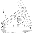
- Fig. 3 demonstrates the operating range of the mounting apparatus of Fig.1.
-
- Referring now to the drawings, in which like-referenced characters indicate corresponding elements throughout the several views, attention is first drawn to Figs. 1A and 1B which show a
terminal mounting apparatus 10 of the present invention.Terminal mounting apparatus 10 includesbase member 12,top member 14,pivot member 16 andconical clutch mechanism 18. -
Base member 12 includesbase plate 20 which has mountingapertures 22, such as those found on a standard telephone, for securingterminal mounting apparatus 10 on a vertical surface, such as a wall.Base plate 20 also has mountingpads 24 to enable the placement ofterminal mounting apparatus 10 on a horizontal surface without sliding or damaging the surface. -
Top member 14 includesterminal mounting plate 30, first top pivot member 32, and secondtop pivot member 38. First top pivot member 32 has first top pivot memberconical region 36, preferably of ABS-type plastic, preferably having a taper of about 60°.Top pivot members 32 and 38 connectterminal mounting plate 30 topivot member 16. First top pivot member 32 also hasnotches 34 for connecting first top pivot member 32 toconical clutch mechanism 18.Terminal mounting plate 30 contains the necessary attachments and venting for whatever device is selected to be mounted onterminal mounting apparatus 10. These necessary attachments are well-known and are beyond the scope of the present invention.Top pivot members 32 and 38 are detachable fromterminal mounting plate 30 so that various mounting plates can be used interminal mounting apparatus 10. -
Pivot member 16 includesshaft 50 withhandle 40,apertures cross pin 46, shaft retainer 54, andsupport washer 52. Handle 40 is located at one end ofshaft 50 and fits into the edge of first top pivot member 32 opposite first top pivot memberconical region 36. Shaft 50 hasaperture 44 forcross pin 46 to pass through, and screw 42 adjusts the position ofcross pin 46. Shaft 50 also hasaperture 48 for shaft retainer 54 to pass through. -
Clutch mechanism 18 includesplunger 62, foam spring pad 66, and floatingclutch plate 70. Plunger 62 contains a cam, andcross pin 46 rides incam groove 60. Plunger 62 has a conical region about its base, preferably having substantially the same taper as first top pivot memberconical region 36. Plunger 62 also haswings 64 extending beyond the conical region. Foam spring pad 66 nests againstplunger 62. Foam spring pad 66 has a conical shape, preferably having substantially the same degree of taper asplunger 62. Foam spring pad 66 is preferably rubber, however, other compressible materials may be substituted. Foam spring pad 66 nests against first top pivot memberconical region 36. Floatingclutch plate 70, preferably of nylon filled with talc, has taperedinner surface 74, preferably having substantially the same degree of taper as first top pivot memberconical region 36. First top pivot memberconical region 36 nests against floating clutch plate taperedinner surface 74. Floatingclutch plate 70 also hastabs 72 which secure floatingclutch plate 70 tobase plate 20. - In operation,
clutch mechanism 18 must be initially set (such as at the factory) to develop a predetermined frictional force between first top pivot memberconical region 36 and floating clutch plate taperedinner surface 74. Asshaft 50 turns, crosspin 46 rides incam groove 60 ofplunger 62. Rotation ofshaft 50 causes an axial motion ofplunger 62, and thus, the conical region ofplunger 62 compresses conical foam spring pad 66. Compressed foam spring pad 66 presses against first top pivot memberconical region 36. This pressure forces first top pivot memberconical region 36 against floating clutch plate taperedinner surface 74. Floatingclutch plate 70 cannot move axially since it is attached to, and pressed against,base plate 20. Shaft 50 is prevented from backing out by shaft retainer 54 andsupport washer 52. - The initial setting provides a predetermined frictional force between first top pivot member 32 and floating
clutch plate 70. This force, or resistance to rotation, must be overcome to adjust the tilt position oftop member 14 and also must be a sufficient force to maintaintop member 14 in any tilt position. Thus, first top pivot memberconical region 36 and floating clutch plate taperedinner surface 74 have a frictional fit. - In routine operation (after a predetermined frictional force has been established between first top pivot member 32 and floating clutch plate 70) when adjustment of the tilt position of
top member 14 is desired, a force must be applied totop member 14 causingpivot member 16 to rotate. To begin rotation ofpivot member 16, the force applied to tilttop member 14 must overcome the pre-existing frictional force (determined when initially settingclutch mechanism 18 as described above) between floating clutch plate taperedinner surface 74 and first top pivot memberconical region 36. Whenpivot member 16 is rotated, all parts ofclutch mechanism 18 rotate except floatingclutch plate 70.Pivot member 16 stops rotating when the force ontop member 14 is no longer large enough to overcome the frictional forces between first top pivot memberconical region 36 and floating clutch plate taperedinner surface 74. The frictional forces inclutch mechanism 18 maintainpivot member 16, and thustop member 14, in its last location. Maintainingpivot member 16 andtop member 14 at any location when the force is removed provides unlimited tilt positions. The frictional force is large enough to provide a stable surface even when, for example, a touch screen mounted ontop member 14 is operated. Although this description provides forclutch mechanism 18 to hold the position oftop member 14 on a rotating shaft,clutch mechanism 18 may be used to hold the position of any device on a rotating shaft. - Referring now to Figs. 2A and 2B, terminal 100 is shown secured to
top member 14 ofterminal mounting apparatus 10.Base member 12 ofterminal mounting apparatus 10 may be either vertical or horizontal. As shown in Fig. 2A, when vertical,base member 12 may be held by screws or other such mounting devices through mountingapertures 22 inbase member 12. As shown in Fig. 2B, when horizontal,base member 12 may rest on mountingpads 24. - In Fig. 3, the limits of the operating range are shown.
Top member 14 ofterminal mounting apparatus 10 can be adjusted to unlimited tilt positions within these limits, but obvious mechanical interference withbase member 12 prohibits tilt positions outside these limits. Thus, terminal 100 mounted ontop member 14 can be maintained at unlimited tilt positions within the limits shown. - Advantageously, mounting apparatus provides unlimited tilting in the operating range to increase operator comfort and reduce glare from ambient light.
Claims (5)
- A mounting apparatus comprising a base member (12), a top member (14), a pivot member (16) connecting the base member (12) and the top member (14), and a conical clutch mechanism (18) located around the pivot member (16) for adjusting and maintaining the tilt position of the top member (14) with respect to the base member (12), characterized in that the conical clutch mechanism (18) comprises a plunger (62) having a conical base, a cam groove (60) and a pair of wings (64) securing the plunger (62) to the top member (14), a conical foam spring pad (66) nesting to the conical base of the plunger (62), and a floating clutch plate (70) having a tapered inner surface, which has a friction fit with the top member (14), and also having tabs (72) for securing the floating clutch plate (70) to the base member (12).
- A mounting apparatus according to claim 1, characterised in that the pivot member (6) includes a cam (46) engaging with the cam groove (60) of the plunger (62), whereby movement of the cam in the cam groove (60) causes an axial force on the plunger (62) and the foam spring pad (66) to set the friction fit between the top member (14) and the floating clutch plate (70).
- A mounting apparatus according to claim 2, characterized in that the pivot member (16) comprises a shaft (50), a cross pin (46) extending through the shaft (50) constitutes the cam, and a shaft retainer (54) secures the shaft (50) to the base member (12).
- A conical clutch mechanism (18) for a device on a rotatable shaft (50), comprising a floating clutch plate (70) which has a conical region and which attaches to a non-rotating base member (12), and means for providing a friction fit between the device on the rotatable shaft (50) and the floating clutch plate (70), characterized in that said means for providing the friction fit comprises a plunger (62) having a conical base and a cam groove (60), a conical foam spring pad (66) nesting to the conical base of the plunger (62), and a cam (46) attached to the rotatable shaft (50) and engaging with the cam groove on the plunger, whereby movement of the cam in the cam groove (60) causes an axial force on the plunger (62) and the foam spring pad (66) to set the friction fit between the device on the rotatable shaft (50) and the floating clutch plate (70).
- A conical clutch mechanism according to claim 4, characterized in that the cam comprises a cross pin (46) extending through the shaft.
Applications Claiming Priority (2)
| Application Number | Priority Date | Filing Date | Title |
|---|---|---|---|
| US371636 | 1982-04-21 | ||
| US08/371,636 US5593119A (en) | 1995-01-12 | 1995-01-12 | Apparatus and method for mounting a terminal |
Publications (2)
| Publication Number | Publication Date |
|---|---|
| EP0722064A1 EP0722064A1 (en) | 1996-07-17 |
| EP0722064B1 true EP0722064B1 (en) | 2001-06-13 |
Family
ID=23464798
Family Applications (1)
| Application Number | Title | Priority Date | Filing Date |
|---|---|---|---|
| EP96300181A Expired - Lifetime EP0722064B1 (en) | 1995-01-12 | 1996-01-10 | A mounting apparatus |
Country Status (4)
| Country | Link |
|---|---|
| US (1) | US5593119A (en) |
| EP (1) | EP0722064B1 (en) |
| JP (1) | JPH08261248A (en) |
| DE (1) | DE69613247T2 (en) |
Families Citing this family (8)
| Publication number | Priority date | Publication date | Assignee | Title |
|---|---|---|---|---|
| US5887837A (en) * | 1996-09-30 | 1999-03-30 | Johns; H. Douglas | Pivotal computer stand |
| JPH10220491A (en) * | 1997-01-31 | 1998-08-21 | Three H:Kk | Overload control mechanism of cargo handling equipment |
| NZ333399A (en) * | 1997-12-24 | 2000-05-26 | Sankyo Co | Cyclooxygenase-2 inhibitors (COX-2) for the prevention and treatment of tumors, cachexia and tumor-metastasis |
| TW553576U (en) * | 2002-04-18 | 2003-09-11 | Quanta Comp Inc | Flat panel display and the folded base thereof |
| JP4143582B2 (en) * | 2004-08-26 | 2008-09-03 | Necディスプレイソリューションズ株式会社 | projector |
| US8480050B2 (en) * | 2010-04-15 | 2013-07-09 | Hubbell Incorporated | Multi-position base assembly for tool |
| CN105156849B (en) * | 2015-10-12 | 2017-09-22 | 奥林巴斯(北京)销售服务有限公司 | Rotating mechanism and display holding meanss |
| CN110319324B (en) * | 2018-03-30 | 2021-04-20 | 比亚迪股份有限公司 | Rotating mechanism for display terminal and vehicle having the same |
Family Cites Families (15)
| Publication number | Priority date | Publication date | Assignee | Title |
|---|---|---|---|---|
| US365413A (en) * | 1887-06-28 | Thill-coupling | ||
| US984523A (en) * | 1910-11-19 | 1911-02-21 | William Baer | Clutch mechanism. |
| US3692161A (en) * | 1970-10-14 | 1972-09-19 | Us Army | Self-locking clutch |
| DE2152256A1 (en) * | 1971-10-20 | 1973-05-03 | Demag Ag | CONE FRICTION BRAKE |
| US4834329A (en) * | 1987-05-29 | 1989-05-30 | Michael Delapp | Monitor support for a terminal |
| US4919387A (en) * | 1989-03-06 | 1990-04-24 | Bell & Howell Publication Systems Company | Tilt and swivel support apparatus |
| FR2645325B1 (en) * | 1989-03-31 | 1991-06-21 | Telemecanique Electrique | PORTABLE INFORMATION PROCESSING APPARATUS WITH ORIENTABLE SCREEN |
| US5016849A (en) * | 1989-11-17 | 1991-05-21 | Datatech Enterprises Co., Ltd. | Swivel mechanism for a monitor of a laptop computer |
| US4989813A (en) * | 1989-11-29 | 1991-02-05 | Samsung Electron Devices Co., Ltd. | Supporting base for controlling height, swivel and inclination of display means |
| US5075929A (en) * | 1990-07-02 | 1991-12-31 | Industrial Technology Research Institute | Hinge mechanism for a portable apparatus |
| US5108062A (en) * | 1990-09-28 | 1992-04-28 | Ncr Corporation | Pivot apparatus |
| US5022778A (en) * | 1990-11-02 | 1991-06-11 | Lu Sheng N | Pivot shaft |
| US5203434A (en) * | 1991-06-21 | 1993-04-20 | Dana Corporation | Mounting structure for cone brake |
| JPH05307425A (en) * | 1992-04-28 | 1993-11-19 | Brother Ind Ltd | Display unit supporting device |
| US5249103A (en) * | 1992-07-02 | 1993-09-28 | Ncr Corporation | Modular transaction terminal having a docking surface with a plurality of parallel grooves |
-
1995
- 1995-01-12 US US08/371,636 patent/US5593119A/en not_active Expired - Fee Related
-
1996
- 1996-01-10 EP EP96300181A patent/EP0722064B1/en not_active Expired - Lifetime
- 1996-01-10 DE DE69613247T patent/DE69613247T2/en not_active Expired - Lifetime
- 1996-01-12 JP JP8003734A patent/JPH08261248A/en active Pending
Also Published As
| Publication number | Publication date |
|---|---|
| JPH08261248A (en) | 1996-10-08 |
| DE69613247T2 (en) | 2002-04-18 |
| US5593119A (en) | 1997-01-14 |
| EP0722064A1 (en) | 1996-07-17 |
| DE69613247D1 (en) | 2001-07-26 |
Similar Documents
| Publication | Publication Date | Title |
|---|---|---|
| US6101676A (en) | Adjustable clutch hinge assembly for portable computer | |
| US5970819A (en) | Operating device of opening-closing body | |
| US5154382A (en) | Angle adjusting mechanism | |
| JP2002031469A (en) | Structure for installing display in refrigerator | |
| US4681413A (en) | Headband with optical device adjustably coupled thereto | |
| US5564669A (en) | Base support of a display device capable of moving on a surface | |
| US4733618A (en) | Apparatus for supporting equipment on an elevated surface | |
| CN111911751B (en) | camera mount | |
| US5593119A (en) | Apparatus and method for mounting a terminal | |
| JP2002339948A (en) | Turntable device | |
| US5590149A (en) | Mirror mount | |
| US5986645A (en) | Joystick with improved actuator | |
| JP2000105412A (en) | TV camera adjustment device | |
| EP0574125A1 (en) | Supporting device | |
| JP2006003737A (en) | Display support device | |
| US7789367B2 (en) | Tilt angle adjusting device with a shaft and a moment transmission member, and projector including the device | |
| CN210401636U (en) | Self-damping rotating device for magnetic resonance coil and head coil assembly | |
| KR100443870B1 (en) | Hinge assembly for flat panel display appliance | |
| US5533460A (en) | Thread tension device with latch for a sewing machine | |
| US5887693A (en) | Adjusting device for controlling switch | |
| JP4502695B2 (en) | Support device for electronic equipment | |
| KR100443869B1 (en) | Hinge assembly for flat panel display appliance | |
| CN223953687U (en) | Installation equipment and projection devices | |
| JPS63303298A (en) | Camera supporter | |
| KR100489787B1 (en) | Hinge assembly for flat panel display appliance |
Legal Events
| Date | Code | Title | Description |
|---|---|---|---|
| PUAI | Public reference made under article 153(3) epc to a published international application that has entered the european phase |
Free format text: ORIGINAL CODE: 0009012 |
|
| AK | Designated contracting states |
Kind code of ref document: A1 Designated state(s): DE FR GB |
|
| 17P | Request for examination filed |
Effective date: 19970117 |
|
| 17Q | First examination report despatched |
Effective date: 19990503 |
|
| GRAG | Despatch of communication of intention to grant |
Free format text: ORIGINAL CODE: EPIDOS AGRA |
|
| GRAG | Despatch of communication of intention to grant |
Free format text: ORIGINAL CODE: EPIDOS AGRA |
|
| GRAH | Despatch of communication of intention to grant a patent |
Free format text: ORIGINAL CODE: EPIDOS IGRA |
|
| GRAH | Despatch of communication of intention to grant a patent |
Free format text: ORIGINAL CODE: EPIDOS IGRA |
|
| GRAA | (expected) grant |
Free format text: ORIGINAL CODE: 0009210 |
|
| AK | Designated contracting states |
Kind code of ref document: B1 Designated state(s): DE FR GB |
|
| REF | Corresponds to: |
Ref document number: 69613247 Country of ref document: DE Date of ref document: 20010726 |
|
| ET | Fr: translation filed | ||
| REG | Reference to a national code |
Ref country code: GB Ref legal event code: IF02 |
|
| PLBE | No opposition filed within time limit |
Free format text: ORIGINAL CODE: 0009261 |
|
| STAA | Information on the status of an ep patent application or granted ep patent |
Free format text: STATUS: NO OPPOSITION FILED WITHIN TIME LIMIT |
|
| 26N | No opposition filed | ||
| REG | Reference to a national code |
Ref country code: GB Ref legal event code: 746 Effective date: 20030114 |
|
| REG | Reference to a national code |
Ref country code: FR Ref legal event code: D6 |
|
| PGFP | Annual fee paid to national office [announced via postgrant information from national office to epo] |
Ref country code: FR Payment date: 20100210 Year of fee payment: 15 |
|
| PGFP | Annual fee paid to national office [announced via postgrant information from national office to epo] |
Ref country code: GB Payment date: 20100201 Year of fee payment: 15 Ref country code: DE Payment date: 20100226 Year of fee payment: 15 |
|
| GBPC | Gb: european patent ceased through non-payment of renewal fee |
Effective date: 20110110 |
|
| REG | Reference to a national code |
Ref country code: FR Ref legal event code: ST Effective date: 20110930 |
|
| PG25 | Lapsed in a contracting state [announced via postgrant information from national office to epo] |
Ref country code: FR Free format text: LAPSE BECAUSE OF NON-PAYMENT OF DUE FEES Effective date: 20110131 |
|
| PG25 | Lapsed in a contracting state [announced via postgrant information from national office to epo] |
Ref country code: GB Free format text: LAPSE BECAUSE OF NON-PAYMENT OF DUE FEES Effective date: 20110110 |
|
| REG | Reference to a national code |
Ref country code: DE Ref legal event code: R119 Ref document number: 69613247 Country of ref document: DE Effective date: 20110802 |
|
| PG25 | Lapsed in a contracting state [announced via postgrant information from national office to epo] |
Ref country code: DE Free format text: LAPSE BECAUSE OF NON-PAYMENT OF DUE FEES Effective date: 20110802 |