EP0722043A1 - Compressed-air supply system for vehicles - Google Patents
Compressed-air supply system for vehicles Download PDFInfo
- Publication number
- EP0722043A1 EP0722043A1 EP95118067A EP95118067A EP0722043A1 EP 0722043 A1 EP0722043 A1 EP 0722043A1 EP 95118067 A EP95118067 A EP 95118067A EP 95118067 A EP95118067 A EP 95118067A EP 0722043 A1 EP0722043 A1 EP 0722043A1
- Authority
- EP
- European Patent Office
- Prior art keywords
- air
- foregoing
- compressed
- supply system
- air intake
- Prior art date
- Legal status (The legal status is an assumption and is not a legal conclusion. Google has not performed a legal analysis and makes no representation as to the accuracy of the status listed.)
- Granted
Links
- 230000005540 biological transmission Effects 0.000 claims abstract description 14
- 230000001105 regulatory effect Effects 0.000 claims description 2
- 238000002485 combustion reaction Methods 0.000 description 12
- 239000000446 fuel Substances 0.000 description 5
- 238000007689 inspection Methods 0.000 description 5
- 238000012423 maintenance Methods 0.000 description 4
- 239000000203 mixture Substances 0.000 description 4
- 238000001514 detection method Methods 0.000 description 3
- 230000001419 dependent effect Effects 0.000 description 2
- 239000007789 gas Substances 0.000 description 2
- 238000011144 upstream manufacturing Methods 0.000 description 2
- 238000003491 array Methods 0.000 description 1
- 230000001174 ascending effect Effects 0.000 description 1
- 230000009286 beneficial effect Effects 0.000 description 1
- 230000006835 compression Effects 0.000 description 1
- 238000007906 compression Methods 0.000 description 1
- 230000003467 diminishing effect Effects 0.000 description 1
- 238000000034 method Methods 0.000 description 1
Images

Classifications
-
- F—MECHANICAL ENGINEERING; LIGHTING; HEATING; WEAPONS; BLASTING
- F01—MACHINES OR ENGINES IN GENERAL; ENGINE PLANTS IN GENERAL; STEAM ENGINES
- F01L—CYCLICALLY OPERATING VALVES FOR MACHINES OR ENGINES
- F01L1/00—Valve-gear or valve arrangements, e.g. lift-valve gear
- F01L1/46—Component parts, details, or accessories, not provided for in preceding subgroups
- F01L1/462—Valve return spring arrangements
- F01L1/465—Pneumatic arrangements
-
- F—MECHANICAL ENGINEERING; LIGHTING; HEATING; WEAPONS; BLASTING
- F02—COMBUSTION ENGINES; HOT-GAS OR COMBUSTION-PRODUCT ENGINE PLANTS
- F02B—INTERNAL-COMBUSTION PISTON ENGINES; COMBUSTION ENGINES IN GENERAL
- F02B67/00—Engines characterised by the arrangement of auxiliary apparatus not being otherwise provided for, e.g. the apparatus having different functions; Driving auxiliary apparatus from engines, not otherwise provided for
- F02B67/04—Engines characterised by the arrangement of auxiliary apparatus not being otherwise provided for, e.g. the apparatus having different functions; Driving auxiliary apparatus from engines, not otherwise provided for of mechanically-driven auxiliary apparatus
-
- F—MECHANICAL ENGINEERING; LIGHTING; HEATING; WEAPONS; BLASTING
- F02—COMBUSTION ENGINES; HOT-GAS OR COMBUSTION-PRODUCT ENGINE PLANTS
- F02F—CYLINDERS, PISTONS OR CASINGS, FOR COMBUSTION ENGINES; ARRANGEMENTS OF SEALINGS IN COMBUSTION ENGINES
- F02F7/00—Casings, e.g. crankcases
- F02F7/006—Camshaft or pushrod housings
Definitions
- This invention concerns a compressed-air supply system for vehicles in which an engine-driven compressor in a vehicle provides compressed air to a variety of component pans of that vehicle, especially to a compressed-air supply system according to the preamble of claim 1.
- the drive transmission system conventionally used for vehicles such as automobiles and motorcycles is configured as follows.
- a transmission device comprised of a group of gears links the engines to the drive wheels.
- the above described transmission devices change the engagement of the group of gears in order to change the gear ratio to obtain the desired speed.
- the above described engines are fitted with intake and exhaust valves that open and close the intake and exhaust openings of the intake and exhaust passages into the combustion chamber, and these valves are held in the normally closed position over the foregoing intake and exhaust valves by pneumatic springs.
- intake and exhaust camshafts which are linked to the crankshaft of the foregoing engines which provide the cam system for the foregoing intake and exhaust valves. Then, when the engine is running, the foregoing intake and exhaust camshafts that are linked to the crankshaft overcome the force of the foregoing pneumatic springs by means of their cam system to appropriately open these valves.
- these pneumatic springs Through the repeated operation and use of these pneumatic springs, the air stored in their air chambers can gradually leak out, and conventionally a compressed-air cylinder is installed to replenish the compressed air in the foregoing air chambers.
- the problem with the requirement to install a compressed-air cylinder to replenish the compressed air in the air chambers of the pneumatic springs is that the compressed-air cylinder must be checked periodically for remaining air. When little air remains in the cylinder, it must be replaced with a new one, and such procedures complicate the maintenance and inspection of the foregoing pneumatic springs.
- An additional aspect is to simplify the maintenance and inspection on the pneumatic springs for the air intake and exhaust valves.
- the compressed-air supply system for vehicles of this invention comprises an air compressor driven by an engine, having at least one air intake valve and at least one exhaust valve operated by at least one camshaft, and an air pipe connected to said air compressor for supplying compressed air, whereby a first actuator is provided communicating with said pipe being capable of generating an operational force based upon the compressed air to assist the shifting operation of a transmission device.
- At least one air intake valve and said at least one exhaust valve are provided with pneumatic springs to hold said valves in a normally closed position and that a first regulator is provided communication with said pipe for regulating the air pressure in air chambers of said respective pneumatic springs.
- An air compressor is driven by the engine and supplies compressed air and that compressed air is fed to the actuators ,which are capable of delivering an operational force based on that supply of compressed air
- the compressed air from the air compressor that is driven by the engine is also supplied to the pneumatic springs which exert a force on the intake and exhaust valves , there is no need to mount a compressed-air cylinder to supply the compressed air to the pneumatic springs , as it was in the prior art, thereby eliminating the need for inspection of the compressed-air cylinder for remaining compressed air, and for its replacement when empty.
- 1 represents a four-cycle, in-line, four cylinder internal combustion engine mounted in a vehicle such as an automobile.
- the arrow labeled “Fr” in the figures points toward the front, and references to "left” or “right” shall be based upon facing forward in the foregoing direction.
- Each of these cylinders 2 is formed vertically into the cylinder block 4 and its axis 3 is parallel to the others.
- the cylinder bores 5 are formed into said cylinder block 4 along the above cylinder axes 3, a cylinder head 6 is mounted to the upward projecting end of the foregoing cylinder block 4, and a head cover 7 covers the top surface of this cylinder head 6.
- a number of fasteners removably hold the foregoing cylinder head 6 to the cylinder block 4.
- Pistons 10 have been inserted into the foregoing cylinder bores 5 and are free to slide up and down along the above mentioned cylindrical axes 3.
- the foregoing pistons 10 are linked to the crankshaft which is supported in the above mentioned crankcase by connecting rods 11.
- the spaces bounded by the foregoing cylinder block 4, cylinder head 6 and pistons 10 on the cylinder head 6 side comprise the combustion chambers 12.
- An air intake passage 14 extends from the back of the foregoing cylinder head 6 toward the front.
- a throttle valve mounted inside the air intake pipe 15 comprising the air intake pipe 14, a carburettor, and an air cleaner.
- On the downstream end of the foregoing air intake passage 14 are a plurality of double branches of which the ends, when viewed from the direction along the axes 3 of the cylinders 2 (a top view), open into the rear of the foregoing combustion chambers 12, wherein these various openings comprise the air intake openings 16.
- Air intake valves 18 open and close the foregoing air intake openings 16. These air intake valves 18 are equipped with valve stems 19 which are supported on the foregoing cylinder head 6 in a manner allowing them to freely slide up and down, and, integral valve bodies 20 are present at the lower end of the valve stems 19. Pneumatic springs 21 mounted on these valve bodies 20 exert a force to maintain the foregoing air intake valves 18 normally closed over the air intake openings 16 on the combustion chamber 21 side.
- the foregoing pneumatic springs 21 are equipped with a bowl-shaped lower member 21a which is attached to the foregoing cylinder head 6 and which opens upward, and a bowl-shaped upper member 21b that is linked to the foregoing valve stem 19 and which opens downward. Both the lower member 21a and upper member 21b are mounted with the valve stem 19 as their axial center, and they are fitted to be freely slidable in the axial direction. Tightly sealed air chambers 21c are formed in the space surrounded by the foregoing lower member 21a and upper member 21b, and compressed air 22 is supplied to the inside of these air chambers 21c. The expansion of the foregoing air chambers 21c caused by this compressed air 22 causes the foregoing upper member 21b to rise, and the valve stem 20 of the air intake valve 18 causes the air intake valve opening 16 to close as described above.
- a dynamic valve mechanism 23 is located in the space encompassed by the foregoing cylinder head 6 and the cylinder head cover 7.
- This dynamic valve system is equipped with an air intake camshaft 24 with an axis that extends left and right.
- This air intake camshaft 24 is supported by bearings 26 on the foregoing cylinder head 6 that allow it to rotate around its axis.
- These bearings 26 consist of bearing areas 26a which support the foregoing air intake camshaft 24 on the bottom, and of covers 26b which cover the top half from above of the same air intake camshaft 24. These covers 26b are fastened by fasteners 26c to the foregoing bearing areas 26a.
- the foregoing air intake camshaft 24 is linked to the aforementioned crankshaft causing it to rotate around its axis.
- the rotation of the foregoing air intake camshaft 24 around its axis causes the lifters 25 on the upper ends of the valve stems 19 to be engaged by the cams on the shaft, which, together with the force generated by the foregoing pneumatic springs 21, cause the foregoing air intake valves 18 to appropriately open and close the foregoing air intake valve openings 16.
- An exhaust passage 29 is present in the front of the foregoing cylinder head 6.
- the upstream end of this exhaust passage 29, when viewed along the axes 3 of the foregoing cylinders 2 (top view), comprises a plurality of double branches, and these branches open into the front side of the foregoing combustion chambers 12, wherein these various openings comprise the exhaust openings 30.
- the downstream end of the foregoing air intake passage 29 connects to the exhaust pipe 31.
- Exhaust valves 32 are set in the foregoing exhaust openings 30 which open and close them.
- the valve stems 33 of these exhaust valves 32 are supported on the foregoing cylinder head 6 to be freely slidable up and down.
- Valve bodies 34 are integral with the lower end of these valve stems 33.
- Pneumatic springs 35 exert a force on the foregoing exhaust valves 32 to normally close the valve bodies 34 over the foregoing exhaust openings 30 on the combustion chamber side 12.
- These pneumatic springs 35 evince the same structure as the foregoing pneumatic springs 21, and their air chambers 35c between the lower members 35a and upper members 35b cause them to function in the same way.
- the above mentioned dynamic valve mechanism 23 is further equipped with an exhaust camshaft 37 of which the axis extends left and right.
- Bearings 26 on the foregoing cylinder head 6 allow this exhaust camshaft 37 to rotate around its axis and are of the same structure as the bearings 26 described above.
- the foregoing exhaust camshaft 37 is linked to the above mentioned crankshaft, which causes it to rotate around its axis.
- the rotation around its axis by the foregoing exhaust camshaft 37 cause the lifters 38 on the tops of the foregoing valve stems 33 to be engaged by the cam system, which, along with the force generated by the foregoing pneumatic springs 35, cause the foregoing exhaust valves 32 to appropriately open and close the foregoing exhaust openings 30.
- variable valve timing device 40 is attached to the other end of the foregoing air intake camshaft 24.
- This variable valve timing device 40 and the right end of the foregoing exhaust camshaft 37 are linked by a chain mechanism 41.
- This chain mechanism 41 is composed of a drive sprocket 41a attached to the foregoing variable valve timing device 40, of a follower sprocket 41b that is attached to the right end of the foregoing exhaust camshaft 37, and of a chain 41c spanning the drive sprocket 41a and the follower sprocket 41b.
- the air intake camshaft 24 linked to the crankshaft as described above will rotate.
- the exhaust camshaft 37 is rotated by the foregoing variable valve timing device 40 on the air intake camshaft 24 and the chain mechanism 41.
- the exhaust camshaft 37 is indirectly driven by the foregoing crankshaft.
- the operation of the foregoing variable valve timing device 40 enables the rotational timing of the exhaust camshaft 37 to be varied with respect to the foregoing air intake camshaft 24. In other words, it makes it possible to vary the timing (crank angle) of the opening and closing operation of the exhaust valves 32 with respect to the opening and closing operation of the air intake valves 18.
- Spark plugs 43 are affixed in the foregoing cylinder head 6, and the discharge area of each spark plugs 43 is situated at the edge of each of the foregoing combustion chambers 12.
- An electronic control device 44 controls the foregoing engine 1, and this control device 44 is electrically connected with the foregoing spark plugs 43.
- the air intake valves 18 are opened to open the air intake openings 16.
- the negative pressure created in the cylinder bore 5 causes outside air to be drawn in through the air cleaner toward the carburetor, where fuel is mixed with the air to create an air/fuel mixture 45.
- the air fuel mixture 45 passes through the foregoing air intake pipe 15 and the air intake passage 14 and through the gap between the inside circumferential surface of the foregoing air intake openings 16 and the valve body 20 of the air intake valve 18 to enter the foregoing combustion chamber 12.
- the control device 44 causes the spark plug 43 to emit an electrical discharge that ignites the foregoing air/fuel mixture 45 and burns it during the power stroke, causing the foregoing piston 10 to descend and to convert the heat of combustion into motive force.
- this same piston 10 then begins ascending in the exhaust stroke, whereupon the gas generated by the foregoing combustion passes through the exhaust opening 30 which was opened by the operation of the exhaust valve 32, and then the gases are expelled from the cylinder 2 as exhaust through the exhaust passage 29, the exhaust pipe 31 and the muffler.
- the foregoing engine 1 is linked by a transmission device 48 composed of gear sets to the drive wheels.
- a transmission device 48 composed of gear sets to the drive wheels.
- an actuator 49 consisting of an air cylinder assists in the shifting operation.
- the total length of the air intake passage of the foregoing air intake passage 14 and air intake pipe 15 can be varied.
- the foregoing air intake pipe 15 consists of a sliding double-wall pipe, and an actuator 50 in the form of an air cylinder is used to change the length of this air intake pipe 15.
- Compressed air 22 is delivered from a reciprocating type of air compressor 52 that is driven by the foregoing engine 1.
- This air compressor 52 is removably attached to the top of the cylinder head cover 7 by bolts 53.
- a disc shaped support plate 55 is attached by a bolt 54 to the right end of the foregoing exhaust camshaft 34, and the end of a piston rod 56 of the foregoing air compressor 52 is axially supported by a shaft 57 on the foregoing support plate 55, wherein said shaft 57 is mounted to be eccentric with respect to the axis 58 of the exhaust camshaft 37.
- the outlet of the foregoing air compressor 52 is connected to the foregoing actuator 49 through a regulator 61 and a valve 62, and an actuator 63 such as a magnetic valve, opens and closes the foregoing valve 62 and is electrically connected to the foregoing control device 44.
- the outlet of the foregoing air compressor 52 is connected to the foregoing actuator 50 through the foregoing air pipe 60, an accumulator 65, regulator 66 and valve 67.
- An actuator 68 such as a magnetic valve, opens and closes the foregoing valve 67, and is electrically connected to the foregoing control device 44.
- a gear position sensor 70 is mounted on the foregoing transmission device 46 and detects whether or not the gear arrays are engaged (the gear position). This gear position sensor 70 is also electrically connected with the foregoing control device 44. Then, when changing the foregoing transmission device 48 to the desired gear ratio, the gear position sensor 70 detects the shifting operation, and that detection signal is fed into the foregoing control device 44. Thereupon, the control device 44 causes the actuator 63 to operate, whereby the valve 62 is opened and compressed air 22 is fed to the foregoing actuator 49. Next this compressed air 22 causes the foregoing actuator 49 to deliver an operational force to assist in the shifting of the foregoing transmission device 48.
- An operating-condition sensor 71 detects the operating condition of the engine 1 by detecting the RPM, etc, and this operating-condition sensor 71 is also electrically connected to the foregoing control device 44.
- the control device 44 When the control device 44 has received the detection signal from the foregoing operating condition detection sensor 71, it will drive the actuator 68 to appropriately adjust the valve 67 so that compressed air 22 is fed to the foregoing actuator 50.
- This compressed air 22 causes the foregoing actuator 50 to deliver an operational force, which adjusts the length of the foregoing air intake pipe 15. In other words, it is possible to adjust the length of the air intake pipe 15 without any operational force being supplied by the vehicle operator, and this action generates an air intake pulse that is beneficial in improving engine performance.
- the outlet of the foregoing air compressor 52 is also connected to each of the air chambers 21c, 35c of each above described pneumatic spring 21, 25 through the regulator 73, valve 74 and an air passage 75 in the cylinder head 6 to supply said chambers 21c, 35c with compressed air 22.
- the continuous supply of compressed air 22 maintains these pneumatic springs at their normal pressure, thereby assuring that they generate the required force.
- the air compressor 52 may equally well be driven by the air intake camshaft 24, or directly by the crankshaft.
- the present invention links an air compressor to the engine in order to deliver compressed air, and provides actuators generating operational forces based upon the supply of the foregoing compressed air.
- the operational force delivered by the foregoing actuators can be used to replace the operational force delivered by the vehicle operator or to lighten the force required of the operator thereby diminishing the operational stress on the operator of an operating vehicle.
- the compressor driven by the foregoing engine can also be used to provide compressed air to pneumatic springs exerting a force on the intake and exhaust valves, thereby eliminating the need to use a compressed-air cylinder as in the prior art to supply the pneumatic springs with compressed air, thereby eliminating the need to check such air cylinders for remaining air or to replace them when empty. This simplifies the inspection and maintenance of the pneumatic springs.
- any leakage from them is replenished, while only requiring a very small amount of air. Accordingly, by additionally supplying compressed air to the springs as well as to the foregoing actuators, the foregoing actuators are able to deliver the desired operational force. To wit, not only is the load on the vehicle operator lightened by using the foregoing actuators, but the maintenance and inspection of the pneumatic springs are also simplified.
Landscapes
- Engineering & Computer Science (AREA)
- Mechanical Engineering (AREA)
- General Engineering & Computer Science (AREA)
- Chemical & Material Sciences (AREA)
- Combustion & Propulsion (AREA)
- Valve-Gear Or Valve Arrangements (AREA)
- Valve Device For Special Equipments (AREA)
Abstract
Description
- This invention concerns a compressed-air supply system for vehicles in which an engine-driven compressor in a vehicle provides compressed air to a variety of component pans of that vehicle, especially to a compressed-air supply system according to the preamble of claim 1.
- The drive transmission system conventionally used for vehicles such as automobiles and motorcycles is configured as follows.
- Engines are mounted in such vehicles and then a transmission device comprised of a group of gears links the engines to the drive wheels. The above described transmission devices change the engagement of the group of gears in order to change the gear ratio to obtain the desired speed.
- On the other hand, the above described engines are fitted with intake and exhaust valves that open and close the intake and exhaust openings of the intake and exhaust passages into the combustion chamber, and these valves are held in the normally closed position over the foregoing intake and exhaust valves by pneumatic springs. There are also intake and exhaust camshafts which are linked to the crankshaft of the foregoing engines which provide the cam system for the foregoing intake and exhaust valves. Then, when the engine is running, the foregoing intake and exhaust camshafts that are linked to the crankshaft overcome the force of the foregoing pneumatic springs by means of their cam system to appropriately open these valves. Through the repeated operation and use of these pneumatic springs, the air stored in their air chambers can gradually leak out, and conventionally a compressed-air cylinder is installed to replenish the compressed air in the foregoing air chambers.
- However, the above described conventional structure incurs the following problems.
- First, when the gear sets in the transmission device are tightly engaged, a considerable amount of effort is required to change the engagement of the gears in the transmission, and a stress on the operator of the vehicle ensues.
- Second, the problem with the requirement to install a compressed-air cylinder to replenish the compressed air in the air chambers of the pneumatic springs is that the compressed-air cylinder must be checked periodically for remaining air. When little air remains in the cylinder, it must be replaced with a new one, and such procedures complicate the maintenance and inspection of the foregoing pneumatic springs.
- Accordingly, it is an objective of the present invention to provide an improved compressed-air supply system for vehicles as indicated above which is capable to lighten the operational load on an operator changing the engagement of the gears in the transmission.
- An additional aspect is to simplify the maintenance and inspection on the pneumatic springs for the air intake and exhaust valves.
- In order to attain the foregoing objective , the compressed-air supply system for vehicles of this invention comprises an air compressor driven by an engine, having at least one air intake valve and at least one exhaust valve operated by at least one camshaft, and an air pipe connected to said air compressor for supplying compressed air, whereby a first actuator is provided communicating with said pipe being capable of generating an operational force based upon the compressed air to assist the shifting operation of a transmission device.
- According to a preferred embodiment at least one air intake valve and said at least one exhaust valve are provided with pneumatic springs to hold said valves in a normally closed position and that a first regulator is provided communication with said pipe for regulating the air pressure in air chambers of said respective pneumatic springs. Further advantageous embodiments are laid down in the further dependent claims.
- The operation of one preferred embodiment is as follows.
- An air compressor is driven by the engine and supplies compressed air and that compressed air is fed to the actuators ,which are capable of delivering an operational force based on that supply of compressed air
- Also, because the compressed air from the air compressor that is driven by the engine is also supplied to the pneumatic springs which exert a force on the intake and exhaust valves , there is no need to mount a compressed-air cylinder to supply the compressed air to the pneumatic springs , as it was in the prior art, thereby eliminating the need for inspection of the compressed-air cylinder for remaining compressed air, and for its replacement when empty.
- Other preferred embodiments of the present invention are laid down in further dependent claims.
- In the following, the present invention is explained in greater detail with respect to several embodiments thereof in conjunction with the accompanying drawings, wherein:
- Figure 1 is a sectional top view along line 1-1 of Figure 2.
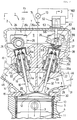
- Figure 2 is a sectional side view of the engine.
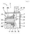
- Figure 3 is a sectional view along line 3-3 of Figure 2.
- In the Figures, 1 represents a four-cycle, in-line, four cylinder internal combustion engine mounted in a vehicle such as an automobile. To facilitate the description, the arrow labeled "Fr" in the figures points toward the front, and references to "left" or "right" shall be based upon facing forward in the foregoing direction.
- Four
cylinders 2, left and right, project upward from the crankcase of the foregoing engine 1. Each of thesecylinders 2 is formed vertically into the cylinder block 4 and itsaxis 3 is parallel to the others. Thecylinder bores 5 are formed into said cylinder block 4 along theabove cylinder axes 3, acylinder head 6 is mounted to the upward projecting end of the foregoing cylinder block 4, and ahead cover 7 covers the top surface of thiscylinder head 6. A number of fasteners removably hold the foregoingcylinder head 6 to the cylinder block 4. - Pistons 10 have been inserted into the foregoing
cylinder bores 5 and are free to slide up and down along the above mentionedcylindrical axes 3. Theforegoing pistons 10 are linked to the crankshaft which is supported in the above mentioned crankcase by connectingrods 11. The spaces bounded by the foregoing cylinder block 4,cylinder head 6 andpistons 10 on thecylinder head 6 side comprise thecombustion chambers 12. - An
air intake passage 14 extends from the back of theforegoing cylinder head 6 toward the front. On the upstream side of thisair intake passage 14 are a throttle valve, mounted inside theair intake pipe 15 comprising theair intake pipe 14, a carburettor, and an air cleaner. On the downstream end of the foregoingair intake passage 14 are a plurality of double branches of which the ends, when viewed from the direction along theaxes 3 of the cylinders 2 (a top view), open into the rear of theforegoing combustion chambers 12, wherein these various openings comprise theair intake openings 16. -
Air intake valves 18 open and close the foregoingair intake openings 16. Theseair intake valves 18 are equipped withvalve stems 19 which are supported on the foregoingcylinder head 6 in a manner allowing them to freely slide up and down, and,integral valve bodies 20 are present at the lower end of thevalve stems 19.Pneumatic springs 21 mounted on thesevalve bodies 20 exert a force to maintain the foregoingair intake valves 18 normally closed over theair intake openings 16 on thecombustion chamber 21 side. - The foregoing
pneumatic springs 21 are equipped with a bowl-shapedlower member 21a which is attached to the foregoingcylinder head 6 and which opens upward, and a bowl-shaped upper member 21b that is linked to the foregoingvalve stem 19 and which opens downward. Both thelower member 21a and upper member 21b are mounted with thevalve stem 19 as their axial center, and they are fitted to be freely slidable in the axial direction. Tightly sealedair chambers 21c are formed in the space surrounded by the foregoinglower member 21a and upper member 21b, and compressedair 22 is supplied to the inside of theseair chambers 21c. The expansion of theforegoing air chambers 21c caused by thiscompressed air 22 causes the foregoing upper member 21b to rise, and thevalve stem 20 of theair intake valve 18 causes the air intake valve opening 16 to close as described above. - In addition, a
dynamic valve mechanism 23 is located in the space encompassed by the foregoingcylinder head 6 and thecylinder head cover 7. This dynamic valve system is equipped with anair intake camshaft 24 with an axis that extends left and right. Thisair intake camshaft 24 is supported bybearings 26 on the foregoingcylinder head 6 that allow it to rotate around its axis. Thesebearings 26 consist of bearingareas 26a which support the foregoingair intake camshaft 24 on the bottom, and of covers 26b which cover the top half from above of the sameair intake camshaft 24. Thesecovers 26b are fastened byfasteners 26c to the foregoing bearingareas 26a. - The foregoing
air intake camshaft 24 is linked to the aforementioned crankshaft causing it to rotate around its axis. The rotation of the foregoingair intake camshaft 24 around its axis causes thelifters 25 on the upper ends of the valve stems 19 to be engaged by the cams on the shaft, which, together with the force generated by the foregoingpneumatic springs 21, cause the foregoingair intake valves 18 to appropriately open and close the foregoing airintake valve openings 16. - An
exhaust passage 29 is present in the front of the foregoingcylinder head 6. The upstream end of thisexhaust passage 29, when viewed along theaxes 3 of the foregoing cylinders 2 (top view), comprises a plurality of double branches, and these branches open into the front side of theforegoing combustion chambers 12, wherein these various openings comprise theexhaust openings 30. The downstream end of the foregoingair intake passage 29 connects to theexhaust pipe 31. -
Exhaust valves 32 are set in the foregoingexhaust openings 30 which open and close them. The valve stems 33 of theseexhaust valves 32 are supported on the foregoingcylinder head 6 to be freely slidable up and down.Valve bodies 34 are integral with the lower end of thesevalve stems 33.Pneumatic springs 35 exert a force on the foregoingexhaust valves 32 to normally close thevalve bodies 34 over the foregoingexhaust openings 30 on thecombustion chamber side 12. Thesepneumatic springs 35 evince the same structure as the foregoingpneumatic springs 21, and theirair chambers 35c between thelower members 35a andupper members 35b cause them to function in the same way. - The above mentioned
dynamic valve mechanism 23 is further equipped with anexhaust camshaft 37 of which the axis extends left and right.Bearings 26 on the foregoingcylinder head 6 allow thisexhaust camshaft 37 to rotate around its axis and are of the same structure as thebearings 26 described above. - The
foregoing exhaust camshaft 37 is linked to the above mentioned crankshaft, which causes it to rotate around its axis. The rotation around its axis by theforegoing exhaust camshaft 37 cause thelifters 38 on the tops of the foregoing valve stems 33 to be engaged by the cam system, which, along with the force generated by the foregoingpneumatic springs 35, cause theforegoing exhaust valves 32 to appropriately open and close theforegoing exhaust openings 30. - In this configuration, the left end of the
air intake camshaft 24 is linked to the foregoing crankshaft by means of a timing belt mechanism. In addition, a variablevalve timing device 40 is attached to the other end of the foregoingair intake camshaft 24. This variablevalve timing device 40 and the right end of the foregoingexhaust camshaft 37 are linked by achain mechanism 41. Thischain mechanism 41 is composed of adrive sprocket 41a attached to the foregoing variablevalve timing device 40, of a follower sprocket 41b that is attached to the right end of the foregoingexhaust camshaft 37, and of achain 41c spanning thedrive sprocket 41a and the follower sprocket 41b. - When the engine 1 is started, the
air intake camshaft 24 linked to the crankshaft as described above will rotate. In addition, theexhaust camshaft 37 is rotated by the foregoing variablevalve timing device 40 on theair intake camshaft 24 and thechain mechanism 41. In other words, theexhaust camshaft 37 is indirectly driven by the foregoing crankshaft. The operation of the foregoing variablevalve timing device 40 enables the rotational timing of theexhaust camshaft 37 to be varied with respect to the foregoingair intake camshaft 24. In other words, it makes it possible to vary the timing (crank angle) of the opening and closing operation of theexhaust valves 32 with respect to the opening and closing operation of theair intake valves 18. - Spark plugs 43 are affixed in the foregoing
cylinder head 6, and the discharge area of each spark plugs 43 is situated at the edge of each of the foregoingcombustion chambers 12. Anelectronic control device 44 controls the foregoing engine 1, and thiscontrol device 44 is electrically connected with the foregoing spark plugs 43. - When the foregoing engine 1 is started, and a
piston 10 descends from its upper dead point to its lower dead point in the air intake stroke, theair intake valves 18 are opened to open theair intake openings 16. At this time, the negative pressure created in the cylinder bore 5, theair intake passage 14 and theair intake pipe 15 causes outside air to be drawn in through the air cleaner toward the carburetor, where fuel is mixed with the air to create an air/fuel mixture 45. Theair fuel mixture 45 passes through the foregoingair intake pipe 15 and theair intake passage 14 and through the gap between the inside circumferential surface of the foregoingair intake openings 16 and thevalve body 20 of theair intake valve 18 to enter the foregoingcombustion chamber 12. - When the foregoing
piston 10 reaches its lower dead point and begins its ascent for the compression stroke, and when the foregoingpiston 10 reaches the vicinity of its upper dead point, the foregoing air/fuel mixture 45 in thecombustion chamber 12 becomes adequately compressed. At this time, thecontrol device 44 causes thespark plug 43 to emit an electrical discharge that ignites the foregoing air/fuel mixture 45 and burns it during the power stroke, causing the foregoingpiston 10 to descend and to convert the heat of combustion into motive force. Continuing, thissame piston 10 then begins ascending in the exhaust stroke, whereupon the gas generated by the foregoing combustion passes through theexhaust opening 30 which was opened by the operation of theexhaust valve 32, and then the gases are expelled from thecylinder 2 as exhaust through theexhaust passage 29, theexhaust pipe 31 and the muffler. - Thereafter, the above described strokes are repeated, and the engine 1 delivers motive force.
- The foregoing engine 1 is linked by a
transmission device 48 composed of gear sets to the drive wheels. When the speed is changed for the foregoingtransmission device 48, anactuator 49 consisting of an air cylinder assists in the shifting operation. - In addition, the total length of the air intake passage of the foregoing
air intake passage 14 andair intake pipe 15 can be varied. Specifically, the foregoingair intake pipe 15 consists of a sliding double-wall pipe, and anactuator 50 in the form of an air cylinder is used to change the length of thisair intake pipe 15. -
Compressed air 22 is delivered from a reciprocating type ofair compressor 52 that is driven by the foregoing engine 1. Thisair compressor 52 is removably attached to the top of thecylinder head cover 7 bybolts 53. A disc shapedsupport plate 55 is attached by abolt 54 to the right end of the foregoingexhaust camshaft 34, and the end of apiston rod 56 of the foregoingair compressor 52 is axially supported by ashaft 57 on the foregoingsupport plate 55, wherein saidshaft 57 is mounted to be eccentric with respect to theaxis 58 of theexhaust camshaft 37. Then, when the engine 1 is started, theexhaust camshaft 37, which is driven by links to the crankshaft, causes the foregoingpiston rod 56 to move reciprocally, which drives theair compressor 52 to output compressedair 22 from thecompressor 52. - The outlet of the foregoing
air compressor 52 is connected to the foregoingactuator 49 through aregulator 61 and avalve 62, and anactuator 63 such as a magnetic valve, opens and closes the foregoingvalve 62 and is electrically connected to the foregoingcontrol device 44. In addition, the outlet of the foregoingair compressor 52 is connected to the foregoingactuator 50 through the foregoingair pipe 60, anaccumulator 65,regulator 66 andvalve 67. Anactuator 68, such as a magnetic valve, opens and closes the foregoingvalve 67, and is electrically connected to the foregoingcontrol device 44. - Also, a
gear position sensor 70 is mounted on the foregoing transmission device 46 and detects whether or not the gear arrays are engaged (the gear position). Thisgear position sensor 70 is also electrically connected with the foregoingcontrol device 44. Then, when changing the foregoingtransmission device 48 to the desired gear ratio, thegear position sensor 70 detects the shifting operation, and that detection signal is fed into the foregoingcontrol device 44. Thereupon, thecontrol device 44 causes theactuator 63 to operate, whereby thevalve 62 is opened andcompressed air 22 is fed to the foregoingactuator 49. Next thiscompressed air 22 causes the foregoingactuator 49 to deliver an operational force to assist in the shifting of the foregoingtransmission device 48. - An operating-
condition sensor 71 detects the operating condition of the engine 1 by detecting the RPM, etc, and this operating-condition sensor 71 is also electrically connected to the foregoingcontrol device 44. When thecontrol device 44 has received the detection signal from the foregoing operatingcondition detection sensor 71, it will drive theactuator 68 to appropriately adjust thevalve 67 so thatcompressed air 22 is fed to the foregoingactuator 50. Thiscompressed air 22 causes the foregoingactuator 50 to deliver an operational force, which adjusts the length of the foregoingair intake pipe 15. In other words, it is possible to adjust the length of theair intake pipe 15 without any operational force being supplied by the vehicle operator, and this action generates an air intake pulse that is beneficial in improving engine performance. - The outlet of the foregoing
air compressor 52 is also connected to each of theair chambers pneumatic spring regulator 73,valve 74 and anair passage 75 in thecylinder head 6 to supply saidchambers compressed air 22. Thus, should somecompressed air 22 leak out of the foregoing pneumatic springs 21, 35, the continuous supply ofcompressed air 22 maintains these pneumatic springs at their normal pressure, thereby assuring that they generate the required force. - In the embodiment shown in the figures, the
air compressor 52 may equally well be driven by theair intake camshaft 24, or directly by the crankshaft. - The present invention links an air compressor to the engine in order to deliver compressed air, and provides actuators generating operational forces based upon the supply of the foregoing compressed air.
- The operational force delivered by the foregoing actuators can be used to replace the operational force delivered by the vehicle operator or to lighten the force required of the operator thereby diminishing the operational stress on the operator of an operating vehicle.
- In addition, the compressor driven by the foregoing engine can also be used to provide compressed air to pneumatic springs exerting a force on the intake and exhaust valves, thereby eliminating the need to use a compressed-air cylinder as in the prior art to supply the pneumatic springs with compressed air, thereby eliminating the need to check such air cylinders for remaining air or to replace them when empty. This simplifies the inspection and maintenance of the pneumatic springs.
- Also, by providing this compressed air to the foregoing pneumatic springs, any leakage from them is replenished, while only requiring a very small amount of air. Accordingly, by additionally supplying compressed air to the springs as well as to the foregoing actuators, the foregoing actuators are able to deliver the desired operational force. To wit, not only is the load on the vehicle operator lightened by using the foregoing actuators, but the maintenance and inspection of the pneumatic springs are also simplified.
Claims (9)
- A compressed-air supply system for vehicles, comprising an air compressor (52) driven by an engine (1), having at least one air intake valve (18) and at least one exhaust valve (32) operated by at least one camshaft (24,37), and an air pipe (60) connected to said air compressor (52) for supplying compressed air (22), characterized in that a first actuator (49) is provided communicating with said pipe (60) being capable of generating an operational force based upon the compressed air (22) to assist the shifting operation of a transmission device (48).
- A compressed-air supply system according to claim 1, characterized in that said at least one air intake valve (18) and said at least one exhaust valve (32) are provided with pneumatic springs (21,35) to hold said valves (18,32) in a normally closed position and that a first regulator (73) is provided communicating with said pipe (60) for regulating the air pressure in air chambers (21c,35c) of said respective pneumatic springs (21,35).
- A compressed-air supply system according to claim 1 or 2, characterized in that a second actuator (50) is provided communicating with said pipe (60) being capable of generating an operational force based upon the compressed air (22) to control the length of an air intake passage (14,15).
- A compressed-air supply system according to at least one of the preceding claims 1 to 3, characterized in that a second regulator (61) is provided between said air-compressor (52) and said first actuator (49).
- A compressed-air supply system according to at least one of the preceding claims 2 to 4, characterized in that a valve (74), arranged between said first regulator (73) and said pneumatic springs (21,35), is operable by said first regulator (73).
- A compressed-air supply system according to at least one of the preceding claims 3 to 5, characterized in that a third regulator (66) is arranged between said air compressor (52) and said second actuator (50).
- A compressed-air supply system according to at least one of the preceding claims 1 to 6, characterized in that said air compressor (52) is driven by a crankshaft or by one of the at least one camshafts (24,37).
- A compressed-air supply system according to at least one of the preceding claims 1 to 6, characterized in that said engine (1) comprises an air intake camshaft (24) for operating said at least one air intake valve (18) and an exhaust camshaft (37) for operating said at least one exhaust valve (32) and that said air compressor (52) is driven by said exhaust camshaft (37).
- A compressed-air supply system according to claim 8, characterized in that one end of the air intake camshaft (24) is linked to the crankshaft through a timing belt mechanism and that the other end of said air intake camshaft (24) is provided with a variable valve timing device (40).
Applications Claiming Priority (3)
| Application Number | Priority Date | Filing Date | Title |
|---|---|---|---|
| JP308331/94 | 1994-11-16 | ||
| JP30833194 | 1994-11-16 | ||
| JP30833194A JP3145591B2 (en) | 1994-11-16 | 1994-11-16 | Vehicle compressed air supply system |
Publications (2)
| Publication Number | Publication Date |
|---|---|
| EP0722043A1 true EP0722043A1 (en) | 1996-07-17 |
| EP0722043B1 EP0722043B1 (en) | 2001-10-10 |
Family
ID=17979773
Family Applications (1)
| Application Number | Title | Priority Date | Filing Date |
|---|---|---|---|
| EP95118067A Expired - Lifetime EP0722043B1 (en) | 1994-11-16 | 1995-11-16 | Compressed-air supply system for vehicles |
Country Status (4)
| Country | Link |
|---|---|
| US (1) | US6083140A (en) |
| EP (1) | EP0722043B1 (en) |
| JP (1) | JP3145591B2 (en) |
| DE (1) | DE69523133T2 (en) |
Cited By (6)
| Publication number | Priority date | Publication date | Assignee | Title |
|---|---|---|---|---|
| EP0854271A1 (en) * | 1997-01-21 | 1998-07-22 | Daimler-Benz Aktiengesellschaft | Camshaft bearing arrangement in the cylinder head of an internal combustion engine |
| EP1242721A4 (en) * | 1999-12-30 | 2009-08-12 | Ecoforce Pty Ltd | Internal combustion engine with valve control |
| EP1843012A3 (en) * | 2002-12-21 | 2010-01-06 | Schaeffler KG | Combustion engine with a device for hydraulic rotation angle adjustment of the camshaft in relation to the crankshaft and a vacuum pump for a servo user, in particular for a braking power intensifier |
| EP2208871A1 (en) * | 2009-01-20 | 2010-07-21 | BRP-Powertrain GmbH & Co. KG | Internal combustion engine air spring system arrangement |
| EP2208870A1 (en) * | 2009-01-20 | 2010-07-21 | BRP-Powertrain GmbH & Co. KG | Air spring system for an internal combustion engine |
| EP2211031A1 (en) * | 2009-01-22 | 2010-07-28 | BRP-Powertrain GmbH & Co. KG | Air spring with cap |
Families Citing this family (9)
| Publication number | Priority date | Publication date | Assignee | Title |
|---|---|---|---|---|
| DE19956825C1 (en) * | 1999-11-25 | 2001-02-08 | Porsche Ag | Cylinder head for an IC motor has a head system with valves at the same angle for a variant with fuel intake and a variant for direct fuel injection as a common head for either type |
| US6716137B1 (en) | 2002-08-29 | 2004-04-06 | Ford Global Technologies, Llc | Method for controlling camless engine having an automatically controlled transmission |
| US6738702B2 (en) | 2002-08-29 | 2004-05-18 | Ford Global Technologies, Llc | Method for particulate filter regeneration in vehicles having an automatically controlled transmission |
| US6929582B2 (en) * | 2003-10-01 | 2005-08-16 | Ford Global Technologies, Llc | Method for controlling variable compression ratio of an engine having an automatically controlled transmission |
| JP4538279B2 (en) * | 2004-08-16 | 2010-09-08 | 本田技研工業株式会社 | Direct fuel injection internal combustion engine |
| JP2007192078A (en) * | 2006-01-18 | 2007-08-02 | Yamaha Motor Co Ltd | Engine and vehicle |
| JP4218715B2 (en) * | 2006-08-31 | 2009-02-04 | トヨタ自動車株式会社 | cylinder head |
| JP2009013801A (en) * | 2007-07-02 | 2009-01-22 | Kawasaki Heavy Ind Ltd | Motorcycle with valve mechanism |
| CN103061818B (en) * | 2011-10-18 | 2014-09-03 | 周登荣 | Compressed air power engine assembly with compressed air supplementary return circuit |
Citations (4)
| Publication number | Priority date | Publication date | Assignee | Title |
|---|---|---|---|---|
| US3771388A (en) * | 1970-12-21 | 1973-11-13 | Toyota Motor Co Ltd | Fluid control system for automatic vehicle transmissions |
| US4499793A (en) * | 1981-11-04 | 1985-02-19 | Transtech Industrial Corporation | Automatic gear shifting device |
| FR2627131A1 (en) * | 1988-02-13 | 1989-08-18 | Man Nutzfahrzeuge Gmbh | |
| FR2631078A1 (en) * | 1988-05-07 | 1989-11-10 | Man Nutzfahrzeuge Gmbh | AUXILIARY DEVICE FOR DRIVING ROTATION OF AN AIR COMPRESSOR COUPLED TO AN INTERNAL COMBUSTION ENGINE |
Family Cites Families (10)
| Publication number | Priority date | Publication date | Assignee | Title |
|---|---|---|---|---|
| DE2002470C2 (en) * | 1970-01-21 | 1982-09-09 | Daimler-Benz Ag, 7000 Stuttgart | Arrangement of an air compressor on an internal combustion engine |
| JPS61196825A (en) * | 1985-01-25 | 1986-09-01 | Honda Motor Co Ltd | Controller of accessories for vehicle driven by engine |
| US4612826A (en) * | 1985-02-13 | 1986-09-23 | Ford Motor Company | Transmission throttle valve modulator responsive to both positive manifold pressure and negative manifold pressure |
| HU198984B (en) * | 1986-10-27 | 1989-12-28 | Csepeli Autogyar | Arrangement for starting the engine of road motor vehicle by pushing |
| JP2593352B2 (en) * | 1989-04-26 | 1997-03-26 | 本田技研工業株式会社 | Valve train for internal combustion engine |
| US5216989A (en) * | 1990-11-30 | 1993-06-08 | Mazda Motor Corporation | Apparatus for driving various devices by internal combustion engine |
| DE4101672A1 (en) * | 1991-01-22 | 1992-07-23 | Zahnradfabrik Friedrichshafen | SHIFTING AND DRIVING RANGE SELECTION DEVICE FOR A SEMI- OR FULLY AUTOMATICALLY SWITCHABLE GEAR GEAR TRANSMISSION OF A MOTOR VEHICLE |
| US5233950A (en) * | 1991-08-21 | 1993-08-10 | Honda Giken Kogyo Kabushiki Kaisha | Valve operating system for internal combustion engine |
| US5515675A (en) * | 1994-11-23 | 1996-05-14 | Bindschatel; Lyle D. | Apparatus to convert a four-stroke internal combustion engine to a two-stroke pneumatically powered engine |
| US5529028A (en) * | 1995-06-07 | 1996-06-25 | Cummins Engine Company, Inc. | Accessory control system for a vehicle |
-
1994
- 1994-11-16 JP JP30833194A patent/JP3145591B2/en not_active Expired - Fee Related
-
1995
- 1995-11-15 US US08/558,163 patent/US6083140A/en not_active Expired - Fee Related
- 1995-11-16 DE DE69523133T patent/DE69523133T2/en not_active Expired - Fee Related
- 1995-11-16 EP EP95118067A patent/EP0722043B1/en not_active Expired - Lifetime
Patent Citations (4)
| Publication number | Priority date | Publication date | Assignee | Title |
|---|---|---|---|---|
| US3771388A (en) * | 1970-12-21 | 1973-11-13 | Toyota Motor Co Ltd | Fluid control system for automatic vehicle transmissions |
| US4499793A (en) * | 1981-11-04 | 1985-02-19 | Transtech Industrial Corporation | Automatic gear shifting device |
| FR2627131A1 (en) * | 1988-02-13 | 1989-08-18 | Man Nutzfahrzeuge Gmbh | |
| FR2631078A1 (en) * | 1988-05-07 | 1989-11-10 | Man Nutzfahrzeuge Gmbh | AUXILIARY DEVICE FOR DRIVING ROTATION OF AN AIR COMPRESSOR COUPLED TO AN INTERNAL COMBUSTION ENGINE |
Cited By (8)
| Publication number | Priority date | Publication date | Assignee | Title |
|---|---|---|---|---|
| EP0854271A1 (en) * | 1997-01-21 | 1998-07-22 | Daimler-Benz Aktiengesellschaft | Camshaft bearing arrangement in the cylinder head of an internal combustion engine |
| US5934235A (en) * | 1997-01-21 | 1999-08-10 | Astner; Josef | Camshaft support arrangement in the cylinder head of an internal combustion engine |
| EP1242721A4 (en) * | 1999-12-30 | 2009-08-12 | Ecoforce Pty Ltd | Internal combustion engine with valve control |
| EP1843012A3 (en) * | 2002-12-21 | 2010-01-06 | Schaeffler KG | Combustion engine with a device for hydraulic rotation angle adjustment of the camshaft in relation to the crankshaft and a vacuum pump for a servo user, in particular for a braking power intensifier |
| EP2208871A1 (en) * | 2009-01-20 | 2010-07-21 | BRP-Powertrain GmbH & Co. KG | Internal combustion engine air spring system arrangement |
| EP2208870A1 (en) * | 2009-01-20 | 2010-07-21 | BRP-Powertrain GmbH & Co. KG | Air spring system for an internal combustion engine |
| US8375903B2 (en) | 2009-01-20 | 2013-02-19 | Brp-Powertrain Gmbh & Co. Kg | Internal combustion engine air spring system arrangement |
| EP2211031A1 (en) * | 2009-01-22 | 2010-07-28 | BRP-Powertrain GmbH & Co. KG | Air spring with cap |
Also Published As
| Publication number | Publication date |
|---|---|
| US6083140A (en) | 2000-07-04 |
| JP3145591B2 (en) | 2001-03-12 |
| DE69523133T2 (en) | 2002-01-31 |
| EP0722043B1 (en) | 2001-10-10 |
| JPH08144772A (en) | 1996-06-04 |
| DE69523133D1 (en) | 2001-11-15 |
Similar Documents
| Publication | Publication Date | Title |
|---|---|---|
| EP0722043B1 (en) | Compressed-air supply system for vehicles | |
| JP4154622B2 (en) | Device for changing effective displacement and / or volume ratio during operation of a piston engine | |
| CN101054912B (en) | Cylinder deactivation apparatus | |
| US20020189592A1 (en) | Control system for engine | |
| JP5557964B2 (en) | 2-stroke pneumatic engine assembly | |
| US6286467B1 (en) | Two stroke engine conversion | |
| US5558049A (en) | Variable orbital aperture valve system for fluid processing machines | |
| CN111373124A (en) | Variable valve timing system of engine | |
| CN1244751C (en) | Internal combustion engine with valve control | |
| US6065440A (en) | Internal combustion engine with binary cylinder sizing for variable power output | |
| US6189498B1 (en) | Cam shaft drive for engine | |
| US6378483B1 (en) | Lubrication system for four-stroke engine | |
| EP0831214B1 (en) | Two-cycle internal combustion engine | |
| EP1470322B1 (en) | A crankcase scavenged four-stroke engine | |
| US6694942B1 (en) | Four-stroke engine with rotary valve control | |
| KR20000005309A (en) | Air and exhaust gas management system for a twocycle internal combustion engine | |
| EP0450509A1 (en) | Internal combustion engine with at least an exhaust port in the cylinder | |
| JP2006514208A (en) | 4-cycle engine | |
| EP0974743B1 (en) | Lubrication system of reciprocating piston type compressor for engine supercharging | |
| JP4602305B2 (en) | In-cylinder direct injection internal combustion engine | |
| WO2016145562A1 (en) | Increased duration intake camshaft with dwell at peak lift | |
| AU767801B2 (en) | Internal combustion engine with valve control | |
| CA2613170A1 (en) | Two-stroke internal combustion engine with enhanced scavenging | |
| KR20000067490A (en) | Hydraulic lash adjuster of valve for vehicle | |
| CA2352616A1 (en) | Two stroke engine conversion |
Legal Events
| Date | Code | Title | Description |
|---|---|---|---|
| PUAI | Public reference made under article 153(3) epc to a published international application that has entered the european phase |
Free format text: ORIGINAL CODE: 0009012 |
|
| AK | Designated contracting states |
Kind code of ref document: A1 Designated state(s): DE FR GB |
|
| 17P | Request for examination filed |
Effective date: 19970116 |
|
| 17Q | First examination report despatched |
Effective date: 19980824 |
|
| GRAG | Despatch of communication of intention to grant |
Free format text: ORIGINAL CODE: EPIDOS AGRA |
|
| GRAG | Despatch of communication of intention to grant |
Free format text: ORIGINAL CODE: EPIDOS AGRA |
|
| GRAH | Despatch of communication of intention to grant a patent |
Free format text: ORIGINAL CODE: EPIDOS IGRA |
|
| GRAH | Despatch of communication of intention to grant a patent |
Free format text: ORIGINAL CODE: EPIDOS IGRA |
|
| GRAH | Despatch of communication of intention to grant a patent |
Free format text: ORIGINAL CODE: EPIDOS IGRA |
|
| GRAH | Despatch of communication of intention to grant a patent |
Free format text: ORIGINAL CODE: EPIDOS IGRA |
|
| GRAA | (expected) grant |
Free format text: ORIGINAL CODE: 0009210 |
|
| AK | Designated contracting states |
Kind code of ref document: B1 Designated state(s): DE FR GB |
|
| REF | Corresponds to: |
Ref document number: 69523133 Country of ref document: DE Date of ref document: 20011115 |
|
| REG | Reference to a national code |
Ref country code: GB Ref legal event code: IF02 |
|
| ET | Fr: translation filed | ||
| PLBE | No opposition filed within time limit |
Free format text: ORIGINAL CODE: 0009261 |
|
| STAA | Information on the status of an ep patent application or granted ep patent |
Free format text: STATUS: NO OPPOSITION FILED WITHIN TIME LIMIT |
|
| 26N | No opposition filed | ||
| PGFP | Annual fee paid to national office [announced via postgrant information from national office to epo] |
Ref country code: DE Payment date: 20081114 Year of fee payment: 14 |
|
| PGFP | Annual fee paid to national office [announced via postgrant information from national office to epo] |
Ref country code: FR Payment date: 20081112 Year of fee payment: 14 |
|
| PGFP | Annual fee paid to national office [announced via postgrant information from national office to epo] |
Ref country code: GB Payment date: 20081112 Year of fee payment: 14 |
|
| GBPC | Gb: european patent ceased through non-payment of renewal fee |
Effective date: 20091116 |
|
| REG | Reference to a national code |
Ref country code: FR Ref legal event code: ST Effective date: 20100730 |
|
| PG25 | Lapsed in a contracting state [announced via postgrant information from national office to epo] |
Ref country code: FR Free format text: LAPSE BECAUSE OF NON-PAYMENT OF DUE FEES Effective date: 20091130 |
|
| PG25 | Lapsed in a contracting state [announced via postgrant information from national office to epo] |
Ref country code: DE Free format text: LAPSE BECAUSE OF NON-PAYMENT OF DUE FEES Effective date: 20100601 |
|
| PG25 | Lapsed in a contracting state [announced via postgrant information from national office to epo] |
Ref country code: GB Free format text: LAPSE BECAUSE OF NON-PAYMENT OF DUE FEES Effective date: 20091116 |