EP0721813A1 - Dipositif pour guider des bandes laminées à chaud à travers un inducteur - Google Patents
Dipositif pour guider des bandes laminées à chaud à travers un inducteur Download PDFInfo
- Publication number
- EP0721813A1 EP0721813A1 EP95250305A EP95250305A EP0721813A1 EP 0721813 A1 EP0721813 A1 EP 0721813A1 EP 95250305 A EP95250305 A EP 95250305A EP 95250305 A EP95250305 A EP 95250305A EP 0721813 A1 EP0721813 A1 EP 0721813A1
- Authority
- EP
- European Patent Office
- Prior art keywords
- inductor
- strip
- belt
- roller
- tension
- Prior art date
- Legal status (The legal status is an assumption and is not a legal conclusion. Google has not performed a legal analysis and makes no representation as to the accuracy of the status listed.)
- Granted
Links
Images


Classifications
-
- C—CHEMISTRY; METALLURGY
- C21—METALLURGY OF IRON
- C21D—MODIFYING THE PHYSICAL STRUCTURE OF FERROUS METALS; GENERAL DEVICES FOR HEAT TREATMENT OF FERROUS OR NON-FERROUS METALS OR ALLOYS; MAKING METAL MALLEABLE, e.g. BY DECARBURISATION OR TEMPERING
- C21D9/00—Heat treatment, e.g. annealing, hardening, quenching or tempering, adapted for particular articles; Furnaces therefor
- C21D9/52—Heat treatment, e.g. annealing, hardening, quenching or tempering, adapted for particular articles; Furnaces therefor for wires; for strips ; for rods of unlimited length
- C21D9/54—Furnaces for treating strips or wire
- C21D9/56—Continuous furnaces for strip or wire
- C21D9/60—Continuous furnaces for strip or wire with induction heating
-
- B—PERFORMING OPERATIONS; TRANSPORTING
- B21—MECHANICAL METAL-WORKING WITHOUT ESSENTIALLY REMOVING MATERIAL; PUNCHING METAL
- B21B—ROLLING OF METAL
- B21B37/00—Control devices or methods specially adapted for metal-rolling mills or the work produced thereby
- B21B37/48—Tension control; Compression control
- B21B37/50—Tension control; Compression control by looper control
-
- B—PERFORMING OPERATIONS; TRANSPORTING
- B21—MECHANICAL METAL-WORKING WITHOUT ESSENTIALLY REMOVING MATERIAL; PUNCHING METAL
- B21B—ROLLING OF METAL
- B21B39/00—Arrangements for moving, supporting, or positioning work, or controlling its movement, combined with or arranged in, or specially adapted for use in connection with, metal-rolling mills
- B21B39/02—Feeding or supporting work; Braking or tensioning arrangements, e.g. threading arrangements
- B21B39/12—Arrangement or installation of roller tables in relation to a roll stand
-
- B—PERFORMING OPERATIONS; TRANSPORTING
- B21—MECHANICAL METAL-WORKING WITHOUT ESSENTIALLY REMOVING MATERIAL; PUNCHING METAL
- B21B—ROLLING OF METAL
- B21B45/00—Devices for surface or other treatment of work, specially combined with or arranged in, or specially adapted for use in connection with, metal-rolling mills
- B21B45/004—Heating the product
-
- B—PERFORMING OPERATIONS; TRANSPORTING
- B21—MECHANICAL METAL-WORKING WITHOUT ESSENTIALLY REMOVING MATERIAL; PUNCHING METAL
- B21B—ROLLING OF METAL
- B21B1/00—Metal-rolling methods or mills for making semi-finished products of solid or profiled cross-section; Sequence of operations in milling trains; Layout of rolling-mill plant, e.g. grouping of stands; Succession of passes or of sectional pass alternations
- B21B1/46—Metal-rolling methods or mills for making semi-finished products of solid or profiled cross-section; Sequence of operations in milling trains; Layout of rolling-mill plant, e.g. grouping of stands; Succession of passes or of sectional pass alternations for rolling metal immediately subsequent to continuous casting
- B21B1/463—Metal-rolling methods or mills for making semi-finished products of solid or profiled cross-section; Sequence of operations in milling trains; Layout of rolling-mill plant, e.g. grouping of stands; Succession of passes or of sectional pass alternations for rolling metal immediately subsequent to continuous casting in a continuous process, i.e. the cast not being cut before rolling
-
- B—PERFORMING OPERATIONS; TRANSPORTING
- B21—MECHANICAL METAL-WORKING WITHOUT ESSENTIALLY REMOVING MATERIAL; PUNCHING METAL
- B21B—ROLLING OF METAL
- B21B39/00—Arrangements for moving, supporting, or positioning work, or controlling its movement, combined with or arranged in, or specially adapted for use in connection with, metal-rolling mills
- B21B39/006—Pinch roll sets
-
- B—PERFORMING OPERATIONS; TRANSPORTING
- B21—MECHANICAL METAL-WORKING WITHOUT ESSENTIALLY REMOVING MATERIAL; PUNCHING METAL
- B21B—ROLLING OF METAL
- B21B9/00—Measures for carrying out rolling operations under special conditions, e.g. in vacuum or inert atmosphere to prevent oxidation of work; Special measures for removing fumes from rolling mills
-
- Y—GENERAL TAGGING OF NEW TECHNOLOGICAL DEVELOPMENTS; GENERAL TAGGING OF CROSS-SECTIONAL TECHNOLOGIES SPANNING OVER SEVERAL SECTIONS OF THE IPC; TECHNICAL SUBJECTS COVERED BY FORMER USPC CROSS-REFERENCE ART COLLECTIONS [XRACs] AND DIGESTS
- Y02—TECHNOLOGIES OR APPLICATIONS FOR MITIGATION OR ADAPTATION AGAINST CLIMATE CHANGE
- Y02P—CLIMATE CHANGE MITIGATION TECHNOLOGIES IN THE PRODUCTION OR PROCESSING OF GOODS
- Y02P10/00—Technologies related to metal processing
- Y02P10/25—Process efficiency
Definitions
- the invention relates to a device for guiding hot-rolled strip through an inductor of an induction heating device arranged between two adjacent roll stands, in particular within a finishing train behind a strip caster or thin slab caster.
- the rolling stock When hot strip is finished rolled, it is often necessary to set the temperature of the rolling stock to the rolling temperature before it enters the roll stand. If the rolling stock is reheated by induction heating in the roughing mill, it is carried out with large rolling stock cross-sections and slow rolling speeds. It is also common to bring the rolling stock there to the rolling temperature using gas-heated furnaces. The reheating in the finishing train takes place at higher speeds and requires special measures because small cross sections have to be heated.
- Strip casting processes and thin slab casting plants have recently gained in importance.
- a continuously cast pre-strip is directly fed to further shaping, an endless rolling with the advantage of rolling in heat is aimed for; however, problems arise with the guidance of the rolling stock, both at the start, as well as during rolling, as well as with the coordination of the rolling speeds within the rolling mill.
- German Patent 38 40 812 proposes to provide devices for inductive heating between two adjacent roll stands of a finishing train following a thin slab caster, which counteract cooling of the strip during the rolling process. This is particularly important for the rolling of the so-called thin slabs, because due to the small casting cross-sections, the thermal energy stored in the material is often not sufficient to maintain the required final rolling temperatures. If you want to achieve strip thicknesses of less than 2 mm, rolling stock heating in the finishing train area is essential. Heating is even more necessary when rolling cross-sections from strip casting plants if several scaffolds are required.
- Induction heaters are well suited to provide the necessary heating energy because they are able to bring about uniform temperature changes in a very short time.
- a uniform temperature is the prerequisite for good strip quality, which should be ensured by the inductor in the strip.
- a constant distance between the induction coil and the rolling stock is also a prerequisite for uniform heating in the inductor.
- this can only be achieved when the strip is in the most indifferent position in which the top and bottom of the strip are to be equidistant from the coils.
- restlessness and fluttering of the strip in the inductor space can lead to uneven temperatures or to arcing between the coil and the strip, which can damage the surface of the strip.
- the object of the present invention based on the problems and disadvantages of the prior art described, is to provide a device for tension-controlled guiding of hot-rolled strip through an inductor arranged between two adjacent roll stands, which is quiet Belt position in the inductor and thus also enables uniform heating of the belt.
- the strip between the roll stands is guided under controlled tension over at least two guide rollers in a strip running plane that runs centrally through the inductor space between the induction coils and that for tension control of the strip one upstream of the inductor and the first guide roller, tension measuring roller reacting to force is provided.
- the problems of speed control of roll stands, the strip guide and the inductive heating between two roll stands are solved jointly by subjecting the strip to a secured guide made possible by the regulated strip tension. While the tension control runs the belt taut through the inductor area, the guide rollers ensure that the tape is positioned exactly horizontally within the inductor area.
- the inductor has a C-shaped design which engages around the top and bottom of the band and is divided in two transversely to the direction of the band running, a further guide roller being arranged in the plane of the band running between the two parts.
- the further guide role within the inductor stabilizes the position of the strip in the inductor space, and the C-shaped design of the inductor allows it to be removed from its area even when the strip is threaded.
- the inductor is arranged on a carriage which can be moved transversely to the direction of strip travel and can be moved out of the strip area, a roller table being movable under the strip at the same time as the inductor is being moved out.
- This configuration is particularly important for the starting process, in which the beginning of the tape cannot yet be passed through the inductor exactly and smoothly. Only after the beginning of the strip has been threaded into the second roll stand can the necessary tension for guiding the strip be applied. In the meantime, the retractable roller table is used for Supporting the band, it is exchanged for the inductor as soon as stable conditions exist, in which the inductor can work properly.
- the inductor and the roller table are preferably arranged on a common carriage, so that the roller table and the inductor can be brought alternately into the area of the belt by transverse movement of this carriage.
- At least the guide rollers arranged on both sides of the inductor are assigned a pressure roller that can be lowered onto the band from above. which calms the belt run and avoids vibrations which could lift the belt off the guide rollers.
- the pressure rollers can be pressed on pneumatically by force control.
- the gaps in the inductor i.e. the distance between the coil and the rolling stock, must be reset, because the gap on the underside and the gap on the top of the strip must be the same size, so that the induced heat quantities and thus the temperatures at the top and bottom of the belt are the same.
- the present invention combines known means and measures into one device by means of which the object of the invention can be achieved.
- the band position within the inductor space remains absolutely constant despite and because of the tension control, so that the strip temperatures can be kept constant due to the constant distances from the inductor.
- the device according to the invention continuous rolling with uniformly good quality is possible, large furnaces can be saved.
- the device according to the invention is not limited to thin slab plants, it can also be used in other hot rolling plants.
- 1 and 2 denote two of a plurality of rolling stands of a finishing train, which are arranged after a thin slab caster.
- the roll stands 1 and 2 are four-high stands with backup rolls 3 and work rolls 4, which reduce the strip denoted by 5.
- an induction heating device 6 is arranged in the manner according to the invention, which later is described in more detail.
- the induction heating device 6 is moved laterally next to the strip 5, while the strip 5 is guided over the roller table 7 and is thereby supported.
- a tension measuring roller is arranged, which can be pivoted with the aid of the piston-cylinder unit 9 against the surface of the strip 5 and can be immersed therein.
- two guide rollers are arranged below the belt, each of which is assigned pressure rollers on the upper side of the belt, which will be described later with reference to FIG.
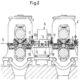
- Figure 2 shows the rolling phase of the strip 5.
- the induction heating device 6 is moved into the rolling line, so that the two-part inductor 12a, 12b is positioned above and below the strip 5 so that the strip 5 over the coils of the inductor 12a, 12b can be heated.
- the band 5 is positioned by the guide rollers 10 such that it runs in a plane centered on the inductor space 13 formed within the inductor 12a, 12b.
- An additional guide roller 14 between the two halves of the inductor 12a and 12b additionally supports the belt 5 and serves for the exact guidance of the belt 5 within the induction device 6.
- the pressure rollers 11 of the guide rollers 10 prevent the belt from fluttering and ensure that the belt runs smoothly.
- the tension measuring roller 8 is immersed in the belt 5, so that the measuring devices detect the tension of the belt 5 and can regulate the drives of the roll stands 1 and 2 so that a uniform belt tension is maintained, with which the belt 5 is exactly through the inductor 12a, 12b is performed.
- the inductor 12a, 12b is C-shaped in cross section, so that the induction coils, which are not described in more detail, can overlap the top and bottom of the band 5, and the inductor 12a, 12b are nevertheless removed from the region of the band can without having to unthread the tape 5.
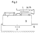
- the inductor 12a, 12b is arranged on the carriage denoted by 15 and shown roughly schematically, which can be moved on rails 16 in the direction of arrow 17.
- the roller table 7 is fastened on the same carriage 15, so that when the carriage 15 is moved (in the drawing plane) to the right, the inductor 12a, 12b move out of the area of the belt 5 and at the same time the roller table 7 can travel under the belt 5.
- the strip 5 can be threaded into the roll stand 2.
- the carriage 15 can be shifted to the left (in the plane of the drawing), so that the roller table reaches the position shown in FIG. 3 and the inductor 12a, 12b can grip around the strip.
- FIGS. 5 and 6 show the tension measuring roller 8 in a simplified enlarged representation, FIG. 5 representing the starting position when threading the strip and FIG. 6 the position in the rolling phase.
- the tension measuring roller is, for example, a so-called tensiometer roller, which uses a force measuring unit 15 to detect the pressure of the roller 8 on the belt 5 and in this way the belt tensile forces in the belt 5.
- the measurement signal is fed to a computer for evaluation, which gives a signal for controlling the rolling mill adjustment or the rolling mill drive from the measured values in order to regulate the uniform train in a known manner.
- the measuring roller 8 can be pivoted via the piston-cylinder unit 9, as shown in FIGS. 5 and 6. At 10, the guide roller arranged in front of the inductor can be seen, which defines the strip running plane of the strip 5 within the inductor. Obviously, this level is not influenced or changed by the tension measuring device.
- FIG. 7 shows an exemplary arrangement of the guide roller 10 which, as the arrow 17 shows, is adjustable in its height.
- the guide roller 10 can thus be set to different strip thicknesses s, so that the strip running plane can always be aligned with the center of the inductor 12a, 12b.
- the adjusting screw 20 is used to adjust the guide roller 10.
- FIGS. 8 and 9 show roughly simplified examples of how the inductor space 13 between the inductors 12a, 12b can be flooded with inert gas.
- the nozzles 21 are shielded by flaps 22 which reduce the outlet cross section between the inductor 12a, 12b and band 5.
- the lateral openings of the inductor 12a, 12b can also be closed by flaps 23 which pivot into position 25 via piston-cylinder units 24 when the inductor is to be moved out of the area of the band 5.
- the piston-cylinder unit time 9 of the tension measuring device is actuated so that the measuring roller 8 is immersed in the band 5 ( Figure 2), so that the tension of the strip 5 between the roll stands 1 and 2 can be controlled via the measured value.
- the inductor 12a, 12b is moved over the belt 5 by moving the carriage 15, the roller table 7 being simultaneously transported out of the area of the belt.
- the band 5 comes to rest on the guide rollers 10 and 14 and is held on the guide rollers 10 by means of the pressure rollers 11.
- the band 5 guided in the middle of the induction space 13 can now be heated by means of the inductor 12a, 12b, with a uniform heating of the band guided in a defined manner being expected.
- the inductor chamber 13 is flooded (FIGS. 8 and 9) with inert gas, for example nitrogen or argon, in order to displace the oxygen, which would otherwise lead to severe scaling of the strip surface.
- inert gas for example nitrogen or argon
Applications Claiming Priority (2)
| Application Number | Priority Date | Filing Date | Title |
|---|---|---|---|
| DE19502071 | 1995-01-16 | ||
| DE19502071 | 1995-01-16 |
Publications (2)
| Publication Number | Publication Date |
|---|---|
| EP0721813A1 true EP0721813A1 (fr) | 1996-07-17 |
| EP0721813B1 EP0721813B1 (fr) | 1999-01-27 |
Family
ID=7752185
Family Applications (1)
| Application Number | Title | Priority Date | Filing Date |
|---|---|---|---|
| EP95250305A Expired - Lifetime EP0721813B1 (fr) | 1995-01-16 | 1995-12-13 | Dispositif pour guider des bandes laminées à chaud à travers un inducteur |
Country Status (3)
| Country | Link |
|---|---|
| US (1) | US5910185A (fr) |
| EP (1) | EP0721813B1 (fr) |
| DE (1) | DE59504983D1 (fr) |
Cited By (4)
| Publication number | Priority date | Publication date | Assignee | Title |
|---|---|---|---|---|
| WO2012045585A3 (fr) * | 2010-10-08 | 2012-06-07 | Sms Siemag Ag | Train de laminage pour la fabrication d'une bande métallique et procédé de fabrication d'un train de laminage |
| WO2012080368A1 (fr) * | 2010-12-16 | 2012-06-21 | Sms Siemag Ag | Train de laminoir pour la production d'acier tubulaire et de bandes minces |
| EP3025799A1 (fr) | 2014-11-28 | 2016-06-01 | SMS group GmbH | Installation de laminage, installation de coulé-laminage et procédé de fabrication d'une bande de métal |
| EP2964404B1 (fr) | 2013-03-08 | 2017-05-10 | SMS group GmbH | Procédé de production d'une bande métallique au moyen de cylindres de coulée |
Families Citing this family (4)
| Publication number | Priority date | Publication date | Assignee | Title |
|---|---|---|---|---|
| KR20060118587A (ko) * | 2004-01-21 | 2006-11-23 | 제이에프이 스틸 가부시키가이샤 | 강판의 열처리장치와 그것을 구비한 강판의 제조라인 |
| DE102007022927A1 (de) * | 2006-05-26 | 2007-12-20 | Sms Demag Ag | Vorrichtung und Verfahren zum Herstellen eines Metallbandes durch Stranggießen |
| CN101939119B (zh) * | 2008-01-17 | 2013-05-29 | Ihi金属生产设备科技株式会社 | 输送装置和热轧装置以及输送方法和热轧方法 |
| CN107405658B (zh) * | 2015-03-09 | 2020-09-18 | 东芝三菱电机产业系统株式会社 | 轧制设备 |
Citations (12)
| Publication number | Priority date | Publication date | Assignee | Title |
|---|---|---|---|---|
| GB620432A (en) * | 1946-11-27 | 1949-03-24 | John Heywood Ludlow | Improvements relating to the heat treatment of strip metal by electromagnetic induction |
| EP0021995A1 (fr) * | 1979-06-26 | 1981-01-07 | Secim | Dispositif d'entrainement de bande |
| JPS5714413A (en) * | 1980-06-30 | 1982-01-25 | Nippon Steel Corp | Method and device for heating of edge part of hot rolled material |
| JPS5785601A (en) * | 1980-11-19 | 1982-05-28 | Nippon Steel Corp | Method and device for heating edge part of hot rolled material |
| EP0162361A2 (fr) | 1984-05-25 | 1985-11-27 | Sms Schloemann-Siemag Aktiengesellschaft | Dispositif de réglage de traction de la bande dans un train à feuillard à chaud |
| JPS61235020A (ja) * | 1985-04-10 | 1986-10-20 | Nippon Steel Corp | 圧延材端部誘導加熱におけるインダクタ位置設定方法 |
| JPS629704A (ja) * | 1985-07-05 | 1987-01-17 | Nippon Steel Corp | 熱間圧延方法 |
| DE3840812A1 (de) | 1988-05-26 | 1990-04-05 | Mannesmann Ag | Verfahren und anlage zur kontinuierlichen herstellung von stahlband oder stahlblech nach dem stranggussverfahren |
| JPH0342101A (ja) * | 1989-07-10 | 1991-02-22 | Hitachi Ltd | 圧延設備,圧延方法及び圧延制御方法 |
| JPH03238783A (ja) * | 1990-02-16 | 1991-10-24 | Nkk Corp | ビレットのオンライン加熱方法 |
| DE4028542A1 (de) * | 1990-09-06 | 1992-03-12 | Mannesmann Ag | Vorrichtung zum zwischenerwaermen von warmgewalztem band |
| EP0578524A1 (fr) * | 1992-06-24 | 1994-01-12 | Société CELES | Dispositif de sécurité de modules de chauffage ou de réchauffage inductif de produits métallurgiques |
Family Cites Families (13)
| Publication number | Priority date | Publication date | Assignee | Title |
|---|---|---|---|---|
| JPS5226224A (en) * | 1975-08-22 | 1977-02-26 | Canon Inc | Amending fluid |
| JPS5316939A (en) * | 1976-07-30 | 1978-02-16 | Nippon Steel Corp | Inducton heating method |
| JPS5388614A (en) * | 1977-01-14 | 1978-08-04 | Mitsubishi Electric Corp | Induction heating apparatus |
| EP0043956B1 (fr) * | 1980-07-16 | 1985-02-06 | Klöckner-Werke Aktiengesellschaft | Train de laminage pour produire un feuillard à chaud |
| SE8406062L (sv) * | 1984-11-30 | 1986-05-12 | Asea Ab | Induktiv kantvermare |
| JPH0677768B2 (ja) * | 1986-05-15 | 1994-10-05 | 石川島播磨重工業株式会社 | 幅圧下方法及びその制御装置 |
| JPH069705B2 (ja) * | 1986-11-18 | 1994-02-09 | 住友金属工業株式会社 | 厚鋼板製造ラインにおける誘導加熱装置 |
| US5195344A (en) * | 1987-03-06 | 1993-03-23 | Nippon Kokan Kabushiki Kaisha | Warm rolling facility for steel strip coils |
| JPH02303619A (ja) * | 1989-05-19 | 1990-12-17 | Kawasaki Steel Corp | 熱間シートバーの加熱方法 |
| US5550353A (en) * | 1990-01-31 | 1996-08-27 | Inductotherm Corp. | Induction heating coil assembly for prevent of circulating current in induction heating lines for continuous-cast products |
| JPH04172122A (ja) * | 1990-11-06 | 1992-06-19 | Sumitomo Metal Ind Ltd | 熱間圧延ラインにおける誘導加熱方法 |
| DE4220605A1 (de) * | 1992-06-24 | 1994-01-05 | Schloemann Siemag Ag | Anlage zur Herstellung von warmgewalztem Stahlband |
| US5540074A (en) * | 1994-12-07 | 1996-07-30 | Ipsco Enterprises Inc. | Unitary assembly of peripheral devices for use with steckel mill |
-
1995
- 1995-12-13 DE DE59504983T patent/DE59504983D1/de not_active Expired - Lifetime
- 1995-12-13 EP EP95250305A patent/EP0721813B1/fr not_active Expired - Lifetime
-
1996
- 1996-01-16 US US08/586,485 patent/US5910185A/en not_active Expired - Lifetime
Patent Citations (12)
| Publication number | Priority date | Publication date | Assignee | Title |
|---|---|---|---|---|
| GB620432A (en) * | 1946-11-27 | 1949-03-24 | John Heywood Ludlow | Improvements relating to the heat treatment of strip metal by electromagnetic induction |
| EP0021995A1 (fr) * | 1979-06-26 | 1981-01-07 | Secim | Dispositif d'entrainement de bande |
| JPS5714413A (en) * | 1980-06-30 | 1982-01-25 | Nippon Steel Corp | Method and device for heating of edge part of hot rolled material |
| JPS5785601A (en) * | 1980-11-19 | 1982-05-28 | Nippon Steel Corp | Method and device for heating edge part of hot rolled material |
| EP0162361A2 (fr) | 1984-05-25 | 1985-11-27 | Sms Schloemann-Siemag Aktiengesellschaft | Dispositif de réglage de traction de la bande dans un train à feuillard à chaud |
| JPS61235020A (ja) * | 1985-04-10 | 1986-10-20 | Nippon Steel Corp | 圧延材端部誘導加熱におけるインダクタ位置設定方法 |
| JPS629704A (ja) * | 1985-07-05 | 1987-01-17 | Nippon Steel Corp | 熱間圧延方法 |
| DE3840812A1 (de) | 1988-05-26 | 1990-04-05 | Mannesmann Ag | Verfahren und anlage zur kontinuierlichen herstellung von stahlband oder stahlblech nach dem stranggussverfahren |
| JPH0342101A (ja) * | 1989-07-10 | 1991-02-22 | Hitachi Ltd | 圧延設備,圧延方法及び圧延制御方法 |
| JPH03238783A (ja) * | 1990-02-16 | 1991-10-24 | Nkk Corp | ビレットのオンライン加熱方法 |
| DE4028542A1 (de) * | 1990-09-06 | 1992-03-12 | Mannesmann Ag | Vorrichtung zum zwischenerwaermen von warmgewalztem band |
| EP0578524A1 (fr) * | 1992-06-24 | 1994-01-12 | Société CELES | Dispositif de sécurité de modules de chauffage ou de réchauffage inductif de produits métallurgiques |
Non-Patent Citations (6)
| Title |
|---|
| PATENT ABSTRACTS OF JAPAN vol. 11, no. 180 (M - 597) 10 June 1987 (1987-06-10) * |
| PATENT ABSTRACTS OF JAPAN vol. 11, no. 78 (M - 570) 10 March 1987 (1987-03-10) * |
| PATENT ABSTRACTS OF JAPAN vol. 15, no. 178 (M - 1110) 8 May 1991 (1991-05-08) * |
| PATENT ABSTRACTS OF JAPAN vol. 16, no. 22 (E - 1156) 20 January 1992 (1992-01-20) * |
| PATENT ABSTRACTS OF JAPAN vol. 6, no. 178 (M - 155) 11 September 1982 (1982-09-11) * |
| PATENT ABSTRACTS OF JAPAN vol. 6, no. 74 (M - 127) 11 May 1982 (1982-05-11) * |
Cited By (8)
| Publication number | Priority date | Publication date | Assignee | Title |
|---|---|---|---|---|
| WO2012045585A3 (fr) * | 2010-10-08 | 2012-06-07 | Sms Siemag Ag | Train de laminage pour la fabrication d'une bande métallique et procédé de fabrication d'un train de laminage |
| RU2547062C2 (ru) * | 2010-10-08 | 2015-04-10 | Смс Зимаг Аг | Прокатный стан для изготовления металлической полосы и способ изготовления прокатного стана |
| WO2012080368A1 (fr) * | 2010-12-16 | 2012-06-21 | Sms Siemag Ag | Train de laminoir pour la production d'acier tubulaire et de bandes minces |
| RU2552802C2 (ru) * | 2010-12-16 | 2015-06-10 | Смс Зимаг Аг | Прокатный стан для изготовления трубной стали и тонкой полосы |
| EP2964404B1 (fr) | 2013-03-08 | 2017-05-10 | SMS group GmbH | Procédé de production d'une bande métallique au moyen de cylindres de coulée |
| EP3025799A1 (fr) | 2014-11-28 | 2016-06-01 | SMS group GmbH | Installation de laminage, installation de coulé-laminage et procédé de fabrication d'une bande de métal |
| WO2016083439A1 (fr) | 2014-11-28 | 2016-06-02 | Sms Group Gmbh | Laminoir, installation de laminage de coulée continue et procédé de production d'une bande métallique |
| EP3025799B1 (fr) | 2014-11-28 | 2017-05-24 | SMS group GmbH | Installation de laminage et inductance longitudinale pour l'usage dans une telle installation de laminage |
Also Published As
| Publication number | Publication date |
|---|---|
| EP0721813B1 (fr) | 1999-01-27 |
| US5910185A (en) | 1999-06-08 |
| DE59504983D1 (de) | 1999-03-11 |
Similar Documents
| Publication | Publication Date | Title |
|---|---|---|
| EP0415987B2 (fr) | Procede pour produire en continu du feuillard d'acier ou de la tole d'acier a partir de produits plats fabriques selon le procede de coulee continue en arc | |
| EP2155411B1 (fr) | Dispositif pour influer sur la répartition de température sur une largeur | |
| WO1997036699A1 (fr) | Procede et unite pour fabriquer un feuillard d'acier lamine a chaud | |
| EP0738547A1 (fr) | Laminoir steckel | |
| EP2964404A1 (fr) | Procédé de production d'une bande métallique au moyen de cylindres de coulée | |
| EP1446242B1 (fr) | Procede et dispositif de realisation en continu d'un feuillard metallique lamine a partir d'un metal en fusion | |
| EP2344287B1 (fr) | Procédé et dispositif pour le refroidissement d'une bande préliminaire ou d'une bande d'une ligne continue métallique dans un laminoir à chaud | |
| WO2003054236A1 (fr) | Procede et dispositif pour dresser et refroidir de maniere regulee un feuillard metallique large, notamment un feuillard d'acier ou une tole, sortant d'un laminoir a chaud pour feuillards | |
| EP0721813B1 (fr) | Dispositif pour guider des bandes laminées à chaud à travers un inducteur | |
| DE102007056192A1 (de) | Verfahren und Vorrichtung zum Herstellen eines Bandes aus Metall | |
| DE69827569T2 (de) | Bandsteuerung | |
| WO2016165933A1 (fr) | Installation de coulée et de laminage et procédé servant à faire fonctionner ladite installation | |
| DE10323796B3 (de) | Vorrichtung zum Erwärmen eines Metallbandes sowie mit einer derartigen Vorrichtung ausgestattete Anlagen zum Erzeugen von warmgewalztem Metallband | |
| AT409351B (de) | Verfahren und anlage zur herstellung eines metallbandes | |
| DE19844305A1 (de) | Kombiniertes Regelungssystem zur Erzeugung bestimmter Produkteigenschaften beim Walzen von Stahlqualitäten im austenitischen, gemischt austenitisch-ferritischen und ferritischen Bereich | |
| EP3027331B1 (fr) | Installation de laminage de coulée continue et procédé de fabrication de brames | |
| EP3284546A1 (fr) | Procédé de laminage d'un produit laminé dans un train de laminoir et train de laminoir | |
| EP0891826A1 (fr) | Procédé et dispositif pour la fabrication de bande à chaud et de bande à froid revêtue | |
| DE2613459A1 (de) | Verfahren und anlage zur vermeidung des schrottanfalles in kontinuierlichen breitbandstrassen | |
| DE4028542C2 (fr) | ||
| DE102010005226B4 (de) | Verfahren und Vorrichtung zum Bandgießen | |
| DE19830034A1 (de) | Verfahren und Vorrichtung zum Walzen von Warmbändern | |
| DE102016224822A1 (de) | Verfahren zum Walzen eines Walzguts in einer Walzstraße und Walzstraße | |
| EP4122616A1 (fr) | Procédé et dispositif de fabrication d'une bande métallique | |
| EP0707903A2 (fr) | Procédé et dispositif pour éviter un manque de parallélisme de profilés |
Legal Events
| Date | Code | Title | Description |
|---|---|---|---|
| PUAI | Public reference made under article 153(3) epc to a published international application that has entered the european phase |
Free format text: ORIGINAL CODE: 0009012 |
|
| AK | Designated contracting states |
Kind code of ref document: A1 Designated state(s): DE FR GB IT |
|
| 17P | Request for examination filed |
Effective date: 19960716 |
|
| 17Q | First examination report despatched |
Effective date: 19970520 |
|
| GRAG | Despatch of communication of intention to grant |
Free format text: ORIGINAL CODE: EPIDOS AGRA |
|
| GRAG | Despatch of communication of intention to grant |
Free format text: ORIGINAL CODE: EPIDOS AGRA |
|
| GRAH | Despatch of communication of intention to grant a patent |
Free format text: ORIGINAL CODE: EPIDOS IGRA |
|
| RBV | Designated contracting states (corrected) |
Designated state(s): DE FR GB IT |
|
| GRAH | Despatch of communication of intention to grant a patent |
Free format text: ORIGINAL CODE: EPIDOS IGRA |
|
| GRAA | (expected) grant |
Free format text: ORIGINAL CODE: 0009210 |
|
| AK | Designated contracting states |
Kind code of ref document: B1 Designated state(s): DE FR GB IT |
|
| ET | Fr: translation filed | ||
| REF | Corresponds to: |
Ref document number: 59504983 Country of ref document: DE Date of ref document: 19990311 |
|
| ITF | It: translation for a ep patent filed |
Owner name: GUZZI E RAVIZZA S.R.L. |
|
| GBT | Gb: translation of ep patent filed (gb section 77(6)(a)/1977) |
Effective date: 19990428 |
|
| PLBE | No opposition filed within time limit |
Free format text: ORIGINAL CODE: 0009261 |
|
| STAA | Information on the status of an ep patent application or granted ep patent |
Free format text: STATUS: NO OPPOSITION FILED WITHIN TIME LIMIT |
|
| 26N | No opposition filed | ||
| REG | Reference to a national code |
Ref country code: GB Ref legal event code: IF02 |
|
| PG25 | Lapsed in a contracting state [announced via postgrant information from national office to epo] |
Ref country code: IT Free format text: LAPSE BECAUSE OF NON-PAYMENT OF DUE FEES Effective date: 20101213 |
|
| PGFP | Annual fee paid to national office [announced via postgrant information from national office to epo] |
Ref country code: DE Payment date: 20131220 Year of fee payment: 19 |
|
| PGFP | Annual fee paid to national office [announced via postgrant information from national office to epo] |
Ref country code: GB Payment date: 20141219 Year of fee payment: 20 |
|
| PGFP | Annual fee paid to national office [announced via postgrant information from national office to epo] |
Ref country code: FR Payment date: 20141219 Year of fee payment: 20 |
|
| PGFP | Annual fee paid to national office [announced via postgrant information from national office to epo] |
Ref country code: IT Payment date: 20141222 Year of fee payment: 20 |
|
| REG | Reference to a national code |
Ref country code: DE Ref legal event code: R119 Ref document number: 59504983 Country of ref document: DE |
|
| PG25 | Lapsed in a contracting state [announced via postgrant information from national office to epo] |
Ref country code: DE Free format text: LAPSE BECAUSE OF NON-PAYMENT OF DUE FEES Effective date: 20150701 |
|
| REG | Reference to a national code |
Ref country code: GB Ref legal event code: PE20 Expiry date: 20151212 |
|
| PG25 | Lapsed in a contracting state [announced via postgrant information from national office to epo] |
Ref country code: GB Free format text: LAPSE BECAUSE OF EXPIRATION OF PROTECTION Effective date: 20151212 |