EP0721221A2 - Dispositifs FET et/ou bipolaire fabriqués dans du silicium mince vertical dans des structures silicium sur isolant - Google Patents
Dispositifs FET et/ou bipolaire fabriqués dans du silicium mince vertical dans des structures silicium sur isolant Download PDFInfo
- Publication number
- EP0721221A2 EP0721221A2 EP95119364A EP95119364A EP0721221A2 EP 0721221 A2 EP0721221 A2 EP 0721221A2 EP 95119364 A EP95119364 A EP 95119364A EP 95119364 A EP95119364 A EP 95119364A EP 0721221 A2 EP0721221 A2 EP 0721221A2
- Authority
- EP
- European Patent Office
- Prior art keywords
- silicon
- sidewalls
- impurity regions
- vertical
- devices
- Prior art date
- Legal status (The legal status is an assumption and is not a legal conclusion. Google has not performed a legal analysis and makes no representation as to the accuracy of the status listed.)
- Withdrawn
Links
- 229910052710 silicon Inorganic materials 0.000 title claims abstract description 137
- 239000010703 silicon Substances 0.000 title claims abstract description 137
- 239000012212 insulator Substances 0.000 title claims abstract description 9
- XUIMIQQOPSSXEZ-UHFFFAOYSA-N Silicon Chemical compound [Si] XUIMIQQOPSSXEZ-UHFFFAOYSA-N 0.000 claims abstract description 137
- 238000000034 method Methods 0.000 claims abstract description 35
- 238000009413 insulation Methods 0.000 claims abstract description 19
- 238000005516 engineering process Methods 0.000 claims abstract description 7
- 239000012535 impurity Substances 0.000 claims description 35
- 239000004065 semiconductor Substances 0.000 claims description 18
- 230000004888 barrier function Effects 0.000 claims description 16
- 230000000295 complement effect Effects 0.000 claims description 13
- 238000004519 manufacturing process Methods 0.000 claims description 10
- 238000005530 etching Methods 0.000 claims description 8
- 239000011248 coating agent Substances 0.000 claims description 6
- 238000000576 coating method Methods 0.000 claims description 6
- 230000005669 field effect Effects 0.000 claims 2
- 230000001590 oxidative effect Effects 0.000 claims 1
- 230000008569 process Effects 0.000 abstract description 21
- 239000010410 layer Substances 0.000 description 89
- 229910021420 polycrystalline silicon Inorganic materials 0.000 description 31
- 229920005591 polysilicon Polymers 0.000 description 31
- 239000000758 substrate Substances 0.000 description 23
- VYPSYNLAJGMNEJ-UHFFFAOYSA-N Silicium dioxide Chemical compound O=[Si]=O VYPSYNLAJGMNEJ-UHFFFAOYSA-N 0.000 description 21
- 229910052814 silicon oxide Inorganic materials 0.000 description 21
- 229910052581 Si3N4 Inorganic materials 0.000 description 19
- HQVNEWCFYHHQES-UHFFFAOYSA-N silicon nitride Chemical compound N12[Si]34N5[Si]62N3[Si]51N64 HQVNEWCFYHHQES-UHFFFAOYSA-N 0.000 description 19
- 229920002120 photoresistant polymer Polymers 0.000 description 8
- 238000005468 ion implantation Methods 0.000 description 6
- 239000000463 material Substances 0.000 description 6
- 238000005498 polishing Methods 0.000 description 6
- 150000004767 nitrides Chemical class 0.000 description 5
- 239000005388 borosilicate glass Substances 0.000 description 4
- 238000002955 isolation Methods 0.000 description 4
- 238000001465 metallisation Methods 0.000 description 4
- 238000001020 plasma etching Methods 0.000 description 4
- 230000008901 benefit Effects 0.000 description 3
- 230000015572 biosynthetic process Effects 0.000 description 3
- 230000007547 defect Effects 0.000 description 3
- -1 boron ions Chemical class 0.000 description 2
- 239000005380 borophosphosilicate glass Substances 0.000 description 2
- 238000000151 deposition Methods 0.000 description 2
- 230000008021 deposition Effects 0.000 description 2
- 239000011810 insulating material Substances 0.000 description 2
- 150000002500 ions Chemical class 0.000 description 2
- 230000003071 parasitic effect Effects 0.000 description 2
- 238000002161 passivation Methods 0.000 description 2
- 238000000206 photolithography Methods 0.000 description 2
- 239000011241 protective layer Substances 0.000 description 2
- 238000013459 approach Methods 0.000 description 1
- 229910052785 arsenic Inorganic materials 0.000 description 1
- 229910052796 boron Inorganic materials 0.000 description 1
- 229910021419 crystalline silicon Inorganic materials 0.000 description 1
- 239000007789 gas Substances 0.000 description 1
- 238000002513 implantation Methods 0.000 description 1
- 230000006872 improvement Effects 0.000 description 1
- 230000010354 integration Effects 0.000 description 1
- 238000012856 packing Methods 0.000 description 1
- 238000000059 patterning Methods 0.000 description 1
- 238000002360 preparation method Methods 0.000 description 1
- 230000001681 protective effect Effects 0.000 description 1
- 230000005855 radiation Effects 0.000 description 1
- 238000005382 thermal cycling Methods 0.000 description 1
Images


Classifications
-
- H—ELECTRICITY
- H01—ELECTRIC ELEMENTS
- H01L—SEMICONDUCTOR DEVICES NOT COVERED BY CLASS H10
- H01L29/00—Semiconductor devices adapted for rectifying, amplifying, oscillating or switching, or capacitors or resistors with at least one potential-jump barrier or surface barrier, e.g. PN junction depletion layer or carrier concentration layer; Details of semiconductor bodies or of electrodes thereof ; Multistep manufacturing processes therefor
- H01L29/66—Types of semiconductor device ; Multistep manufacturing processes therefor
- H01L29/68—Types of semiconductor device ; Multistep manufacturing processes therefor controllable by only the electric current supplied, or only the electric potential applied, to an electrode which does not carry the current to be rectified, amplified or switched
- H01L29/70—Bipolar devices
- H01L29/72—Transistor-type devices, i.e. able to continuously respond to applied control signals
- H01L29/73—Bipolar junction transistors
- H01L29/732—Vertical transistors
-
- H—ELECTRICITY
- H01—ELECTRIC ELEMENTS
- H01L—SEMICONDUCTOR DEVICES NOT COVERED BY CLASS H10
- H01L29/00—Semiconductor devices adapted for rectifying, amplifying, oscillating or switching, or capacitors or resistors with at least one potential-jump barrier or surface barrier, e.g. PN junction depletion layer or carrier concentration layer; Details of semiconductor bodies or of electrodes thereof ; Multistep manufacturing processes therefor
- H01L29/66—Types of semiconductor device ; Multistep manufacturing processes therefor
- H01L29/66007—Multistep manufacturing processes
- H01L29/66075—Multistep manufacturing processes of devices having semiconductor bodies comprising group 14 or group 13/15 materials
- H01L29/66227—Multistep manufacturing processes of devices having semiconductor bodies comprising group 14 or group 13/15 materials the devices being controllable only by the electric current supplied or the electric potential applied, to an electrode which does not carry the current to be rectified, amplified or switched, e.g. three-terminal devices
- H01L29/66234—Bipolar junction transistors [BJT]
- H01L29/66265—Thin film bipolar transistors
-
- H—ELECTRICITY
- H01—ELECTRIC ELEMENTS
- H01L—SEMICONDUCTOR DEVICES NOT COVERED BY CLASS H10
- H01L27/00—Devices consisting of a plurality of semiconductor or other solid-state components formed in or on a common substrate
- H01L27/02—Devices consisting of a plurality of semiconductor or other solid-state components formed in or on a common substrate including semiconductor components specially adapted for rectifying, oscillating, amplifying or switching and having at least one potential-jump barrier or surface barrier; including integrated passive circuit elements with at least one potential-jump barrier or surface barrier
- H01L27/12—Devices consisting of a plurality of semiconductor or other solid-state components formed in or on a common substrate including semiconductor components specially adapted for rectifying, oscillating, amplifying or switching and having at least one potential-jump barrier or surface barrier; including integrated passive circuit elements with at least one potential-jump barrier or surface barrier the substrate being other than a semiconductor body, e.g. an insulating body
- H01L27/1203—Devices consisting of a plurality of semiconductor or other solid-state components formed in or on a common substrate including semiconductor components specially adapted for rectifying, oscillating, amplifying or switching and having at least one potential-jump barrier or surface barrier; including integrated passive circuit elements with at least one potential-jump barrier or surface barrier the substrate being other than a semiconductor body, e.g. an insulating body the substrate comprising an insulating body on a semiconductor body, e.g. SOI
-
- H—ELECTRICITY
- H01—ELECTRIC ELEMENTS
- H01L—SEMICONDUCTOR DEVICES NOT COVERED BY CLASS H10
- H01L29/00—Semiconductor devices adapted for rectifying, amplifying, oscillating or switching, or capacitors or resistors with at least one potential-jump barrier or surface barrier, e.g. PN junction depletion layer or carrier concentration layer; Details of semiconductor bodies or of electrodes thereof ; Multistep manufacturing processes therefor
- H01L29/66—Types of semiconductor device ; Multistep manufacturing processes therefor
- H01L29/66007—Multistep manufacturing processes
- H01L29/66075—Multistep manufacturing processes of devices having semiconductor bodies comprising group 14 or group 13/15 materials
- H01L29/66227—Multistep manufacturing processes of devices having semiconductor bodies comprising group 14 or group 13/15 materials the devices being controllable only by the electric current supplied or the electric potential applied, to an electrode which does not carry the current to be rectified, amplified or switched, e.g. three-terminal devices
- H01L29/66409—Unipolar field-effect transistors
- H01L29/66477—Unipolar field-effect transistors with an insulated gate, i.e. MISFET
- H01L29/66666—Vertical transistors
-
- H—ELECTRICITY
- H01—ELECTRIC ELEMENTS
- H01L—SEMICONDUCTOR DEVICES NOT COVERED BY CLASS H10
- H01L29/00—Semiconductor devices adapted for rectifying, amplifying, oscillating or switching, or capacitors or resistors with at least one potential-jump barrier or surface barrier, e.g. PN junction depletion layer or carrier concentration layer; Details of semiconductor bodies or of electrodes thereof ; Multistep manufacturing processes therefor
- H01L29/66—Types of semiconductor device ; Multistep manufacturing processes therefor
- H01L29/68—Types of semiconductor device ; Multistep manufacturing processes therefor controllable by only the electric current supplied, or only the electric potential applied, to an electrode which does not carry the current to be rectified, amplified or switched
- H01L29/76—Unipolar devices, e.g. field effect transistors
- H01L29/772—Field effect transistors
- H01L29/78—Field effect transistors with field effect produced by an insulated gate
- H01L29/786—Thin film transistors, i.e. transistors with a channel being at least partly a thin film
- H01L29/78642—Vertical transistors
Definitions
- the transistors can be formed vertically thereby reducing the active lateral surface area required for the device. Therefore, vertical transistors, such as MOSFETs, have significantly higher packing density of, at least, a factor of 10 over their standard lateral counterparts.
- state of the art vertical MOSFETs have had a very limited application due to the silicon substrate used to fabricate them. When a silicon substrate is used, it acts as a common source or drain for all transistors and, because of this, only one type of vertical MOS transistor has been fabricated on a silicon wafer until recently.
- CMOS complementary MOS
- SOI silicon on insulator
- CMOS complementary MOS
- the starting point is a SOI wafer in which the source or drain are formed in the silicon above the insulating layer followed by an epitaxical deposition of a silicon layer. Such a process prevents interconnecting the buried source and drain between the islands.
- Bipolar integrated circuits provide higher speed operation and greater drive currents than the FET circuits. Further, the integration of FET and bipolar transistors on a single substrate has become highly desirable. However, SOI substrates predominately have been used in fabricating FETs, such as CMOS, because bipolar or biFET processes on SOI substrates have resulted in defect density problems caused by the buried insulating layer not being as defect free.
- SOI Silicon on Insulator
- Another object of the present invention is to provide a novel process having the ability of merging vertical complementary FETs and bipolars in SOI technology.
- a further object of the present invention is to provide a novel process implementing SOI technology without requiring expensive SOI substrates.
- An additional object of the present invention is to provide a novel vertical device structure in which the majority of the interconnections are in the same plane or level as the regions of the devices being interconnected thereby allowing greater flexibility in wiring the devices and minimizing the wiring length.
- the transistor structures are fabricated in thin vertical SOI walls whose silicon thickness is defined by a sidewall image and whose insulation portion is formed by insulation filled shallow trenches adjacent the outer silicon sidewall.
- SOI advantages of SOI are achieved with a conventional silicon substrate.
- the bottom of the silicon sidewalls are isolated from the silicon substrate by thermally grown oxide extending to the insulation filled trenches or by a P/N junction.
- functional circuits can be designed to be fabricated within a SOI cell with the regions, such as the source, drain and gate or the emitter, collector and base of the devices of the circuit being essentially interconnected within the silicon and in many cases in the same plane so that the wiring distance in the cell is minimized and the overall dimensions of functional circuit is minimized.
- FIG. 1 is a schematic view of an AND circuit which can be fabricated by the process of the present invention to form a novel vertical SOI device.
- FIG. 2a is a plan view of a cell of the present invention showing bottom oxide insulation and a continuous silicon sidewall.
- FIG. 2b is a plan view of a cell of the present invention showing a silicon bottom and a continuous silicon sidewall.
- FIGS. 3a and 3b are a plan view of a cell of the present invention showing the continuous silicon sidewall of FIGS. 2a and 2b divided into six device sections and with bottom oxide insulation.
- FIG. 4a is a plan view of the first level or plane of the SOI cell of FIG. 3a showing the drains of CMOS transistors of the circuit of FIG. 1 and their interconnections within the cell.
- FIG. 4b is a plan view of the first level or plane of the SOI cell of FIG. 3b showing the drains of CMOS transistors of the circuit of FIG. 1 and their interconnections within the cell and "c" connection outside the cell surrounded by vertical insulation.
- FIG. 5a is a plan view of the second level or plane of the SOI cell of FIG. 3 showing the gates of CMOS transistors of the circuit of FIG. 1 and their interconnections within the cell.
- FIG. 5b is a plan view of the second level or plane of the SOI cell of FIG. 3 showing the gates of CMOS transistors of the circuit of FIG. 1 and their interconnections within the cell and "a" and "b" connections outside the cell surrounded by vertical insulation.
- FIG. 6a is a plan view of the third level or plane of the SOI cell of FIG. 3 showing the sources of CMOS transistors of the circuit of FIG. 1 and their interconnections within the cell.
- FIG. 6b is a plan view of the third level or plane of the SOI cell of FIG. 3 showing the CMOS transistors of the circuit of FIG. 1 and their interconnections within the cell and "VDD" and “Gnd” out of the cell surrounded by vertical insulation.
- FIG. 7a is a plan view of the upper metallization level or plane of the SOI cell of FIG. 3 showing the contacts for interconnection to the devices of other SOI cells (not shown) and vertical insulation around the cell.
- FIG. 7b is a plan view of the upper level or plane of the SOI cell of FIG. 3 showing a top oxide insulation layer and vertical insulation around the cell.
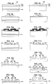
- FIGS. 8a, 9a, 10a, 11a, 12a, 13a, and 14a are cross sectional views showing a process for fabricating SOI cells of the present invention starting with a SOI substrate.
- FIGS. 8b, 9b, 10b, 11b, 12b, 12b', 13b and 14b are cross sectional views showing a process for fabricating SOI cells of the present invention starting with a silicon substrate.
- FIGS. 14, 15, 16, 17, 18, 19 and 20 are cross sectional views showing an alternative process of fabricating a plurality of SOI cells in accordance with the present invention.
- FIGS. 21, 22, 23, 24, 25, 26, 27 and 28 are cross sectional views of the continuation of the alternative process showing the beginning steps of fabricating either CMOS or complementary bipolar devices in the SOI cells of the present invention.
- FIGS. 29a, 30a, 31a, 32a, 33a and 34a are cross sectional views of the continuation of the alternative process showing the remaining steps of fabricating the CMOS devices in the SOI cells of the present invention.
- FIGS. 29b, 30b, 31b, 32b, 33b and 34b are cross sectional views of the continuation of the alternative process showing the remaining steps of fabricating the complementary bipolar devices in the SOI cells of the present invention.
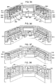
- FIGS. 35, 36, 37 and 38 are cross sectional, perspective views of a partial cell broken away during four of the steps of the alternative process showing the fabrication of both a CMOS device and a bipolar device in an SOI cell of the present invention.
- This circuit contains six transistors, three of which, P1, P2, and P3 are complementary to the other three transistors N1, N2, N3.
- This circuit 10 can be fabricated as three CMOS devices in an SOI cell of the present invention to yield a novel device structure as shown in FIGS. 2 through 7 with either the majority (FIGS. 2a through 7a) or all (FIGS. 2b through 7b) of the interconnections between the transistors being within the silicon body.
- an SOI cell 20a of the present invention is shown with a continuous silicon sidewall 21a and a bottom layer 22a of silicon oxide because the starting wafer is a conventional SOI wafer.
- the continuous silicon sidewall 21b is formed on a convention silicon wafer and the insulating bottom oxide layer 22b is thermally grown between and under the silicon sidewall as shown in FIG. 3b. Since only the bottom of the silicon sidewall 21b must be isolated from the silicon substrate 23b (FIG. 2b), a P/N junction (not shown) can be formed at the bottom of the sidewall to provide the electrical isolation from the silicon substrate.
- the single crystalline silicon sidewall of the SOI cell of the present invention is divided into device sections 24a, 24a', 25a, 25a' 26a and 26a' (FIG. 3a) and 24b, 24b', 25b, 25b', 26b, and 26b' (FIG. 3b) in which the transistor devices necessary to fabricate the circuit of FIG. 1 will be formed.
- FIG. 3a the device sections 24a, 24a', 25a, 25a' 26a and 26a'
- the drains (D) of the six transistors P1, P2, P3, N1, N2, and N3 are formed in sections 24a, 25a, 26a, 24a', 25a'and 26a'and the drains of P1, N1, and P2 are interconnected as shown by numeral 27a at the same level or in the same plane along with a contact pad 28a for a via connection.
- the drain of N2 is formed with a via connection 29a.
- the drains of P3 and N3 are interconnected as shown by numeral 31a along with a via connection 32a, which will provide the "c" output at the upper metallization level.
- the "c" output is formed with an external connection 32b at this level ,as shown in FIG. 4b, for linking to a device of another SOI cell (not shown) .
- the gates of P1 and N1 are interconnected as shown by the numeral 33a and formed with a connecting via 34a which will provide the input "a” at the upper metallization level.
- the gates of P2 and N2 are interconnected as shown by numeral 35a at this plane or level and formed with a connecting via 36a.
- a connecting via 37a is formed in this plane or level and vertically interconnects with via 32a FIG. 4a.
- the gates of P3 and N3 are interconnected as shown by numeral 38a (FIG. 5a) and 38b (FIG. 5b) and formed with a connecting pad 39a and 39b (FIGS. 5a and 5b) to connect with the via 28a and 28b (FIGS. 4a and 4b) of the drain level.
- inputs "a” and "b” are formed with external connections 40b and 41b, respectively, at this level for linking to device(s) of other SOI cell(s) (not shown).
- the "c" output connecting via pad of FIG. 5a is not required and the external connections are surrounded by vertical oxide insulation.
- the sources of P1 and P2 are interconnected as shown by numeral 43a with a connecting via 44a for VDD.
- the source of P3 is formed with a connecting via for VDD.
- the source of N1 is connected to a via 45a (FIGS. 6) to permit connection through the via 45a (FIG. 5) of the gate level to the drain of N2.
- the sources of N2 and N3 are each formed with a connecting vias 46a and 47a, respectively.
- connecting vias 48a, 49a and 50a are formed in this level for linking inputs “a” and “b” from the gate level and output “c” from the drain level, respectively.
- VDD and Gnd can be formed with external connections 51b and 52b at this level as shown in FIG. 6b. They are surrounded by vertical oxide insulation 53b and, with this alternative embodiment, the contact vias for "a", "b” and "c” of FIG 6a are not required.
- FIGS. 4a through 7a are within the silicon body and in the same levels or planes of the parts of the transistors, thereby minimizing the dimension of the cell for this AND circuit.
- the interconnections of the cell are totally within the silicon body are further reduced in wiring length by forming external connections to other SOI cells at the appropriate levels of the vertical transistors.
- connection to the various regions of the transistors can be made from the back of the vertical transistor to devices of other cells. If no external connections are required from the back of the silicon sidewalls of the SOI cell, the back of the cell is vertically surrounded by an insulating material 64a, 64b, such as oxide, as shown in FIGS. 7a and 7b.
- the starting silicon wafer can either be a conventional SOI wafer 100a with a buried oxide insulator layer 101a as shown in FIG. 8a or, preferably, is a conventional silicon wafer 100b without the buried oxide insulator layer as shown in FIG. 8b. If it is desired to use chem/mech polishing for planarization, a polish stop (not shown) of an oxide/nitride pad is patterned on the surface of the silicon wafer.
- an oxide layer 102a, 102b is formed on the silicon surface followed by a polysilicon layer 103a, 103b, which is patterned to define the inner dimensions of the cells as shown in FIGS. 9a and 9b.
- the pattered polysilicon 104a and 104b also functions as the mandrel for the silicon sidewalls to be formed and the thickness of the polysilicon layer determines the width of silicon sidewalls and the size of the vertical transistor to be formed therein. As shown in FIGS.
- the patterned polysilicon 104a and 104b is coated with a conformal layer 105a and 105b of silicon nitride and is anisotropically etched, such as by reactive ion etching, to form sidewall barriers 106a, 106a' 106b, and 106b'' , as shown in FIGS. 11a and 11b for etching, such as by reactive ion etching, the polysilicon mandrel 104a and 104b, the oxide layer 102a, 102b and the silicon body not under the silicon nitride barrier.
- the resulting vertical silicon structures 107a, 107a', 107b, and 107b' are shown in FIGS.
- the starting wafer is the conventional SOI wafer 100a of FIG. 8a
- an insulating layer 101a will be under the silicon sidewall cells as shown in FIG. 13a.
- the conventional silicon wafer of FIG 8b is used and an insulating layer 101b, as shown in FIG. 13b, of silicon oxide is formed after the silicon sidewall is protected by a thin silicon nitride layer 108b.
- the silicon in the bottom 109b of the open trench along with the + bottom portion of the silicon sidewalls is thermally oxided to silicon oxide so as to create a complete insulating bottom layer and form a SOI cell.
- insulation such as silicon oxide
- the complete bottom of the open trench does not have to be formed with insulation.
- the advantage of silicon sidewall cell process of FIGS. 8 through 13 is that the back walls of the silicon sidewalls are open and interconnection of device regions, such as sources, drains, and gates of FETs, and emitters, collectors, and bases of bipolar can be made between cells (pairs of silicon sidewalls) at the level of the particular device regions. This allows greater flexibility in wiring the devices of integrated circuit and minimizes the wiring length.
- CMOS devices in the SOI cells.
- a silicon substrate 200 which is formed with alternating layers, from top to bottom of herein silicon nitride 201, polysilicon 202, silicon nitride 203 and silicon oxide 204, and are used in forming the insulating trenches 205a, 205b, 205c, and 205d, herein filled with silicon oxide.
- the upper surface of the formed silicon oxide trenches are planarized, preferably by chem/mech polishing, with the silicon nitride layer 201 being the stopping surface.
- the combined thickness of top two layers, silicon nitride layer 201 and polysilicon layer 202 control the width of the to-be-formed silicon sidewalls and are selected accordingly, along with the depth of planarization, to achieve the desired width.
- These layers 201 and 202 are removed as shown in FIG. 15 to leave the upper ends of the trenches 206a, 206b, 206c, and 206d which are projecting above the other two layers 203 and 204, and which will serve as mandrels for forming the silicon sidewalls to be formed.
- a conformal coating of polysilicon 207 is deposited as shown in FIG.
- the polysilicon barriers is first oxidized as shown in FIG. 17 to provide a material with etch selectivity different from the silicon. After etching the silicon body, the resulting structure is shown in FIG.
- each of open trenches 209, 210, and 211 each respectively separating silicon sidewalls 212a'and 212b, 212b' and 212c, and 212c' and 212d which are backed by insulating trenches 205a, 205b, 205c, and 205d, respectively, herein silicon oxide.
- the etching is anisotropic, such as reactive ion etching, with the appropriate gases for the material being etched as is well known in the art.
- Each of open trenches with the silicon sidewalls backed by insulating trenches is a partial vertical SOI cell and, if the starting substrate were a SOI substrate, the bottom of the cell also will be insulated which, is not shown in this embodiment.
- the bottom insulating layer is formed in the next step, as shown in FIG. 18.
- a silicon nitride barrier layer 213 is formed on each of the silicon sidewalls, herein including the nitride and oxide layers 203 and 204.
- a layer of silicon oxide 214 is thermally grown using the silicon in each of the open trenches, such as 209, 210, and 211, to a thickness sufficient to permit lateral growth to abut the silicon oxide trenches 205a, 205b, 205c, and 205d backing the silicon sidewalls.
- each of the cells is surrounded by insulating material, both vertically and at the bottom of the cell in this embodiment which started with a conventional silicon wafer.
- Semiconductor devices now can be fabricated in the silicon sidewalls.
- CMOS and complementary bipolars devices in the silicon sidewalls 212a', 212b, 212b', and 212c.
- the open cells are filled with polysilicon 215 which is planarized herein by chem/mech polishing to the surface of the silicon nitride 203 and partially removed by anisotropic etching, herein reactive ion etching, to leave a polysilcon layer 215a at the bottom of cells bridging between the silicon sidewalls as shown in FIG. 21.
- the chem/mech polishing removed the oxide converted polysilicon barriers 208a through 208d'(FIG.
- a photoresist layer 216 is applied and patterned so that only one half of the open trenches 209, 210, and 211, including half of the polysilicon layer 215a is exposed.
- the exposed polysilicon is converted to P+ by an impurity, herein boron ions, preferably by ion implantating at 90 degrees.
- the other portion of polysilicon 215a is converted to N+ by similar steps of applying and patterning another photoresist layer 217 to expose the other portion of the polysilicon layer 215a to an N+ impurity, herein arsenic ions, preferably by ion implantating at 90 degrees.
- the doped polysilicon layer 215a Before forming the channels of the vertical CMOS devices, the doped polysilicon layer 215a must be isolated. As is shown in FIG. 24, silicon nitride barrier layers 218 are formed on the silicon sidewalls, such as 212a', 212b, 212b', 212c, 212c', and 212d and the nitride and oxide layers 203 and 204. Next, silicon oxide layers 219 are grown in the polysilicon layer 215a as shown in FIG. 25.
- either BoroSilicate Glass (BSG) or BoroPhosphoSilicate Glass (BPSG) can be deposited in place of the grown oxide to perform the isolation function of the silicon oxide layers 219 and this alternative step eliminates the need for the silicon nitride barrier layers 218 (FIG. 24).
- BSG BoroSilicate Glass
- BPSG BoroPhosphoSilicate Glass
- a channel oxide layer 220 is grown as shown in FIG. 26 and, if oxide isolation is used in the previous step, the silicon nitride barrier layers 218 must be removed first.
- the N doped channel is formed in one silicon sidewall as shown in FIG. 27 and the P doped channel is formed in the other silicon sidewall by another patterned photoresist layer 222 as shown in FIG.
- a polysilcon layer 223a is deposited on the oxide layer 219 and it bridges between the oxide channel layers 220 as shown in FIG. 29a.
- the height of the polysilicon layer 223a determines the initial channel length.
- bipolar devices are at the point of a polysilicon layer 223b having been formed and it bridges between the bases in the silicon sidewalls, such as 212a' and 212b, 212b'and 212c, and 212c' and 212d.
- FIGS. 30a through 34a will be used to describe the completion of CMOS devices from FIG 29a using the method of the present invention. Then, FIGS. 30b through 34b will be used to describe the completion of complementary bipolar devices from FIG 29b using the method of the present invention.
- an oxide layer 224a is thermally grown in the polysilicon layer 223a and the upper portion 225a of the exposed silicon sidewalls, after removing the oxide and nitride layers 203 and 204 at the top of the silicon sidewalls.
- a photoresist layer 226a is applied and patterned permit doping the exposed portion of the polysilcon layer 223a and the exposed upper portion 225a of the silicon sidewalls with a P+ impurity as shown in FIG. 31 and a N+ impurity as shown in FIG. 32 using another photoresist layer 227a.
- the silicon wafer is thermally cycled to drive them in, as shown in FIG. 33 and create the profiles of the impurities.
- the drive-in depth of the source impurity determines the final channel length.
- the surface of the wafer is passivated with a conventional passivation material, such as BSG 228a, and patterned to form openings for contacts 229a, 230a, and 231a to the two sources, S1 and S2, and the common gate, G, respectively, as shown in FIG. 34a.
- An oxide layer 224b is thermally grown in the polysilicon layer 223b and the upper portion 225b of the exposed silicon sidewalls 212a through 212d'.
- a photoresist layer 226b is applied and patterned to permit doping of the upper portion 225a of the silicon sidewalls for the emitter regions, preferably by ion implantation at 90 degrees, with a P+ impurity as shown in FIG. 31b and a N+ impurity as shown in FIG. 32b using another photoresist layer 227b.
- the silicon wafer is thermally cycled to drive them in as shown in FIG. 33b.
- the surface of the wafer is passivated with conventional passivation material, such as BSG 228b, and patterned to from openings for contacts 229b, 230b, and 231b to the two emitters, E1 and E2, and the common base, B, respectively, as shown in FIG. 34b.
- FIGS. 35 through 38 show in perspective the fabrication of a CMOS device in two of the sections and a bipolar device in a third section. Since the steps of forming both CMOS and complementary bipolar devices have been previously shown in FIGS 14 through 34 and described relative to those FIGS., only four steps in the process of the present invention are used for this illustration.
- FIG. 35 shows a broken away perspective cross- sectional view of three silicon sidewall sections 300, 301, and 302, each of the three sections being backed by an isolating trench 304, herein of silicon oxide.
- Two isolating trenches 305 separate the three silicon sidewall sections and herein are silicon oxide.
- the starting substrate is a conventional silicon substrate and an isolating layer 306, herein thermally grown silicon oxide, is formed at the bottom of the silicon sidewalls in a previous step not shown but corresponds to FIG. 18 and the description thereof.
- a polysilicon layer 307 is deposited on the isolating layer 306 and doped with P+ and N+ impurities as shown in FIGS. 35 through 38.
- the doping is achieved by ion implantation, and the steps for forming the doped polysilicon layers correspond to the steps of FIGS. 21 through 23 and the description thereof.
- Atop the silicon sidewall sections are layers of silicon oxide 310 and silicon nitride 311 in that order which were needed in the previous processing steps and also be needed in the subsequent processing steps.
- Formed adjacent of the faces of the silicon sidewall sections 300 and 302 of the CMOS devices is a vertical silicon nitride layer 312. This layer also is formed adjacent the bilpolar section 301 but, due the cross section, it does not show.
- the silicon nitride layer 312 is to provide a protective barrier for the faces of the silicon sidewalls when an oxide layer 313 (FIGS. 36 through 38) is thermally grown in the polysilicon layer 307.
- FIG. 35 corresponds to FIG. 24.
- the silicon nitride layer 312 is removed from faces of silicon sidewalls 300 and 302, but not 301 to permit the formation of a gate oxide layer 314 (FIG. 36) on the CMOS device but not the bipolar device.
- the silicon nitride layer (not shown) on the bipolar device is removed and, preferably, an silicon oxide protective layer is formed prior to the ion implantation of the base impurity.
- the silicon oxide protective layer is removed. Further explanation on this aspect of the fabrication of the bipolar can be found in the description associated with FIG. 29b.
- the three silicon sidewalls have progressed to where the gate oxide layer 314 is formed and the center region of the silicon sidewalls are doped with the appropriate impurity for the gates 315 of the CMOS device and for the base 316 of the bipolar device.
- a second polysilicon layer 317 is deposited on the oxide isolating layer 313 and is formed with an isolating layer 318 on its upper surface.
- the fabrication of the CMOS device and bipolar device are at the stage where the silicon oxide and silicon nitride layers 308 and 309 are removed along with upper portion of the silicon oxide trenches 304 by preferably chem/mech polishing.
- the upper regions of the silicon sidewalls 300 and 302 are doped with the appropriate impurities as shown to form the sources 319 of the CMOS device and silicon sidewall 301 is doped to form the emitter 320 of the bipolar device, herein by ion implantation at 90 degrees.
- the polysilicon layer 317 is implanted at the same time with the appropriate impurity as shown.
- FIG. 37 corresponds to FIGS. 33a and 33b and involved the steps shown in FIGS. 30a through 32a and FIGS. 30b through 32b and the description thereof.
- FIG. 38 shows CMOS device and the bipolar device with a passivating layer 321 and contacts made to the sources, S1 and S2, and the gate, G, of the CMOS device and the emitter, E, of the bipolar device.
- the contacts of the drains of the CMOS device and the collector and base of the bipolar device are not shown. It will be recognized by one skilled in the art that the contacts do not have to made from the surface as shown but can be made between devices within the cell as illustrated in FIGS. 2a and 2b through FIGS. 7a and 7b.
Applications Claiming Priority (2)
| Application Number | Priority Date | Filing Date | Title |
|---|---|---|---|
| US368069 | 1995-01-03 | ||
| US08/368,069 US5581101A (en) | 1995-01-03 | 1995-01-03 | FET and/or bipolar devices formed in thin vertical silicon on insulator (SOI) structures |
Publications (1)
| Publication Number | Publication Date |
|---|---|
| EP0721221A2 true EP0721221A2 (fr) | 1996-07-10 |
Family
ID=23449754
Family Applications (1)
| Application Number | Title | Priority Date | Filing Date |
|---|---|---|---|
| EP95119364A Withdrawn EP0721221A2 (fr) | 1995-01-03 | 1995-12-08 | Dispositifs FET et/ou bipolaire fabriqués dans du silicium mince vertical dans des structures silicium sur isolant |
Country Status (4)
| Country | Link |
|---|---|
| US (2) | US5581101A (fr) |
| EP (1) | EP0721221A2 (fr) |
| KR (1) | KR100199075B1 (fr) |
| TW (1) | TW359035B (fr) |
Cited By (12)
| Publication number | Priority date | Publication date | Assignee | Title |
|---|---|---|---|---|
| WO1998042026A1 (fr) * | 1997-03-19 | 1998-09-24 | Siemens Aktiengesellschaft | Transistor mos vertical et son procede de production |
| WO1999004436A1 (fr) * | 1997-07-18 | 1999-01-28 | Infineon Technologies Ag | Procede pour la fabrication d'un transistor mos vertical |
| EP0899783A2 (fr) * | 1997-08-22 | 1999-03-03 | Siemens Aktiengesellschaft | Arrangement de circuit comportant au moins quatre transistors et procédé de fabrication |
| WO2000067313A1 (fr) * | 1999-04-30 | 2000-11-09 | Infineon Technologies North America Corp. | Transistor a grille double |
| WO2005079182A2 (fr) | 2004-01-22 | 2005-09-01 | International Business Machines Corporation | Dispositifs mos de type fin-fet vertical |
| US7015106B2 (en) | 2003-09-16 | 2006-03-21 | Samsung Electronics Co., Ltd. | Double gate field effect transistor and method of manufacturing the same |
| US7087506B2 (en) | 2003-06-26 | 2006-08-08 | International Business Machines Corporation | Method of forming freestanding semiconductor layer |
| EP2284878A3 (fr) * | 2009-08-11 | 2013-07-31 | Unisantis Electronics Singapore Pte. Ltd. | Dispositif semi-conducteur et procédé de production |
| US8642426B2 (en) | 2009-03-25 | 2014-02-04 | Unisantis Electronics Singapore Pte Ltd. | Semiconductor device and production method therefor |
| US8772881B2 (en) | 2009-06-05 | 2014-07-08 | Unisantis Electronics Singapore Pte Ltd. | Semiconductor device |
| WO2016133569A1 (fr) * | 2015-02-17 | 2016-08-25 | Sandisk Technologies Llc | Transistor vertical et structure d'interconnexion locale |
| US10032908B1 (en) | 2017-01-06 | 2018-07-24 | Sandisk Technologies Llc | Multi-gate vertical field effect transistor with channel strips laterally confined by gate dielectric layers, and method of making thereof |
Families Citing this family (57)
| Publication number | Priority date | Publication date | Assignee | Title |
|---|---|---|---|---|
| EP0683921B1 (fr) * | 1993-02-04 | 2004-06-16 | Cornell Research Foundation, Inc. | Microstructures et procede a masque unique utilisant des monocristaux pour leur fabrication |
| US5795810A (en) * | 1995-03-29 | 1998-08-18 | Texas Instruments Incorporated | Deep mesa isolation in SOI |
| US20010048147A1 (en) * | 1995-09-14 | 2001-12-06 | Hideki Mizuhara | Semiconductor devices passivation film |
| US6326318B1 (en) | 1995-09-14 | 2001-12-04 | Sanyo Electric Co., Ltd. | Process for producing semiconductor devices including an insulating layer with an impurity |
| US6825132B1 (en) | 1996-02-29 | 2004-11-30 | Sanyo Electric Co., Ltd. | Manufacturing method of semiconductor device including an insulation film on a conductive layer |
| KR100383498B1 (ko) | 1996-08-30 | 2003-08-19 | 산요 덴키 가부시키가이샤 | 반도체 장치 제조방법 |
| US6288438B1 (en) * | 1996-09-06 | 2001-09-11 | Sanyo Electric Co., Ltd. | Semiconductor device including insulation film and fabrication method thereof |
| US6283677B1 (en) * | 1997-03-03 | 2001-09-04 | The United States Of America As Represented By The Secretary Of The Navy | Tailorable elastomeric composite pneumatic fender system for absorbing high energy impact |
| US5864158A (en) * | 1997-04-04 | 1999-01-26 | Advanced Micro Devices, Inc. | Trench-gated vertical CMOS device |
| US6031269A (en) * | 1997-04-18 | 2000-02-29 | Advanced Micro Devices, Inc. | Quadruple gate field effect transistor structure for use in integrated circuit devices |
| US5936280A (en) | 1997-04-21 | 1999-08-10 | Advanced Micro Devices, Inc. | Multilayer quadruple gate field effect transistor structure for use in integrated circuit devices |
| US5889302A (en) * | 1997-04-21 | 1999-03-30 | Advanced Micro Devices, Inc. | Multilayer floating gate field effect transistor structure for use in integrated circuit devices |
| US5894152A (en) * | 1997-06-18 | 1999-04-13 | International Business Machines Corporation | SOI/bulk hybrid substrate and method of forming the same |
| US6150687A (en) * | 1997-07-08 | 2000-11-21 | Micron Technology, Inc. | Memory cell having a vertical transistor with buried source/drain and dual gates |
| US5886382A (en) * | 1997-07-18 | 1999-03-23 | Motorola, Inc. | Trench transistor structure comprising at least two vertical transistors |
| US6690084B1 (en) | 1997-09-26 | 2004-02-10 | Sanyo Electric Co., Ltd. | Semiconductor device including insulation film and fabrication method thereof |
| US6528837B2 (en) | 1997-10-06 | 2003-03-04 | Micron Technology, Inc. | Circuit and method for an open bit line memory cell with a vertical transistor and trench plate trench capacitor |
| US5914511A (en) * | 1997-10-06 | 1999-06-22 | Micron Technology, Inc. | Circuit and method for a folded bit line memory using trench plate capacitor cells with body bias contacts |
| US5907170A (en) * | 1997-10-06 | 1999-05-25 | Micron Technology, Inc. | Circuit and method for an open bit line memory cell with a vertical transistor and trench plate trench capacitor |
| US6069390A (en) | 1998-01-15 | 2000-05-30 | International Business Machines Corporation | Semiconductor integrated circuits with mesas |
| US6177299B1 (en) | 1998-01-15 | 2001-01-23 | International Business Machines Corporation | Transistor having substantially isolated body and method of making the same |
| US6492684B2 (en) | 1998-01-20 | 2002-12-10 | International Business Machines Corporation | Silicon-on-insulator chip having an isolation barrier for reliability |
| US6133610A (en) * | 1998-01-20 | 2000-10-17 | International Business Machines Corporation | Silicon-on-insulator chip having an isolation barrier for reliability and process of manufacture |
| US6242775B1 (en) | 1998-02-24 | 2001-06-05 | Micron Technology, Inc. | Circuits and methods using vertical complementary transistors |
| US5963469A (en) | 1998-02-24 | 1999-10-05 | Micron Technology, Inc. | Vertical bipolar read access for low voltage memory cell |
| US6246083B1 (en) | 1998-02-24 | 2001-06-12 | Micron Technology, Inc. | Vertical gain cell and array for a dynamic random access memory |
| US6124729A (en) | 1998-02-27 | 2000-09-26 | Micron Technology, Inc. | Field programmable logic arrays with vertical transistors |
| US5880006A (en) * | 1998-05-22 | 1999-03-09 | Vlsi Technology, Inc. | Method for fabrication of a semiconductor device |
| US6794283B2 (en) | 1998-05-29 | 2004-09-21 | Sanyo Electric Co., Ltd. | Semiconductor device and fabrication method thereof |
| US6208164B1 (en) | 1998-08-04 | 2001-03-27 | Micron Technology, Inc. | Programmable logic array with vertical transistors |
| US5977579A (en) * | 1998-12-03 | 1999-11-02 | Micron Technology, Inc. | Trench dram cell with vertical device and buried word lines |
| JP3314760B2 (ja) * | 1999-05-24 | 2002-08-12 | 日本電気株式会社 | 静電保護素子、静電保護回路及び半導体装置 |
| JP3390704B2 (ja) * | 1999-08-26 | 2003-03-31 | 株式会社半導体理工学研究センター | 強誘電体不揮発性メモリ |
| US6265250B1 (en) * | 1999-09-23 | 2001-07-24 | Advanced Micro Devices, Inc. | Method for forming SOI film by laser annealing |
| US6320228B1 (en) | 2000-01-14 | 2001-11-20 | Advanced Micro Devices, Inc. | Multiple active layer integrated circuit and a method of making such a circuit |
| US6743680B1 (en) | 2000-06-22 | 2004-06-01 | Advanced Micro Devices, Inc. | Process for manufacturing transistors having silicon/germanium channel regions |
| US6429484B1 (en) | 2000-08-07 | 2002-08-06 | Advanced Micro Devices, Inc. | Multiple active layer structure and a method of making such a structure |
| KR100374554B1 (ko) * | 2000-09-22 | 2003-03-04 | 주식회사 하이닉스반도체 | 에스오아이 소자의 반도체 몸체-기판 접촉 구조 및 그제조방법 |
| US7163864B1 (en) * | 2000-10-18 | 2007-01-16 | International Business Machines Corporation | Method of fabricating semiconductor side wall fin |
| US6886110B2 (en) * | 2000-11-21 | 2005-04-26 | Wind River Systems, Inc. | Multiple device scan chain emulation/debugging |
| US6790722B1 (en) | 2000-11-22 | 2004-09-14 | International Business Machines Corporation | Logic SOI structure, process and application for vertical bipolar transistor |
| US6709935B1 (en) | 2001-03-26 | 2004-03-23 | Advanced Micro Devices, Inc. | Method of locally forming a silicon/geranium channel layer |
| US6461900B1 (en) * | 2001-10-18 | 2002-10-08 | Chartered Semiconductor Manufacturing Ltd. | Method to form a self-aligned CMOS inverter using vertical device integration |
| US6917110B2 (en) * | 2001-12-07 | 2005-07-12 | Sanyo Electric Co., Ltd. | Semiconductor device comprising an interconnect structure with a modified low dielectric insulation layer |
| US7372091B2 (en) * | 2004-01-27 | 2008-05-13 | Micron Technology, Inc. | Selective epitaxy vertical integrated circuit components |
| US7312125B1 (en) | 2004-02-05 | 2007-12-25 | Advanced Micro Devices, Inc. | Fully depleted strained semiconductor on insulator transistor and method of making the same |
| KR100582374B1 (ko) * | 2004-09-08 | 2006-05-22 | 매그나칩 반도체 유한회사 | 고전압 트랜지스터 및 그 제조 방법 |
| KR100729923B1 (ko) * | 2005-03-31 | 2007-06-18 | 주식회사 하이닉스반도체 | 스텝 sti 프로파일을 이용한 낸드 플래쉬 메모리 소자의트랜지스터 형성방법 |
| US7504685B2 (en) | 2005-06-28 | 2009-03-17 | Micron Technology, Inc. | Oxide epitaxial isolation |
| US7439135B2 (en) * | 2006-04-04 | 2008-10-21 | International Business Machines Corporation | Self-aligned body contact for a semiconductor-on-insulator trench device and method of fabricating same |
| US7923373B2 (en) | 2007-06-04 | 2011-04-12 | Micron Technology, Inc. | Pitch multiplication using self-assembling materials |
| KR101517390B1 (ko) * | 2008-11-03 | 2015-05-04 | 삼성전자주식회사 | 수직형 반도체 소자 및 이의 제조 방법. |
| US8633055B2 (en) | 2011-12-13 | 2014-01-21 | International Business Machines Corporation | Graphene field effect transistor |
| US9627531B1 (en) * | 2015-10-30 | 2017-04-18 | Taiwan Semiconductor Manufacturing Company, Ltd. | Field-effect transistor with dual vertical gates |
| US9859172B1 (en) | 2016-09-29 | 2018-01-02 | International Business Machines Corporation | Bipolar transistor compatible with vertical FET fabrication |
| US10332972B2 (en) * | 2017-11-20 | 2019-06-25 | International Business Machines Corporation | Single column compound semiconductor bipolar junction transistor fabricated on III-V compound semiconductor surface |
| US11615992B2 (en) | 2020-01-15 | 2023-03-28 | International Business Machines Corporation | Substrate isolated VTFET devices |
Family Cites Families (5)
| Publication number | Priority date | Publication date | Assignee | Title |
|---|---|---|---|---|
| US4753896A (en) * | 1986-11-21 | 1988-06-28 | Texas Instruments Incorporated | Sidewall channel stop process |
| US4982266A (en) * | 1987-12-23 | 1991-01-01 | Texas Instruments Incorporated | Integrated circuit with metal interconnecting layers above and below active circuitry |
| JPH02246259A (ja) * | 1989-03-20 | 1990-10-02 | Fujitsu Ltd | 半導体装置およびその製造方法 |
| KR920010963A (ko) * | 1990-11-23 | 1992-06-27 | 오가 노리오 | Soi형 종채널 fet 및 그 제조방법 |
| JP3202223B2 (ja) * | 1990-11-27 | 2001-08-27 | 日本電気株式会社 | トランジスタの製造方法 |
-
1995
- 1995-01-03 US US08/368,069 patent/US5581101A/en not_active Expired - Fee Related
- 1995-07-31 TW TW084107936A patent/TW359035B/zh active
- 1995-12-08 EP EP95119364A patent/EP0721221A2/fr not_active Withdrawn
- 1995-12-12 KR KR1019950048705A patent/KR100199075B1/ko not_active IP Right Cessation
-
1996
- 1996-09-12 US US08/713,061 patent/US5723370A/en not_active Expired - Lifetime
Non-Patent Citations (1)
| Title |
|---|
| None |
Cited By (23)
| Publication number | Priority date | Publication date | Assignee | Title |
|---|---|---|---|---|
| WO1998042026A1 (fr) * | 1997-03-19 | 1998-09-24 | Siemens Aktiengesellschaft | Transistor mos vertical et son procede de production |
| WO1999004436A1 (fr) * | 1997-07-18 | 1999-01-28 | Infineon Technologies Ag | Procede pour la fabrication d'un transistor mos vertical |
| US6337247B1 (en) | 1997-07-18 | 2002-01-08 | Infineon Technologies Ag | Method of producing a vertical MOS transistor |
| EP0899783A2 (fr) * | 1997-08-22 | 1999-03-03 | Siemens Aktiengesellschaft | Arrangement de circuit comportant au moins quatre transistors et procédé de fabrication |
| EP0899783A3 (fr) * | 1997-08-22 | 2000-08-16 | Siemens Aktiengesellschaft | Arrangement de circuit comportant au moins quatre transistors et procédé de fabrication |
| KR100547400B1 (ko) * | 1997-08-22 | 2006-03-23 | 지멘스 악티엔게젤샤프트 | 4개이상의트랜지스터를가진회로장치및그제조방법 |
| WO2000067313A1 (fr) * | 1999-04-30 | 2000-11-09 | Infineon Technologies North America Corp. | Transistor a grille double |
| US7709892B2 (en) | 2003-06-26 | 2010-05-04 | International Business Machines Corporation | Semiconductor device having freestanding semiconductor layer |
| US7087506B2 (en) | 2003-06-26 | 2006-08-08 | International Business Machines Corporation | Method of forming freestanding semiconductor layer |
| US7288823B2 (en) | 2003-09-16 | 2007-10-30 | Samsung Electronics Co., Ltd. | Double gate field effect transistor and method of manufacturing the same |
| US7015106B2 (en) | 2003-09-16 | 2006-03-21 | Samsung Electronics Co., Ltd. | Double gate field effect transistor and method of manufacturing the same |
| EP1711966A2 (fr) * | 2004-01-22 | 2006-10-18 | International Business Machines Corporation | Dispositifs mos de type fin-fet vertical |
| WO2005079182A2 (fr) | 2004-01-22 | 2005-09-01 | International Business Machines Corporation | Dispositifs mos de type fin-fet vertical |
| EP1711966A4 (fr) * | 2004-01-22 | 2011-02-16 | Ibm | Dispositifs mos de type fin-fet vertical |
| US8642426B2 (en) | 2009-03-25 | 2014-02-04 | Unisantis Electronics Singapore Pte Ltd. | Semiconductor device and production method therefor |
| US8772881B2 (en) | 2009-06-05 | 2014-07-08 | Unisantis Electronics Singapore Pte Ltd. | Semiconductor device |
| EP2284878A3 (fr) * | 2009-08-11 | 2013-07-31 | Unisantis Electronics Singapore Pte. Ltd. | Dispositif semi-conducteur et procédé de production |
| US8558317B2 (en) | 2009-08-11 | 2013-10-15 | Unisantis Electronics Singapore Pte Ltd. | Semiconductor device and production method |
| US9059309B2 (en) | 2009-08-11 | 2015-06-16 | Unisantis Electronics Singapore Pte Ltd. | Semiconductor device and production method |
| US9484268B2 (en) | 2009-08-11 | 2016-11-01 | Unisantis Electronics Singapore Pte Ltd. | Semiconductor device and production method |
| WO2016133569A1 (fr) * | 2015-02-17 | 2016-08-25 | Sandisk Technologies Llc | Transistor vertical et structure d'interconnexion locale |
| US9583615B2 (en) | 2015-02-17 | 2017-02-28 | Sandisk Technologies Llc | Vertical transistor and local interconnect structure |
| US10032908B1 (en) | 2017-01-06 | 2018-07-24 | Sandisk Technologies Llc | Multi-gate vertical field effect transistor with channel strips laterally confined by gate dielectric layers, and method of making thereof |
Also Published As
| Publication number | Publication date |
|---|---|
| US5581101A (en) | 1996-12-03 |
| TW359035B (en) | 1999-05-21 |
| US5723370A (en) | 1998-03-03 |
| KR100199075B1 (ko) | 1999-07-01 |
| KR960030430A (ko) | 1996-08-17 |
Similar Documents
| Publication | Publication Date | Title |
|---|---|---|
| US5581101A (en) | FET and/or bipolar devices formed in thin vertical silicon on insulator (SOI) structures | |
| US6461900B1 (en) | Method to form a self-aligned CMOS inverter using vertical device integration | |
| US5759907A (en) | Method of making large value capacitor for SOI | |
| US4829018A (en) | Multilevel integrated circuits employing fused oxide layers | |
| US6242775B1 (en) | Circuits and methods using vertical complementary transistors | |
| US5627393A (en) | Vertical channel device having buried source | |
| JPH0226063A (ja) | トレンチ・トランジスタ構造体及びその製造方法 | |
| EP0700093A1 (fr) | Dispositif semi-conducteur et procédé de fabrication | |
| US6649487B2 (en) | Method of manufacturing semiconductor integrated circuit device | |
| KR870006676A (ko) | 공유 기판위에 쌍극성 트랜지스터와 상보 mos트랜지스터를 제조하기 위한 공정 | |
| JPH039631B2 (fr) | ||
| US5164326A (en) | Complementary bipolar and CMOS on SOI | |
| JPH11150182A (ja) | 1つのウェハ上にsoiデバイスと非soiデバイスとを作製する方法 | |
| US7064387B2 (en) | Silicon-on-insulator (SOI) substrate and method for manufacturing the same | |
| US5319235A (en) | Monolithic IC formed of a CCD, CMOS and a bipolar element | |
| US5395789A (en) | Integrated circuit with self-aligned isolation | |
| US4485551A (en) | NPN Type lateral transistor separated from substrate by O.D.E. for minimal interference therefrom and method for producing same | |
| US10593674B1 (en) | Deep fence isolation for logic cells | |
| JPS59208851A (ja) | 半導体装置とその製造法 | |
| US4611387A (en) | Process for producing NPN type lateral transistors | |
| JPH09312331A (ja) | 半導体装置及びその製造方法 | |
| EP0117339A1 (fr) | Transistor MOS empilé | |
| US6362058B1 (en) | Method for controlling an implant profile in the channel of a transistor | |
| US5811864A (en) | Planarized integrated circuit product and method for making it | |
| JPH0481339B2 (fr) |
Legal Events
| Date | Code | Title | Description |
|---|---|---|---|
| PUAI | Public reference made under article 153(3) epc to a published international application that has entered the european phase |
Free format text: ORIGINAL CODE: 0009012 |
|
| AK | Designated contracting states |
Kind code of ref document: A2 Designated state(s): DE FR GB |
|
| STAA | Information on the status of an ep patent application or granted ep patent |
Free format text: STATUS: THE APPLICATION HAS BEEN WITHDRAWN |
|
| 18W | Application withdrawn |
Withdrawal date: 19961125 |