EP0720208B1 - Circular fluorescent lamp - Google Patents
Circular fluorescent lamp Download PDFInfo
- Publication number
- EP0720208B1 EP0720208B1 EP95120469A EP95120469A EP0720208B1 EP 0720208 B1 EP0720208 B1 EP 0720208B1 EP 95120469 A EP95120469 A EP 95120469A EP 95120469 A EP95120469 A EP 95120469A EP 0720208 B1 EP0720208 B1 EP 0720208B1
- Authority
- EP
- European Patent Office
- Prior art keywords
- tube
- circular
- tubes
- end parts
- fluorescent lamp
- Prior art date
- Legal status (The legal status is an assumption and is not a legal conclusion. Google has not performed a legal analysis and makes no representation as to the accuracy of the status listed.)
- Expired - Lifetime
Links
Images






Classifications
-
- H—ELECTRICITY
- H01—ELECTRIC ELEMENTS
- H01J—ELECTRIC DISCHARGE TUBES OR DISCHARGE LAMPS
- H01J61/00—Gas-discharge or vapour-discharge lamps
- H01J61/02—Details
- H01J61/30—Vessels; Containers
- H01J61/32—Special longitudinal shape, e.g. for advertising purposes
- H01J61/322—Circular lamps
Definitions
- This invention relates to a circular fluorescent lamp wherein plural circular arc tubes are concentrically disposed.
- JP-A-06 203 798 (Patent abstracts of Japan vol. 018, no. 551 (E-1619)) describes a circular fluorescent lamp, which has two circular arc tubes disposed concentrically and in one plane. Each of the tubes has an electrode at one tube-end part and a sealed portion at the other tube-end part, and the tubes are joined near the sealed portion with a bridge-jointed portion to form a discharge path inside the tubes.
- the outer tube is longer than the inner tube.
- the Philips Compact Lighting catalogue 1981, page 140 shows compact low-pressure mercury discharge lamps consisting of two straight parallel tubes each having a sealed portion at the tube-end part opposite the tube-end parts with the electrodes.
- the tubes are joined near the sealed end portion to form one discharge path inside the tubes.
- Circular fluorescent lamps have been commonly used, mainly for residential lightings. In order to obtain higher output power, at least two circular fluoresent lamps are disposed unevenly for a specialized lighting equipment. Such lighting equipments would become thicker and bigger, so it is not economical. Another problem is that the designing of the appliances will be limited. In another case, a circular fluorescent lamp is used and the output of the lamp is as high as the sum of the above-mentioned plural circular fluorescent lamps. However, the circular fluorescent lamp and the equipment become bigger, and economical and design problems will also occur.
- the lamp has a compact configuration and is lighted up with a relatively heavy load.
- the coldest temperature inside the arc tube which determines the mercury vapor pressure, rises over the optimum range of 40-50°C.
- the lamp lumen output becomes lower than the maximum value as a fluorescent lamp.
- the lamp lumen output will be deteriorated when the area of the non-luminous portion is increased.
- this invention provides a compact, efficient and well-designed circular fluorescent lamp with high output power.
- the circular fluorescent lamp of this invention also has less non-luminous area and good characteristics of luminous intensity distribution, and keeps a high level of lamp lumen output around the lamp circumference.
- a first circular fluorescent lamp of this invention has plural circular arc tubes disposed concentrically, and each of the tubes has an electrode at one tube-end part and a sealed portion at the other tube-end part.
- the tubes are joined near the sealed portion with a bridge-jointed portion, and thus a discharge path is formed inside the tubes.
- the distances L 1 (mm) and L 2 (mm) are measured along the center lines of the outer and inner tubes, respectively from the outer end of the respective circular tube to the intersection point of the centre line with a plane perpendicular to the center lines and tangential to the outer wall surface of the bridge-jointed portion on the tube end side, and L 1 is longer than L 2 and L 1 ⁇ 1.3 L 2 holds true.
- a coldest spot to provide the best mercury vapor pressure can be accurately formed at the tip of the bridge-jointed portion side of the outer circular are tube.
- this circular fluorescent lamp It is preferable in this circular fluorescent lamp that the plural circular arc tubes are disposed on the same plane.
- the tube-end part of the electrode side of the outer circular arc tube is longer than that of the inner circular arc tube.
- the configuration of the tips of the bridge-jointed portions are essentially symmetric to the center axis of the circular arc tubes.
- holding parts for a bending process are provided at the outer surfaces of the both tube-end parts of the circular arc tubes.
- grooves are formed on at least the inner surfaces of the tips of the non-electrode side.
- a lamp base is provided to surround the tube-end parts of the electrode side of the circular arc tubes.
- a lamp base is provided to surround the both tube-end parts of the circular arc tubes while the tube-end part of the non-electrode side of the outer arc tube is exposed to the open air.
- a thermal shielding part is provided with the lamp base in order to shield the heat between the tube-end parts of the electrode side and the tube-end parts of the non-electrode side.
- tube-end parts of the non-electrode side of the circular arc tubes are sealed with stems.
- a circular fluorescent lamp of this invention has plural circular arc tubes disposed concentrically, and each of the tubes has an electrode at one tube-end part, and a sealed portion at the other tube-end part.
- the tubes are joined near the sealed portions with a bridge-jointed portion to form one discharge path inside the tubes, and a coldest spot is formed at the other tube-end part of the non-electrode side.
- the plural arc tubes are disposed on the same plane.
- holding parts for a bending process are provided at the outer surfaces of the both tube-end parts of the circular luminous tubes.
- grooves are formed at least at the inner surfaces of the tips of the non-electrode side.
- non-electrode tube-end parts of the circular arc tubes are sealed with stems.
- the circular fluorescent lamp has plural arc tubes disposed concentrically, and each of the tubes has an electrode at one end part and a sealed portion of the other tube-end part.
- the tubes are joined near the tube-end parts of the non-electrode side to form a discharge path inside the tubes with the bridge-jointed portion.
- the distances L 1 (mm) and L 2 (mm) measured as shown in fig.2, are such that L 1 is longer than L 2 . Therefore, a coldest spot is formed on the end part of the non-electrode side of the outer circular arc tube.
- the temperature can be easily controlled to provide the best mercury vapor pressure which is corresponding to the maximum value of the lamp lumen output.
- the lighting equipment can be thinner.
- the effective luminous length becomes longer and as a result, lamp lumen output can be increased.
- the effective luminous length of the circular arc tube is longer, the non-luminous area of the circular fluorescent lamp becomes smaller. Therefore, the characteristics of the luminous intensity distribution can be improved and a compact and well-designed circular fluorescent lamp can be provided.
- the strength of the tip of the bridge-jointed portion side will not be lowered.
- the holding parts for a bending process of the circular arc tubes can be held securely while manufacturing a lamp. Therefore, the bending accuracy of the circular arc tubes can be improved.
- the coldest spots are formed in the grooves to keep the temperature at the best level.
- the heat of the electrodes is not transferred to the other tube-end parts of the non-electrode side, so the temperature of the coldest spot does not rise excessively from the best temperature region, and therefore, the lamp lumen output is not lowered.
- the plural circular arc tubes can be securely held.
- the temperature of the coldest spot does not excessively rise.
- the lamp lumen output will not be lowered.
- a thermal shielding part is provided in order to shield the heat between the tube-end parts of the electrode side and those of the non-electrode side, transference of heat from the electrodes to the tube-end parts of the other side where the coldest spot is formed can be controlled. As a result, it is possible to prevent the excessive rise of the temperature of the coldest spot more securely, so the lamp lumen output will not be lowered.
- the strength of the tube-end parts of the non-electrode sides is improved compared to that of the conventional tubes.
- tube-end parts are formed by partially melting arc tubes. If the diameter of the arc tube is large, the tube-end parts of the non-electrode side become thin.
- the tube-end parts can be securely sealed by stems and also, inconvenience like cracking of the tube-end parts will be prevented during the tube bending process and after the lamp is completed.
- the process of manufacturing by sealing with stems is simple compared to that of the prior art, and thus the arc tubes of this invention can be manufactured using the conventional facilities.
- the circular fluorescent lamp of the second embodiment of this invention has plural circular arc tubes disposed concentrically, and each of the tubes has an electrode at one tube-end part and a sealed portion of the other tube-end. And the tubes are joined near the other tube-end parts with the bridge-jointed portion to form a discharge path inside the tubes while coldest spots are formed at the tube-end parts of the non-electrode parts.
- the distance L(mm), measured in the same way as L 1 or L 2 previously mentioned, and the outer diameter of the circular arc tube d(mm) satisfy the relationship 0.5d ⁇ L ⁇ 1.3d. Therefore, the temperature of the coldest spots can be kept in the region where the mercury vapor pressure in the arc tube is the best, and the maximum value of the lamp lumen output can be easily obtained.
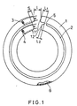
- FIG. 1 is a partially cutaway view in elevation of the circular fluorescent lamp of Example 1 of this invention.
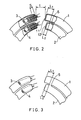
- FIG. 2 is a partially cutaway view in elevation to show the structure around the bridge-jointed portion of the circular fluorescent lamp of FIG. 1.
- FIG. 3 is an elevational view to show the structure around a circular fluorescent lamp manufactured to be compared with that of Example 1.
- FIG. 4 is an elevational view to show another structure around the bridge-jointed portion of the circular fluorescent lamp of Example 1 of this invention.
- FIG. 5 is an elevational view to show the structure around the bridge-jointed portion of a circular fluorescent lamp manufactured in Example 1 to be compared with that shown in FIG. 4.
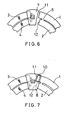
- FIG. 6 is an elevational view to show a structure around the bridge-jointed portion of the circular fluorescent lamp of Example 3 of this invention.
- FIG. 7 is an elevational view to show another structure around the bridge-jointed portion of the circular fluorescent lamp of Example 3 of this invention.
- FIG. 8 is an elevational view to show the structure around the bridge-jointed portion of a circular fluorescent lamp manufactured as a comparative example to the lamps shown in FIGs. 6 and 7 in Example 3 of this invention.
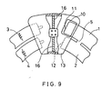
- FIG. 9 is a partially cutaway view in elevation to show the structure around the bridge-jointed portion of the circular fluorescent lamp of Example 4 of this invention.
- FIG. 10 is a partially cutaway view in elevation to show a structure of the circular fluorescent lamp of Example 5 of this invention.
- FIG. 11 is a partially cutaway view in elevation to show another structure of the circular fluorescent lamp of Example 5 of this invention.
- FIG. 12 is a partially cutaway view in elevation of a circular fluorescent lamp of Example 6 of this invention.
- FIG. 13 is a partially cutaway view in elevation to show the structure around the bridge-jointed portion of the circular fluorescent lamp shown in FIG. 12.
- FIG. 14 is an elevational view to show the structure around a circular fluorescent lamp manufactured to be compared with the ones of Examples 7 and 8.
- FIG. 15 is an elevational view to show a structure around the bridge-jointed portion of the circular fluorescent lamp of Example 7 of this invention.
- FIG. 16 is an elevational view to show another structure around the bridge-jointed portion of the circular fluorescent lamp of Example 7 of this invention.
- FIG. 17 is a partially cutaway view in elevation to show a structure around the bridge-jointed portion of the circular fluorescent lamp of Example 8 of this invention.
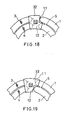
- FIG. 18 is an elevational view to show a structure around the bridge-jointed portion of the circular fluorescent lamp of Example 9 of this invention.
- FIG. 19 is an elevational view to show another structure around the bridge-jointed portion of the circular fluorescent lamp of Example 9 of this invention.
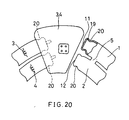
- FIG. 20 is a partially cutaway view in elevation to show a structure of the circular fluorescent lamp of Example 10 of this invention.
- FIG. 21 is a partially cutaway view in elevation to show another structure of the circular fluorescent lamp of Example 10 of this invention.
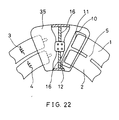
- FIG. 22 is a partially cutaway view in elevation to show a structure of the circular fluorescent lamp of Example 11 of this invention.
- FIG. 23 is a partially cutaway view in elevation to show a structure of the circular fluorescent lamp of Example 12 of this invention.
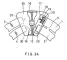
- FIG. 24 is a partially cutaway view in elevation to show another structure of the circular fluorescent lamp of Example 12 of this invention.
- FIG. 25 is a partially cutaway view in elevation of a conventional circular fluorescent lamp.
- FIG. 1 is a partially cutaway view in elevation of the circular fluorescent lamp of Example 1 of this invention
- FIG. 2 is a partially cutaway view in elevation to show the structure around the bridge-jointed portion of the circular fluorescent lamp of FIG. 1.
- the two glass circular arc tubes (1, 2) are disposed concentrically on the same plane, and at the tube-end parts of the circular arc tubes (1, 2) electrodes (3, 4) are respectively attached.
- Each of the other tube-end parts (11, 12) of the tubes (1, 2) is sealed.
- the parts adjacent to the tube-end parts (11, 12) are joined with a glass tube, namely, bridge-jointed portion 5, so that a discharge path is formed between the electrodes (3, 4) inside the luminant tubes.
- the inner surfaces of the circular arc tubes (1, 2) are coated with rare earth fluorophor 6, and mercury and rare gas (200-500Pa) for starting and buffering, e.g., argon and neon, are sealed in the tubes.
- the mercury can be an amalgam alloy like zinc-mercury.
- the circular fluorescent lamp of this invention has a compact shape, in which the tube outer diameter of the circular arc tubes (1, 2) is 14mm, the circle outer diameter of the outer circular arc tube 1 is 150mm, and the circle inner diameter of the inner arc tube 2 is 90mm.
- the lamp is designed to light on at 25W of lamp power input.
- L 1 is 11mm and L 2 is 6mm.
- the distance between the centers of the both ends of the outer circular arc tube 1, which is represented as 1, is 18mm.
- a high lumen output value namely 1620lm, with a luminous color of 3000 kelvin of color temperature, was obtained.
- Temperatures of the circular arc tubes (1, 2) were measured and it was found that a coldest spot was formed on the tube-end part 11 of the outer circular arc tube 1, and the temperature of the coldest spot was 45°C. This corresponds to the best mercury vapor pressure in which almost the maximum lumen output value can be obtained when 25W is lighted up (when the room temperature is 25°C).
- FIG. 25 shows a conventional circular fluorescent lamp that was manufactured to measure characteristics of a lamp.
- the value of L 1 ' is equal to that of L 2 '.
- the distance for L 1 ' and L 2 ', that of the temperature of the coldest spots of the tips in the best region was 13mm.
- This lamp was lighted up at 25W using an inverter circuit of 50kHz as mentioned above, and the lamp lumen output was 1490lm.
- the circular fluorescent lamp of this invention (FIGs. 1 and 2) had a higher lumen output value than that of the conventional circular fluorescent lamp shown in FIG. 25, and the difference was 130lm (about 9%). Such a high value was obtained since the distance L 1 was longer than the distance L 2 .
- FIG. 3 shows a lamp in which an electrode 3 of the circular arc tube 1 and another electrode 4 of the circular arc tube 2 were disposed in parallel.
- the circular fluorescent lamp of this invention had longer effective luminous light and the lumen output value became higher, and the difference was 40lm (3%), In this case, too, the non-luminescing area became smaller and the characteristic of luminous intensity is improved, and the improvement clearly contributes to the design of the lamp.
- the tube-end parts (11, 12) of the bridge-jointed portion 5 of the circular arc tubes (1, 2) can be projected as shown in FIG. 4.
- the shape of the tube-end parts (11, 12) of the tube (1, 2) should not be asymmetric to the center axis of the tube as shown in FIG. 5, since the strength of the glass tip is significantly lowered. In any event, a tip of the tube should be processed to be symmetric to the center axis of the tube.
- a compact circular fluorescent lamp with 60W of lamp input was manufactured.
- the structure of the lamp was basically the same as that of Example 1 (FIGs. 1 and 2).
- the tube outer diameter of the circular arc tubes (1, 2) was 20mm
- the circle outer diameter of the outer circular arc tube 1 was 240mm
- the circle inner diameter of the inner circular arc tube 2 was 155mm
- the distance L 1 was 17mm
- the distance L 2 was 10mm
- the center distance 1 of the both ends of the circular arc tube 1 was 22mm.
- the lumen output values were further measured, especially varying the distance L 1 .
- L 1 the maximum lumen output value was obtained, 0.5d ⁇ L 1 ⁇ 1.3d holds, where d was the tube outer diameter of the circular arc tubes (1, 2).
- L 1 and L 2 should be L 1 ⁇ 1.3L 2 so that a coldest spot to provide the best mercury vapor pressure is securely formed on the tube-end 11 of the outer circular arc tube 1.
- This example refers to a circular fluorescent lamp which has the same structure of the lamps shown in Examples 1 and 2, except that a lamp base is attached.
- FIG. 6 is an elevational view to show a structure around the bridge-jointed portion of the circular fluorescent lamp of Example 3 of this invention
- FIG. 7 is an elevational view to show another structure around the bridge-jointed portion of the circular fluorescent lamp of Example 3 of this invention.
- FIG. 6 shows a circular fluorescent lamp in which the tube-end parts of the circular arc tubes 1 and 2 (electrodes 3, 4 side) are surrounded with a lamp base 7. The tube-end parts 11 and 12 are separated from the lamp base 7 and exposed to the open air.
- FIG. 7 shows a circular fluorescent lamp in which tube-end parts in the electrodes (3, 4) side and the other tube-ends (11, 12) are surrounded with a lamp base 8.
- a vent 10 is provided for the lamp base 8 so that the tube-end part (the coldest spot) of the outer circular arc tube 1 is exposed to the open air.
- the lamp bases 7 and 8 are attached while the tube-end part of the non-electrode side (the coldest spot) 11 of the outer circular arc tube 1 is exposed to the open air.
- the heat of the electrodes 3 and 4 will not be transferred to the tube-end part 11, so the temperature of the coldest spot does not excessively rise. Therefore, the lamp lumen output will not be lowered.
- the lamp base 8 is attached to surround both of the tube-end parts of the electrodes (3, 4) side and the other tube-end parts (11, 12), the circular arc tubes 1 and 2 can be stable and well-kept.
- a lamp base 9 is not formed with a vent, thus the tube-end part (the coldest spot) 11 of the outer circular arc tube 1 is not exposed to the open air.
- L 1 should be longer than those of Examples 1 and 2 in order to prevent the excessive temperature increase of the coldest spot at the tips of the tube-end part when a lamp is completed.
- the effective luminous length of a lamp with the lamp base 9 in FIG. 8 becomes shorter than those of lamp bases 7 and 8 in FIGs. 6 and 7, and the lamp lumen output is lowered.
- FIG. 9 is a partially cutaway view in elevation to show a structure around the bridge-jointed portion of the circular fluorescent lamp of Example 4 of this invention.
- a lamp base 13 is attached surrounding the tube-end parts of the electrode (3, 4) side and the other tube-end parts (11, 12) of the circular arc tubes (1, 2).
- the lamp base 13 is formed with a vent 10 and a thermal shielding plate 16.
- the lamp base 13 allows the tube-end part (the coldest spot) 11 of the outer circular arc tube 1 to be exposed to the open air, and the thermal shielding plate 16 shields the heat between the tube-end parts of the electrodes(3, 4) side and the other tube-end parts (11, 12).
- the thermal shielding plate 16 controls the transference of heat from the elctrodes (3, 4) to the other tube-end part 11 of the circular arc tube 1 where the coldest spots are formed.
- the thermal shielding plate 16 controls the transference of heat from the elctrodes (3, 4) to the other tube-end part 11 of the circular arc tube 1 where the coldest spots are formed.
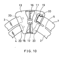
- FIG. 10 is a partially cutaway view in elevation to show a structure around the bridge-jointed portion of the circular fluorescent lamp of Example 5 of this invention.
- holding parts 20 for a bending process are provided at the outer surfaces of the both tube-end parts of the circular arc tubes 1 and 2.
- grooves 19 are formed on the inner surfaces of the tips of at least the tube-end parts (11, 12) of the non-electrode side.
- Other features are the same as those of Example 4 (FIG. 9), so the explanation is omitted.
- the holding parts 20 for the bending process can be firmly held during the lamp manufacturing process, and thus the accuracy for the bending process of the circular arc tubes (1, 2) will be improved.
- coldest spots will be formed at the grooves 19, and the temperature can be kept at the optimum level.
- the tube-end parts (11, 12) of the non-electrode side can be sealed with a stem in the same way as the tube-end parts of the electrode side.
- the strength of the tube-end parts (11, 12) will be improved compared to the case shown in FIG. 10.
- the tube-end parts are formed by partially melting the arc tubes. Therefore, tube-end parts (11, 12) of arc tubes with a larger tube diameter become thinner.
- the manufacturing method using stems to seal is relatively simple compared to the case shown in FIG. 10, and thus the tubes can be manufactured using conventional facilities.
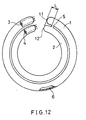
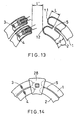
- FIG. 12 is a partially cutaway view in elevation to show the circular fluorescent lamp of Example 6 of this invention.
- FIG. 13 is a partially cutaway view in elevation to show the structure around the bridge-jointed portion of the circular fluorescent lamp shown in FIG. 12.
- FIGs. 12 and 13 show that two glass circular arc tubes (1, 2) are disposed concentrically on the same plane, and electrodes (3, 4) are attached to the tube-end parts of one side of the circular arc tubes (1, 2) respectively. The other tube-end parts (11, 12) of the circular arc tubes (1, 2) are sealed.
- the circular arc tubes 1 and 2 are joined near the tube-end parts (11, 12) with a glass bridge-jointed portion 5 in order to form a discharge path between the electrodes (3, 4) inside the arc tubes.
- Rare earth fluorophor 6 is coated on the inner surfaces of the arc tubes (1, 2).
- Mercury and rare gas (200-500Pa) as a starting-gas as well as a buffer gas (e.g., argon and neon) are sealed in the tubes.
- the mercury can be an amalgam like zinc-mercury.
- the circular fluorescent lamp of this example has a compact shape, in which the tube outer diameter of the circular arc tubes (1, 2) is 14mm, the circle outer diameter of the outer circular arc tube 1 is 150mm, and the circle inner diameter of the inner arc tube 2 is 90mm.
- the lamp is designed to light on at 25W of lamp power input.
- L is the distance measured along the center line of each of the tubes(1, 2) from the point corresponding radially to the end part of the bridge-jointed portion 5 to each of the sealed tube-end parts (11, 12).
- the center distance between the tube-end parts of the inner circular arc tube 2 is represented as 1'.
- L is 13mm and 1' is 18mm.
- This example refers to a circular fluorescent lamp which is identical to the lamp in Example 6 except that a lamp base is attached.
- a circular fluorescent lamp shown in FIG. 14 was manufactured in which the whole tube-end parts of the circular arc tubes (1, 2) are surrounded by a conventional lamp base 28, and the characteristics were measured. And it was found that the lumen output value of this lamp was 1260lm, while that value of a naked lamp without a lamp base is 1490lm. In other words, the lamp lumen output was excessively lowered, because the temperature of the coldest spots, and thus the mercury vapor pressure, rose excessively from the best region.
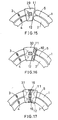
- a lamp in FIG. 15 has a lamp base 29 which is surrounding the tube-end parts of the electrodes (3, 4) side of the circular arc tubes (1, 2), while the other tube-end parts (the coldest spots) 11 and 12 are separated from the lamp base 29 and exposed to the open air.
- Another lamp in FIG. 16 has a lamp base 30 which is surrounding the tube-end parts of the electrodes (3, 4) side and the tube-end parts (11, 12) of the other side of the circular arc tube (1, 2), and the tube-end parts (11, 12) are exposed to the open air through a vent 10 formed on the lamp base 30.
- the lamp lumen output value of the lamp shown in FIG. 16 was 1520lm. Both values were approximate to that of a naked lamp without a lamp base. In other words, the lamp lumen output was not lowered so much, since the heat of the electrodes (3, 4) was not transferred to the tube-end parts (11,12), so the temperature of the coldest spots did not rise excessively from the best temperature region.
- This example refers to a circular fluorescent lamp with the rated electric power of 60W.
- the structure of the circular fluorescent lamp of this example is basically as same as that of Example 6 (see FIGs 12 and 13). And the circular fluorescent lamp of this example has a lamp base 29 which is surrounding the tube-end parts of the electrodes (3, 4) side of the circular arc tubes (1, 2), while the other tube-end parts (the coldest spots) 11, 12 are separated from the lamp base 29 to be exposed to the open air (see FIG. 15).
- the tube outer diameter of the circular arc tubes (1, 2) is 20mm
- the circle outer diameter of the outer circular arc tube 1 is 240mm
- circle inner diameter of the inner circular arc tube 2 is 155mm
- the distance L measured along the center line of each of the tubes(1, 2) from the point corresponding radially to the end part of the bridge-jointed portion 5 to each of the sealed tube-end parts (11, 12) is 19mm
- the center distance 1 of the both tube-end parts of the circular arc tube 2 is 22mm.
- a conventional lamp base 28 shown in FIG. 14 was used for the circular fluorescent lamp of this example, and further consideration was given to the structure of the lamp base 28 surrounding the whole tube-end parts of the circular arc tubes 1 and 2. Even if the whole tube-end parts of the tubes are surrounded by the lamp base, it is possible to prevent the temperature of the coldest spots from rising excessively from the best region.
- a lamp base which is formed with a thermal shielding plate 16 made of a thermal shielding part to shield the electrode side from the other tube-end parts is used. (see FIG. 17). Then, the transference of heat from the tube-end parts of the electrode (3, 4) side to the coldest spots (the other tube-end parts 11, 12) is controlled, and the lamp lumen output is not lowered.
- the lamp lumen output value was 1260lm when the lamp base 28 of FIG. 13 was used, while the value was 1420lm when the lamp base 31 with the thermal shielding plane 16 was used. A similar thermal shielding effect was obtained when the lamp base 30 with the vent 16 of FIG. 16 was used. Specifically, the lamp lumen output value was 1520lm as mentioned above when the lamp base 30 with only the vent 10 was used. But the value was 1560lm (40lm higher) when a thermal shielding plate was further provided.
- FIG. 18 is an elevational view to show a structure around the bridge-jointed portion of the circular fluorescent lamp of Example 9 of this invention.
- FIG. 19 is an elevational view to show another structure around the bridge-jointed portion of the circular fluorescent lamp of Example 9 of this invention.
- circular fluorescent lamps having lamp bases (32, 33) respectively were manufactured. Either tube-end part 11 or 12 of the circular arc tubes 1 is exposed to the open air from the lamp base 32 or 33, and a coldest spot was formed on the exposed tube-end part (11 or 12).
- the lamp lumen output of this example was as same as that of the tubes with the lamp base 29 shown in FIG. 15.
- the coldest spot is formed at the tube-end part 11 of the outer circular arc tube 1 as shown in FIG. 18, since the non-luminous area becomes smaller and a higher lamp lumen output value can be obtained.
- FIG. 20 is a partially cutaway view in elevation to show a structure around the bridge-joint portion of the circular fluorescent lamp of Example 10 of this invention.
- holding parts (20) for a bending process are provided on the outer surfaces of the both tube-end parts of the circular arc tubes 1 and 2.
- grooves 19 are formed on the inner surfaces of the tips of at least the tube-end parts (11, 12) of the non-electrode side of the tubes 1 and 2.
- the tube-end parts of the electrodes (3, 4) side of the circular arc tubes (1, 2) are surrounded with a lamp base 34, while the other tube-end parts (11, 12) are separated from the lamp base 34 and exposed to the open air.
- the holding parts 20 for the bending process can be held securely during the manufacturing process, and thus the accuracy for bending process is improved.
- coldest spots are formed at the grooves 19, and the temperature can be kept at the best value.
- the tube-end parts (11, 12) of the non-electrode side can be sealed with a stem in the same way as the tube-end parts of the electrode side.
- the strength of the tube-end parts (11, 12) will be improved compared to the case shown in FIG. 20.
- the tube-end parts are formed by partially melting the arc tubes. Therefore, tube-end parts (11, 12) of arc tubes with a larger tube diameter become thinner.
- stems some problems like cracks of the tube-end parts can be prevented during the bending process and after the lamp is completed.
- the manufacturing method using stems to seal is relatively simple compared to the case shown in FIG. 20, and thus the tubes can be manufactured using conventional facilities.
- the lamp base 34 surrounds only the tube-end parts of one side of the circular arc tubes 1 and 2.
- this example does not limit the structure of the lamp base, so any lamp base with at least tube-end parts (11, 12) exposed to the open air can be used.
- FIG. 22 is a partially cutaway view in elevation to show a structure around the bridge-jointed portion of the circular fluorescent lamp of Example 11 of this invention.
- a lamp base 35 is provided to surround the tube-end parts of the electrodes (3, 4) side and the coldest spots of the tube-end parts (11, 12) of the non-electrode side.
- a vent 10 and a thermal shielding plate 16 are provided for the lamp base 35.
- the vent 10 allows the coldest spot to be exposed to the open air, and the thermal shielding plate 16 shielded the heat between the tube-end parts of the electrode (3, 4) side and the other tube-end parts (11, 12).
- this structure it is possible to prevent the temperature of the coldest spots from excessively rising from the best temperature region, because of the synergistic effect of the vent 10 and the thermal shielding plate 16. As a result, the lamp lumen output will not be lowered.
- FIG. 23 is a partially cutaway view in elevation to show a structure around the bridge-jointed portion of the circular fluorescent lamp of Example 12 of this invention.
- holding parts 20 for bending process are provided to the outer surfaces of the both tube-end parts of the circular arc tubes 1 and 2.
- grooves 19 are formed on the inner surfaces of the tips of at least the tube-end parts (11, 12) of the non-electrode side of the tubes 1 and 2.
- Other features are the same as those of Example 11 (FIG. 22), so the explanation is omitted.
- coldest spots are formed on the grooves 19 and the temperature is kept at the best value.
- the holding parts 20 for bending process can be held during the manufacturing process, and thus the accuracy for the bending process is improved.
- the tube-end parts (11, 12) of the non-electrode side are sealed with stems in the same way as the tube-end parts of the electrode side, the strength of the tube-end parts (11, 12) will be improved compared to the case shown in FIG. 23.
- the tube-end parts are formed by partially melting the arc tubes. Therefore, tube-end parts (11, 12) of arc tubes with a larger tube diameter become thinner.
- the tube-end parts are sealed with stems, some problems like cracks of the tube-end parts can be prevented during the bending process and after the lamp is completed.
- the manufacturing method using stems to seal is relatively simple compared to the case shown in FIG. 23, and thus the tubes can be manufactured using conventional facilities.
Landscapes
- Vessels And Coating Films For Discharge Lamps (AREA)
- Common Detailed Techniques For Electron Tubes Or Discharge Tubes (AREA)
Description
- This invention relates to a circular fluorescent lamp wherein plural circular arc tubes are concentrically disposed.
- JP-A-06 203 798 (Patent abstracts of Japan vol. 018, no. 551 (E-1619)) describes a circular fluorescent lamp, which has two circular arc tubes disposed concentrically and in one plane. Each of the tubes has an electrode at one tube-end part and a sealed portion at the other tube-end part, and the tubes are joined near the sealed portion with a bridge-jointed portion to form a discharge path inside the tubes. The outer tube is longer than the inner tube.
- The Philips Compact Lighting catalogue 1981, page 140 shows compact low-pressure mercury discharge lamps consisting of two straight parallel tubes each having a sealed portion at the tube-end part opposite the tube-end parts with the electrodes. The tubes are joined near the sealed end portion to form one discharge path inside the tubes.
- Circular fluorescent lamps have been commonly used, mainly for residential lightings. In order to obtain higher output power, at least two circular fluoresent lamps are disposed unevenly for a specialized lighting equipment. Such lighting equipments would become thicker and bigger, so it is not economical. Another problem is that the designing of the appliances will be limited. In another case, a circular fluorescent lamp is used and the output of the lamp is as high as the sum of the above-mentioned plural circular fluorescent lamps. However, the circular fluorescent lamp and the equipment become bigger, and economical and design problems will also occur.
- In order to solve these problems of the conventional circular fluorescent lamps, Published Unexamined (Kokai) Japanese Patent Application No. Hei 2-61956, and No. Hei 6-203798 disclose circular fluorescent lamps respectively. Such circular fluorescent lamps are manufactured by disposing two compact glass
circular arc tubes portion 23 and forming a discharging path inside the tubes (see FIG. 25). In the FIG. 25,numbers - In order to solve the above-mentioned problems of conventional techniques, this invention provides a compact, efficient and well-designed circular fluorescent lamp with high output power. The circular fluorescent lamp of this invention also has less non-luminous area and good characteristics of luminous intensity distribution, and keeps a high level of lamp lumen output around the lamp circumference.
- In order to achieve the purposes, a first circular fluorescent lamp of this invention has plural circular arc tubes disposed concentrically, and each of the tubes has an electrode at one tube-end part and a sealed portion at the other tube-end part. The tubes are joined near the sealed portion with a bridge-jointed portion, and thus a discharge path is formed inside the tubes. The distances L1 (mm) and L2 (mm) are measured along the center lines of the outer and inner tubes, respectively from the outer end of the respective circular tube to the intersection point of the centre line with a plane perpendicular to the center lines and tangential to the outer wall surface of the bridge-jointed portion on the tube end side, and L1 is longer than L2 and L1 ≧ 1.3 L2 holds true. A coldest spot to provide the best mercury vapor pressure can be accurately formed at the tip of the bridge-jointed portion side of the outer circular are tube.
- It is preferable in this circular fluorescent lamp that the plural circular arc tubes are disposed on the same plane.
- It is also preferable that 0.5 d ≦ L1 ≦ 1.3 d holds true.
- It is also preferable that the tube-end part of the electrode side of the outer circular arc tube is longer than that of the inner circular arc tube.
- It is also preferable that the configuration of the tips of the bridge-jointed portions are essentially symmetric to the center axis of the circular arc tubes.
- It is also preferable that holding parts for a bending process are provided at the outer surfaces of the both tube-end parts of the circular arc tubes. Preferably in this case, grooves are formed on at least the inner surfaces of the tips of the non-electrode side.
- It is also preferable that a lamp base is provided to surround the tube-end parts of the electrode side of the circular arc tubes.
- It is also preferable that a lamp base is provided to surround the both tube-end parts of the circular arc tubes while the tube-end part of the non-electrode side of the outer arc tube is exposed to the open air. Preferably in this case, a thermal shielding part is provided with the lamp base in order to shield the heat between the tube-end parts of the electrode side and the tube-end parts of the non-electrode side.
- It is also preferable that the tube-end parts of the non-electrode side of the circular arc tubes are sealed with stems.
- According to a second embodiment, a circular fluorescent lamp of this invention has plural circular arc tubes disposed concentrically, and each of the tubes has an electrode at one tube-end part, and a sealed portion at the other tube-end part. The tubes are joined near the sealed portions with a bridge-jointed portion to form one discharge path inside the tubes, and a coldest spot is formed at the other tube-end part of the non-electrode side. When the distance L(mm) is measured along the center line of the tube from the outer end of the respective circular tube to the intersecting point of the centre line with a plane perpendicular to the centre line and tangential to the outer wall surface of the bridge-jointed portion on the tube-end side, and the tube outer diameter of the arc tube is d(mm), 0.5d≦L≦1.3d holds true.
- It is preferable in this second embodiment that the plural arc tubes are disposed on the same plane.
- It is also preferable that holding parts for a bending process are provided at the outer surfaces of the both tube-end parts of the circular luminous tubes. Preferably in this case, grooves are formed at least at the inner surfaces of the tips of the non-electrode side.
- It is also preferable that the non-electrode tube-end parts of the circular arc tubes are sealed with stems.
- According to the first embodiment, the circular fluorescent lamp has plural arc tubes disposed concentrically, and each of the tubes has an electrode at one end part and a sealed portion of the other tube-end part. The tubes are joined near the tube-end parts of the non-electrode side to form a discharge path inside the tubes with the bridge-jointed portion. The distances L1 (mm) and L2 (mm) measured as shown in fig.2, are such that L1 is longer than L2. Therefore, a coldest spot is formed on the end part of the non-electrode side of the outer circular arc tube. In addition, the temperature can be easily controlled to provide the best mercury vapor pressure which is corresponding to the maximum value of the lamp lumen output.
- And according to the preferable example of the first embodiment in which- the plural circular arc tubes are disposed on the same plane, the lighting equipment can be thinner.
- According to the preferable example of the first embodiment in which the tube-end part of the electrode side of the outer circular arc tube is longer than that of the inner circular arc tube, the effective luminous length becomes longer and as a result, lamp lumen output can be increased. In addition, if the effective luminous length of the circular arc tube is longer, the non-luminous area of the circular fluorescent lamp becomes smaller. Therefore, the characteristics of the luminous intensity distribution can be improved and a compact and well-designed circular fluorescent lamp can be provided.
- According to the preferable example of the first embodiment in which the configurations of the tips of the bridge-jointed portion side are essentially symmetric to the center axis of the circular arc tube, the strength of the tip of the bridge-jointed portion side will not be lowered.
- According to the preferable example of the first embodiment in which holding parts for a bending process are provided at the outer surfaces of the both tube-end parts of the circular arc tubes, the holding parts for a bending process of the circular arc tubes can be held securely while manufacturing a lamp. Therefore, the bending accuracy of the circular arc tubes can be improved. In addition, according to the preferable example in which grooves are formed at least at the inner surfaces of the tips of the non-electrode side, the coldest spots are formed in the grooves to keep the temperature at the best level.
- According to the preferable example of the first embodiment in which a lamp base is provided to surround the tube-end parts of the electrode side of the circular arc tubes, the heat of the electrodes is not transferred to the other tube-end parts of the non-electrode side, so the temperature of the coldest spot does not rise excessively from the best temperature region, and therefore, the lamp lumen output is not lowered.
- According to the preferable example of the first embodiment in which a lamp base is provided to surround the both tube-end parts of the circular arc tubes and those of the non-electrode side, and the tube-end part of the outer circular arc is exposed to the open air, the plural circular arc tubes can be securely held. In addition, the temperature of the coldest spot does not excessively rise. As a result, the lamp lumen output will not be lowered. And according to the preferable example in which a thermal shielding part is provided in order to shield the heat between the tube-end parts of the electrode side and those of the non-electrode side, transference of heat from the electrodes to the tube-end parts of the other side where the coldest spot is formed can be controlled. As a result, it is possible to prevent the excessive rise of the temperature of the coldest spot more securely, so the lamp lumen output will not be lowered.
- According to the preferable example of the first embodiment of this invention, in which the tube-end parts of the non-electrode side of the circular arc tubes are sealed with stems, the strength of the tube-end parts of the non-electrode sides is improved compared to that of the conventional tubes. Conventionally, tube-end parts are formed by partially melting arc tubes. If the diameter of the arc tube is large, the tube-end parts of the non-electrode side become thin. On the other hand, the tube-end parts can be securely sealed by stems and also, inconvenience like cracking of the tube-end parts will be prevented during the tube bending process and after the lamp is completed. In addition, the process of manufacturing by sealing with stems is simple compared to that of the prior art, and thus the arc tubes of this invention can be manufactured using the conventional facilities.
- The circular fluorescent lamp of the second embodiment of this invention has plural circular arc tubes disposed concentrically, and each of the tubes has an electrode at one tube-end part and a sealed portion of the other tube-end. And the tubes are joined near the other tube-end parts with the bridge-jointed portion to form a discharge path inside the tubes while coldest spots are formed at the tube-end parts of the non-electrode parts. The distance L(mm), measured in the same way as L1 or L2 previously mentioned, and the outer diameter of the circular arc tube d(mm) satisfy the relationship 0.5d≦L≦1.3d. Therefore, the temperature of the coldest spots can be kept in the region where the mercury vapor pressure in the arc tube is the best, and the maximum value of the lamp lumen output can be easily obtained.
- FIG. 1 is a partially cutaway view in elevation of the circular fluorescent lamp of Example 1 of this invention.
- FIG. 2 is a partially cutaway view in elevation to show the structure around the bridge-jointed portion of the circular fluorescent lamp of FIG. 1.
- FIG. 3 is an elevational view to show the structure around a circular fluorescent lamp manufactured to be compared with that of Example 1.
- FIG. 4 is an elevational view to show another structure around the bridge-jointed portion of the circular fluorescent lamp of Example 1 of this invention.
- FIG. 5 is an elevational view to show the structure around the bridge-jointed portion of a circular fluorescent lamp manufactured in Example 1 to be compared with that shown in FIG. 4.
- FIG. 6 is an elevational view to show a structure around the bridge-jointed portion of the circular fluorescent lamp of Example 3 of this invention.
- FIG. 7 is an elevational view to show another structure around the bridge-jointed portion of the circular fluorescent lamp of Example 3 of this invention.
- FIG. 8 is an elevational view to show the structure around the bridge-jointed portion of a circular fluorescent lamp manufactured as a comparative example to the lamps shown in FIGs. 6 and 7 in Example 3 of this invention.
- FIG. 9 is a partially cutaway view in elevation to show the structure around the bridge-jointed portion of the circular fluorescent lamp of Example 4 of this invention.
- FIG. 10 is a partially cutaway view in elevation to show a structure of the circular fluorescent lamp of Example 5 of this invention.
- FIG. 11 is a partially cutaway view in elevation to show another structure of the circular fluorescent lamp of Example 5 of this invention.
- FIG. 12 is a partially cutaway view in elevation of a circular fluorescent lamp of Example 6 of this invention.
- FIG. 13 is a partially cutaway view in elevation to show the structure around the bridge-jointed portion of the circular fluorescent lamp shown in FIG. 12.
- FIG. 14 is an elevational view to show the structure around a circular fluorescent lamp manufactured to be compared with the ones of Examples 7 and 8.
- FIG. 15 is an elevational view to show a structure around the bridge-jointed portion of the circular fluorescent lamp of Example 7 of this invention.
- FIG. 16 is an elevational view to show another structure around the bridge-jointed portion of the circular fluorescent lamp of Example 7 of this invention.
- FIG. 17 is a partially cutaway view in elevation to show a structure around the bridge-jointed portion of the circular fluorescent lamp of Example 8 of this invention.
- FIG. 18 is an elevational view to show a structure around the bridge-jointed portion of the circular fluorescent lamp of Example 9 of this invention.
- FIG. 19 is an elevational view to show another structure around the bridge-jointed portion of the circular fluorescent lamp of Example 9 of this invention.
- FIG. 20 is a partially cutaway view in elevation to show a structure of the circular fluorescent lamp of Example 10 of this invention.
- FIG. 21 is a partially cutaway view in elevation to show another structure of the circular fluorescent lamp of Example 10 of this invention.
- FIG. 22 is a partially cutaway view in elevation to show a structure of the circular fluorescent lamp of Example 11 of this invention.
- FIG. 23 is a partially cutaway view in elevation to show a structure of the circular fluorescent lamp of Example 12 of this invention.
- FIG. 24 is a partially cutaway view in elevation to show another structure of the circular fluorescent lamp of Example 12 of this invention.
- FIG. 25 is a partially cutaway view in elevation of a conventional circular fluorescent lamp.
- This invention will be explained in detail with reference to the attached figures and the following examples.
- FIG. 1 is a partially cutaway view in elevation of the circular fluorescent lamp of Example 1 of this invention, and FIG. 2 is a partially cutaway view in elevation to show the structure around the bridge-jointed portion of the circular fluorescent lamp of FIG. 1. As shown in these figures, the two glass circular arc tubes (1, 2) are disposed concentrically on the same plane, and at the tube-end parts of the circular arc tubes (1, 2) electrodes (3, 4) are respectively attached. Each of the other tube-end parts (11, 12) of the tubes (1, 2) is sealed. The parts adjacent to the tube-end parts (11, 12) are joined with a glass tube, namely, bridge-jointed
portion 5, so that a discharge path is formed between the electrodes (3, 4) inside the luminant tubes. The inner surfaces of the circular arc tubes (1, 2) are coated withrare earth fluorophor 6, and mercury and rare gas (200-500Pa) for starting and buffering, e.g., argon and neon, are sealed in the tubes. The mercury can be an amalgam alloy like zinc-mercury. - The circular fluorescent lamp of this invention has a compact shape, in which the tube outer diameter of the circular arc tubes (1, 2) is 14mm, the circle outer diameter of the outer
circular arc tube 1 is 150mm, and the circle inner diameter of theinner arc tube 2 is 90mm. The lamp is designed to light on at 25W of lamp power input. - L1 is 11mm and L2 is 6mm. The distance between the centers of the both ends of the outer
circular arc tube 1, which is represented as 1, is 18mm. When the circular fluorescent lamp was lighted up at 25W using an inverter circuit of 50kHz, a high lumen output value, namely 1620lm, with a luminous color of 3000 kelvin of color temperature, was obtained. Temperatures of the circular arc tubes (1, 2) were measured and it was found that a coldest spot was formed on the tube-end part 11 of the outercircular arc tube 1, and the temperature of the coldest spot was 45°C. This corresponds to the best mercury vapor pressure in which almost the maximum lumen output value can be obtained when 25W is lighted up (when the room temperature is 25°C). - FIG. 25 shows a conventional circular fluorescent lamp that was manufactured to measure characteristics of a lamp. The value of L1' is equal to that of L2'. According to this lamp, the distance for L1' and L2', that of the temperature of the coldest spots of the tips in the best region was 13mm. This lamp was lighted up at 25W using an inverter circuit of 50kHz as mentioned above, and the lamp lumen output was 1490lm. In other words, the circular fluorescent lamp of this invention (FIGs. 1 and 2) had a higher lumen output value than that of the conventional circular fluorescent lamp shown in FIG. 25, and the difference was 130lm (about 9%). Such a high value was obtained since the distance L1 was longer than the distance L2. Thus a coldest spot was formed at the tube-
end part 11 of the non-electrode side of the outercircular arc tube 1, and the temperature was easily controlled to be the best mercury vapor pressure which corresponded to the maximum value of the lamp lumen output. And compared to the prior art of FIG.25, the circular fluorescent lamp of this invention had less area which did not luminesce. Therefore, the characteristic of the luminous intensity distribution along the circular circumference was improved, and the improvement also contributed to the design of the lamp. - As shown in FIGs. 1 and 2, the electrode tube-end part of the outer
circular arc tube 1 is displaced to be longer than that of the innercircular arc tube 2. In other words, the difference between the length of the tubes is represented as S. For reference, another lamp was manufactured to measure the characteristics of the lamps. FIG. 3 shows a lamp in which anelectrode 3 of thecircular arc tube 1 and anotherelectrode 4 of thecircular arc tube 2 were disposed in parallel. When the lamp was lighted up at 25W of lamp input power using an inverter circuit of 50kHz, the lamp lumen output was 1580lm. In other words, the circular fluorescent lamp of this invention had longer effective luminous light and the lumen output value became higher, and the difference was 40lm (3%), In this case, too, the non-luminescing area became smaller and the characteristic of luminous intensity is improved, and the improvement clearly contributes to the design of the lamp. - The tube-end parts (11, 12) of the bridge-jointed
portion 5 of the circular arc tubes (1, 2) can be projected as shown in FIG. 4. The shape of the tube-end parts (11, 12) of the tube (1, 2) should not be asymmetric to the center axis of the tube as shown in FIG. 5, since the strength of the glass tip is significantly lowered. In any event, a tip of the tube should be processed to be symmetric to the center axis of the tube. - In this example, a compact circular fluorescent lamp with 60W of lamp input was manufactured. The structure of the lamp was basically the same as that of Example 1 (FIGs. 1 and 2). The tube outer diameter of the circular arc tubes (1, 2) was 20mm, the circle outer diameter of the outer
circular arc tube 1 was 240mm, the circle inner diameter of the innercircular arc tube 2 was 155mm, the distance L1 was 17mm, the distance L2 was 10mm, and thecenter distance 1 of the both ends of thecircular arc tube 1 was 22mm. When the lamp was lighted up at 60W of lamp input using an inverter circuit of 50kHz, a high lumen output value (4530lm) was obtained. - Related to the lamps of Examples 1 and 2, the lumen output values were further measured, especially varying the distance L1. When the maximum lumen output value was obtained, 0.5d≦L1≦1.3d holds, where d was the tube outer diameter of the circular arc tubes (1, 2). And it was found out that the relation between L1 and L2 should be L1≧1.3L2 so that a coldest spot to provide the best mercury vapor pressure is securely formed on the tube-
end 11 of the outercircular arc tube 1. - This example refers to a circular fluorescent lamp which has the same structure of the lamps shown in Examples 1 and 2, except that a lamp base is attached.
- FIG. 6 is an elevational view to show a structure around the bridge-jointed portion of the circular fluorescent lamp of Example 3 of this invention, and FIG. 7 is an elevational view to show another structure around the bridge-jointed portion of the circular fluorescent lamp of Example 3 of this invention. FIG. 6 shows a circular fluorescent lamp in which the tube-end parts of the
circular arc tubes 1 and 2 (electrodes lamp base 7. The tube-end parts lamp base 7 and exposed to the open air. On the other hand, FIG. 7 shows a circular fluorescent lamp in which tube-end parts in the electrodes (3, 4) side and the other tube-ends (11, 12) are surrounded with alamp base 8. In this case, avent 10 is provided for thelamp base 8 so that the tube-end part (the coldest spot) of the outercircular arc tube 1 is exposed to the open air. As mentioned above, thelamp bases circular arc tube 1 is exposed to the open air. The heat of theelectrodes end part 11, so the temperature of the coldest spot does not excessively rise. Therefore, the lamp lumen output will not be lowered. Especially, when thelamp base 8 is attached to surround both of the tube-end parts of the electrodes (3, 4) side and the other tube-end parts (11, 12), thecircular arc tubes - In FIG. 8, a
lamp base 9 is not formed with a vent, thus the tube-end part (the coldest spot) 11 of the outercircular arc tube 1 is not exposed to the open air. When thislamp base 9 is used to surround the both tube-end parts of thecircular arc tubes lamp base 9 in FIG. 8 becomes shorter than those oflamp bases - FIG. 9 is a partially cutaway view in elevation to show a structure around the bridge-jointed portion of the circular fluorescent lamp of Example 4 of this invention. As shown in FIG. 9, a
lamp base 13 is attached surrounding the tube-end parts of the electrode (3, 4) side and the other tube-end parts (11, 12) of the circular arc tubes (1, 2). Thelamp base 13 is formed with avent 10 and athermal shielding plate 16. Thelamp base 13 allows the tube-end part (the coldest spot) 11 of the outercircular arc tube 1 to be exposed to the open air, and thethermal shielding plate 16 shields the heat between the tube-end parts of the electrodes(3, 4) side and the other tube-end parts (11, 12). Thethermal shielding plate 16 controls the transference of heat from the elctrodes (3, 4) to the other tube-end part 11 of thecircular arc tube 1 where the coldest spots are formed. Thus it is possible to prevent the temperature of the coldest spot from rising excessively above the best temperature region more securely compared to the case of Example 3. As a result, the lamp lumen output will not be lowered. - FIG. 10 is a partially cutaway view in elevation to show a structure around the bridge-jointed portion of the circular fluorescent lamp of Example 5 of this invention. As shown in FIG. 10, holding
parts 20 for a bending process are provided at the outer surfaces of the both tube-end parts of thecircular arc tubes grooves 19 are formed on the inner surfaces of the tips of at least the tube-end parts (11, 12) of the non-electrode side. Other features are the same as those of Example 4 (FIG. 9), so the explanation is omitted. According to this structure, the holdingparts 20 for the bending process can be firmly held during the lamp manufacturing process, and thus the accuracy for the bending process of the circular arc tubes (1, 2) will be improved. In addition, coldest spots will be formed at thegrooves 19, and the temperature can be kept at the optimum level. - As shown in FIG. 11, the tube-end parts (11, 12) of the non-electrode side can be sealed with a stem in the same way as the tube-end parts of the electrode side. Thus the strength of the tube-end parts (11, 12) will be improved compared to the case shown in FIG. 10. In FIG. 10, the tube-end parts are formed by partially melting the arc tubes. Therefore, tube-end parts (11, 12) of arc tubes with a larger tube diameter become thinner. On the other hand, if the tube-end parts are sealed with stems, some problems like cracks of the tube-end parts can be prevented during the bending process and after the lamp is completed. In addition, the manufacturing method using stems to seal is relatively simple compared to the case shown in FIG. 10, and thus the tubes can be manufactured using conventional facilities.
- FIG. 12 is a partially cutaway view in elevation to show the circular fluorescent lamp of Example 6 of this invention. FIG. 13 is a partially cutaway view in elevation to show the structure around the bridge-jointed portion of the circular fluorescent lamp shown in FIG. 12. FIGs. 12 and 13 show that two glass circular arc tubes (1, 2) are disposed concentrically on the same plane, and electrodes (3, 4) are attached to the tube-end parts of one side of the circular arc tubes (1, 2) respectively. The other tube-end parts (11, 12) of the circular arc tubes (1, 2) are sealed. The
circular arc tubes portion 5 in order to form a discharge path between the electrodes (3, 4) inside the arc tubes.Rare earth fluorophor 6 is coated on the inner surfaces of the arc tubes (1, 2). Mercury and rare gas (200-500Pa) as a starting-gas as well as a buffer gas (e.g., argon and neon) are sealed in the tubes. The mercury can be an amalgam like zinc-mercury. - The circular fluorescent lamp of this example has a compact shape, in which the tube outer diameter of the circular arc tubes (1, 2) is 14mm, the circle outer diameter of the outer
circular arc tube 1 is 150mm, and the circle inner diameter of theinner arc tube 2 is 90mm. The lamp is designed to light on at 25W of lamp power input. - L is the distance measured along the center line of each of the tubes(1, 2) from the point corresponding radially to the end part of the bridge-jointed
portion 5 to each of the sealed tube-end parts (11, 12). The center distance between the tube-end parts of the innercircular arc tube 2 is represented as 1'. L is 13mm and 1' is 18mm. When the circular fluorescent lamp was lighted up at 25W using an inverter circuit of 50kHz, a high lumen output value, namely 1490lm, with luminous color of 3000 kelvin of color temperature was obtained. Temperatures of the circular arc tubes (1, 2) were measured and the coldest spots were found to be formed on the tube-end parts (11, 12). The temperatures of the coldest spots were 45°C. This corresponds to the best mercury vapor pressure in which almost the maximum lumen output value can be obtained when 25W is lighted up (when the room temperature is 25°C). After various examinations, it was found that the distance L should be limited to 0.5d≦L≦1.3d where the tube outer diameter is represented as d. As a result, the temperature of the coldest spots was kept in a region where the mercury vapor pressure inside the arc tubes is best, and the maximum value of the lamp lumen output was easily obtained. - This example refers to a circular fluorescent lamp which is identical to the lamp in Example 6 except that a lamp base is attached.
- A circular fluorescent lamp shown in FIG. 14 was manufactured in which the whole tube-end parts of the circular arc tubes (1, 2) are surrounded by a
conventional lamp base 28, and the characteristics were measured. And it was found that the lumen output value of this lamp was 1260lm, while that value of a naked lamp without a lamp base is 1490lm. In other words, the lamp lumen output was excessively lowered, because the temperature of the coldest spots, and thus the mercury vapor pressure, rose excessively from the best region. - Based on the result, two types of circular fluorescent lamps were manufactured. A lamp in FIG. 15 has a
lamp base 29 which is surrounding the tube-end parts of the electrodes (3, 4) side of the circular arc tubes (1, 2), while the other tube-end parts (the coldest spots) 11 and 12 are separated from thelamp base 29 and exposed to the open air. Another lamp in FIG. 16 has alamp base 30 which is surrounding the tube-end parts of the electrodes (3, 4) side and the tube-end parts (11, 12) of the other side of the circular arc tube (1, 2), and the tube-end parts (11, 12) are exposed to the open air through avent 10 formed on thelamp base 30. The lamp lumen output value of the lamp shown in FIG. 15 was 1575lm, and the lamp lumen output value of the lamp shown in FIG. 16 was 1520lm. Both values were approximate to that of a naked lamp without a lamp base. In other words, the lamp lumen output was not lowered so much, since the heat of the electrodes (3, 4) was not transferred to the tube-end parts (11,12), so the temperature of the coldest spots did not rise excessively from the best temperature region. - This example refers to a circular fluorescent lamp with the rated electric power of 60W.
- The structure of the circular fluorescent lamp of this example is basically as same as that of Example 6 (see FIGs 12 and 13). And the circular fluorescent lamp of this example has a
lamp base 29 which is surrounding the tube-end parts of the electrodes (3, 4) side of the circular arc tubes (1, 2), while the other tube-end parts (the coldest spots) 11, 12 are separated from thelamp base 29 to be exposed to the open air (see FIG. 15). - The tube outer diameter of the circular arc tubes (1, 2) is 20mm, the circle outer diameter of the outer
circular arc tube 1 is 240mm, circle inner diameter of the innercircular arc tube 2 is 155mm, the distance L measured along the center line of each of the tubes(1, 2) from the point corresponding radially to the end part of the bridge-jointedportion 5 to each of the sealed tube-end parts (11, 12) is 19mm, and thecenter distance 1 of the both tube-end parts of thecircular arc tube 2 is 22mm. When this lamp was lighted up with a lamp input of 60W using an inverter circuit of 50kHz, a high lamp lumen output, namely 4390lm, was obtained. - A
conventional lamp base 28 shown in FIG. 14 was used for the circular fluorescent lamp of this example, and further consideration was given to the structure of thelamp base 28 surrounding the whole tube-end parts of thecircular arc tubes thermal shielding plate 16 made of a thermal shielding part to shield the electrode side from the other tube-end parts is used. (see FIG. 17). Then, the transference of heat from the tube-end parts of the electrode (3, 4) side to the coldest spots (the other tube-end parts 11, 12) is controlled, and the lamp lumen output is not lowered. Specifically, the lamp lumen output value was 1260lm when thelamp base 28 of FIG. 13 was used, while the value was 1420lm when the lamp base 31 with the thermal shieldingplane 16 was used. A similar thermal shielding effect was obtained when thelamp base 30 with thevent 16 of FIG. 16 was used. Specifically, the lamp lumen output value was 1520lm as mentioned above when thelamp base 30 with only thevent 10 was used. But the value was 1560lm (40lm higher) when a thermal shielding plate was further provided. - FIG. 18 is an elevational view to show a structure around the bridge-jointed portion of the circular fluorescent lamp of Example 9 of this invention. FIG. 19 is an elevational view to show another structure around the bridge-jointed portion of the circular fluorescent lamp of Example 9 of this invention.
- In this example, as shown in FIGs. 18 and 19, circular fluorescent lamps having lamp bases (32, 33) respectively were manufactured. Either tube-
end part circular arc tubes 1 is exposed to the open air from thelamp base lamp base 29 shown in FIG. 15. Preferably, the coldest spot is formed at the tube-end part 11 of the outercircular arc tube 1 as shown in FIG. 18, since the non-luminous area becomes smaller and a higher lamp lumen output value can be obtained. - FIG. 20 is a partially cutaway view in elevation to show a structure around the bridge-joint portion of the circular fluorescent lamp of Example 10 of this invention. As shown in FIG. 20, holding parts (20) for a bending process are provided on the outer surfaces of the both tube-end parts of the
circular arc tubes grooves 19 are formed on the inner surfaces of the tips of at least the tube-end parts (11, 12) of the non-electrode side of thetubes lamp base 34, while the other tube-end parts (11, 12) are separated from thelamp base 34 and exposed to the open air. According to this example, the holdingparts 20 for the bending process can be held securely during the manufacturing process, and thus the accuracy for bending process is improved. In addition, coldest spots are formed at thegrooves 19, and the temperature can be kept at the best value. - As shown in FIG. 21, the tube-end parts (11, 12) of the non-electrode side can be sealed with a stem in the same way as the tube-end parts of the electrode side. Thus the strength of the tube-end parts (11, 12) will be improved compared to the case shown in FIG. 20. In FIG. 20, the tube-end parts are formed by partially melting the arc tubes. Therefore, tube-end parts (11, 12) of arc tubes with a larger tube diameter become thinner. On the other hand, if the tube-end parts are sealed with stems, some problems like cracks of the tube-end parts can be prevented during the bending process and after the lamp is completed. In addition, the manufacturing method using stems to seal is relatively simple compared to the case shown in FIG. 20, and thus the tubes can be manufactured using conventional facilities.
- In this example, the
lamp base 34 surrounds only the tube-end parts of one side of thecircular arc tubes - FIG. 22 is a partially cutaway view in elevation to show a structure around the bridge-jointed portion of the circular fluorescent lamp of Example 11 of this invention. As shown in FIG. 22, a
lamp base 35 is provided to surround the tube-end parts of the electrodes (3, 4) side and the coldest spots of the tube-end parts (11, 12) of the non-electrode side. And avent 10 and athermal shielding plate 16 are provided for thelamp base 35. Thevent 10 allows the coldest spot to be exposed to the open air, and thethermal shielding plate 16 shielded the heat between the tube-end parts of the electrode (3, 4) side and the other tube-end parts (11, 12). According to this structure, it is possible to prevent the temperature of the coldest spots from excessively rising from the best temperature region, because of the synergistic effect of thevent 10 and thethermal shielding plate 16. As a result, the lamp lumen output will not be lowered. - FIG. 23 is a partially cutaway view in elevation to show a structure around the bridge-jointed portion of the circular fluorescent lamp of Example 12 of this invention. As shown in FIG. 20, holding
parts 20 for bending process are provided to the outer surfaces of the both tube-end parts of thecircular arc tubes grooves 19 are formed on the inner surfaces of the tips of at least the tube-end parts (11, 12) of the non-electrode side of thetubes grooves 19 and the temperature is kept at the best value. Thus it is possible to prevent temperature rise of the coldest spots more securely compared to the case of Example 11. Also, in this example, the holdingparts 20 for bending process can be held during the manufacturing process, and thus the accuracy for the bending process is improved. - As shown in FIG. 24, if the tube-end parts (11, 12) of the non-electrode side are sealed with stems in the same way as the tube-end parts of the electrode side, the strength of the tube-end parts (11, 12) will be improved compared to the case shown in FIG. 23. In FIG. 23, the tube-end parts are formed by partially melting the arc tubes. Therefore, tube-end parts (11, 12) of arc tubes with a larger tube diameter become thinner. On the other hand, if the tube-end parts are sealed with stems, some problems like cracks of the tube-end parts can be prevented during the bending process and after the lamp is completed. In addition, the manufacturing method using stems to seal is relatively simple compared to the case shown in FIG. 23, and thus the tubes can be manufactured using conventional facilities.
Claims (16)
- A circular fluorescent lamp which has two circular arc tubes (1, 2) disposed concentrically, each of the tubes has an electrode (3 or 4) at one tube-end part and a sealed portion at the other tube-end part (11 or 12), and the tubes (1, 2) are joined near the sealed portion with a bridge-jointed portion (5) to form a discharge path inside the tubes, wherein the distances L1 and L2 are measured along the centre lines of the outer and inner tubes (1, 2), respectively, from the outer end of the respective circular tube (1, 2) to the intersection point of the centre line with a plane perpendicular to the center lines and tangential to the outer wall surface of the bridge jointed portion (5) on the tube end side, and L1 is longer than L2, characterised in that L1 ≥ 1.3 L2 holds true.
- The circular fluorescent lamp according to claim 1, wherein the tube outer diameter of the arc tubes (1, 2) is d and 0.5 d ≤ L1 ≤ 1.3 d holds true.
- A circular fluorescent lamp which has two circular arc tubes (1, 2) disposed concentrically, each of the tubes (1, 2) has an electrode (3 or 4) at one tube-end part and a sealed portion at the other tube-end part, and the tubes (1, 2) are joined near the sealed portion with a bridge-jointed portion (5) to form a discharge path inside the tubes (1, 2) and coldest spots are formed at the tube-end parts (11, 12) on the non-electrode side, wherein if the distance L is measured along the centre line of the circular tube, from the outer end of the respective circular tube (1, 2) to the intersecting point of the centre line with a plane perpendicular to the centre line and tangential to the outer wall surface of the bridge jointed portion (5) on the tube end side, and the tube outer diameter of the arc tube is d, characterised in that 0.5 d ≤L ≤ 1.3 d holds true, holding means (20) for a bending process are provided at the outer surfaces of the both tube-end parts of the circular arc tubes (1, 2) and grooves (19) are provided on the inner surfaces of the tips of the both tube-end parts (11, 12) said grooves (19) forming the coldest spots.
- The circular fluorescent lamp according to any of claims 1 to 3, wherein one discharge path inside the tubes (1, 2), and coldest spots are formed at the tube-end parts (11, 12) on the non-electrode side, and the circular fluorescent lamp is also provided with a lamp base (7, 8, 13, 28, 29, 30, 31, 32, 33, 34 or 35) which surrounds at least on side of the both tube-end parts, and the coldest spots which are formed on the outer circular arc tube (1) are exposed to the open air.
- The circular fluorescent lamp according to any of claim s 1 to 4, wherein the tube-end parts (11, 12) of the non-electrode side with a bridge-jointed portion (5) to form a discharge path inside the tubes (1, 2), while coldest spots are formed at the tube-end parts (11, 12) on the non-electrode side and a lamp base (7, 8, 9, 13, 28, 29, 30, 31, 32, 33, 34 or 35) is provided to surround at least on side of the both tube-end parts (11, 12) and the thermal shielding part (16) is also provided for the lamp base (7, 8, 9, 13, 28, 29, 30, 31, 32, 33, 34 or 35) in order to shield the heat between the tube-end parts (11, 12) of the electrode side and those of the non-electrode side.
- The circular fluorescent lamp according to any of claim 1 to 5, wherein the plural circular arc tubes 81, 2) are disposed on the same plane.
- The circular fluorescent lamp according to claim 1, wherein the tube-end part of the electrode is of the outer circular are tube (1) is longer than that of the inner circular arc tube (2).
- The circular fluorescent lamp according to claim 1, wherein the configurations of the tips of the bridge-jointed portions (5) are essentially symmetric to the centre axis of the circular arc tubes (1, 2).
- The circular fluorescent lamp according to claim 8, wherein grooves (19) are formed on at least the inner surfaces of the tips of the non-electrode sides of the tubes (1, 2).
- The circular fluorescent lamp according to claim 1, wherein a lamp base (7,8 9, 13, 28, 29, 30, 31, 32, 33, 34 or 35) is provided to surround the tube-end parts of the electrode side of the circular arc tubes (1, 2).
- The circular fluorescent lamp according to claim 1, wherein that a lamp base (7, 8, 9, 13, 28, 29, 30,31, 32, 33, 34 or 35) is provided to surround the both tube-end parts of the circular arc tubes (1, 2) while the tube-end parts (11, 12) of the non-electrode side of the outer arc tube (1) are exposed to the open air.
- The circular fluorescent lamp according to claim 11, wherein a thermal shielding part (16) is provided for the lamp base (7, 8, 9, 13, 28, 29, 30, 31 ,32, 33, 34 or 35) in order to shield the heat between the tube-end parts of the electrode side and the tube-end parts (11, 12) of the non-electrode side.
- The circular fluorescent lamp according to any of claims 1 to 5, wherein the tube-end parts (11, 12) of the non-electrode side of the circular arc tubes (1, 2) are sealed with stems.
- The circular fluorescent lamp according to claim 3, wherein the lamp base (7, 8, 9, 13, 28, 29, 30, 31, 32, 33, 34 or ,5) is separated from the coldest spots of the non-electrode side.
- The circular fluorescent lamp according to any of claims 3 or 4, wherein the lamp base (7, 8, 9, 13, 28, 29, 30, 31, 32, 33, 34 or 35) surrounds the tube-end parts of the electrode side and the coldest spots of the other tube-end parts, and a vent (10) is provided on the lamp base (7, 8, 9, 13, 28, 29, 30, 31, 32, 33, 34 or 35) so that the coldest spots which formed on the outer circular arc tube (1) are exposed to the open air.
- The circular fluorescent lamp according to any of claims 3 or 4, wherein a coldest spot which formed on the outer circular arc tube (1) is exposed to the open air.
Applications Claiming Priority (6)
| Application Number | Priority Date | Filing Date | Title |
|---|---|---|---|
| JP32780994 | 1994-12-28 | ||
| JP327809/94 | 1994-12-28 | ||
| JP327810/94 | 1994-12-28 | ||
| JP32781094 | 1994-12-28 | ||
| JP32780994 | 1994-12-28 | ||
| JP32781094 | 1994-12-28 |
Publications (3)
| Publication Number | Publication Date |
|---|---|
| EP0720208A2 EP0720208A2 (en) | 1996-07-03 |
| EP0720208A3 EP0720208A3 (en) | 1997-01-15 |
| EP0720208B1 true EP0720208B1 (en) | 2003-05-02 |
Family
ID=26572648
Family Applications (1)
| Application Number | Title | Priority Date | Filing Date |
|---|---|---|---|
| EP95120469A Expired - Lifetime EP0720208B1 (en) | 1994-12-28 | 1995-12-22 | Circular fluorescent lamp |
Country Status (4)
| Country | Link |
|---|---|
| US (1) | US5723939A (en) |
| EP (1) | EP0720208B1 (en) |
| CN (4) | CN1071052C (en) |
| DE (1) | DE69530564T2 (en) |
Families Citing this family (11)
| Publication number | Priority date | Publication date | Assignee | Title |
|---|---|---|---|---|
| US5722549A (en) * | 1996-05-22 | 1998-03-03 | Osram Sylvania Inc. | Closed-loop tubular lamp envelope and method of manufacture |
| JP3135526B2 (en) * | 1997-03-31 | 2001-02-19 | 松下電子工業株式会社 | Ring fluorescent lamp |
| JP3219044B2 (en) * | 1997-03-31 | 2001-10-15 | 松下電器産業株式会社 | Ring fluorescent lamp |
| JP2000173537A (en) * | 1998-09-29 | 2000-06-23 | Toshiba Lighting & Technology Corp | Low pressure mercury vapor discharge lamp and lighting equipment |
| US6630779B1 (en) | 2000-06-01 | 2003-10-07 | General Electric Company | Fluorescent lamp with discharge tube bent substantially in plane |
| US6630780B1 (en) * | 2001-09-19 | 2003-10-07 | Technical Consumer Products, Inc. | Dual circular fluorescent lamp |
| WO2004049388A1 (en) * | 2002-11-22 | 2004-06-10 | Toshiba Lighting & Technology Corporation | Fluorescent lamp and luminaire |
| CN101764036B (en) * | 2008-12-23 | 2011-11-02 | 启耀光电股份有限公司 | lighting device |
| CN101852381A (en) * | 2009-03-31 | 2010-10-06 | 建兴电子科技股份有限公司 | A color-changing discharge lamp device |
| TWM579391U (en) | 2019-01-21 | 2019-06-11 | 和碩聯合科技股份有限公司 | Electronic device and antenna structure thereof |
| DE202020107117U1 (en) | 2020-12-10 | 2022-03-14 | Alois Kober Gmbh | lighting device |
Citations (2)
| Publication number | Priority date | Publication date | Assignee | Title |
|---|---|---|---|---|
| US4283217A (en) * | 1977-05-18 | 1981-08-11 | Osamu Kawamura | Method of forming a shaped fluorescent light bulb envelope |
| US4337414A (en) * | 1979-11-26 | 1982-06-29 | Westinghouse Electric Corp. | Compact fluorescent lamp having convoluted tubular envelope of tridimensional configuration, method of making such envelope, and lighting unit incorporating such lamp |
Family Cites Families (11)
| Publication number | Priority date | Publication date | Assignee | Title |
|---|---|---|---|---|
| US2309676A (en) * | 1939-12-12 | 1943-02-02 | Charles Melzak | Fluorescent lamp |
| US4121132A (en) * | 1977-09-28 | 1978-10-17 | Westinghouse Electric Corp. | Phosphor coating method and resulting fluorescent lamp |
| JPS58112238A (en) * | 1981-12-25 | 1983-07-04 | Toshiba Corp | Fluorescent lamp |
| GB2137017B (en) * | 1983-03-02 | 1986-12-10 | Emi Plc Thorn | Improvements in or relating to discharge lamps |
| JPS623798A (en) * | 1985-07-01 | 1987-01-09 | House Food Ind Co Ltd | Quick determination of number of aerobic microorganism and apparatus therefor |
| KR920003545B1 (en) * | 1987-07-01 | 1992-05-02 | 가부시끼가이샤 도시바 | Ring-shaped glass bulb and lamp assembly using the same |
| US4833574A (en) * | 1988-03-11 | 1989-05-23 | Galagher P Christopher J | Annular fluorescent lamp |
| JP2776840B2 (en) * | 1988-08-26 | 1998-07-16 | 株式会社日立製作所 | Fluorescent lamp |
| DE3829729A1 (en) * | 1988-09-01 | 1990-03-15 | Patent Treuhand Ges Fuer Elektrische Gluehlampen Mbh | HIGH PRESSURE DISCHARGE LAMP |
| CN2174780Y (en) * | 1992-12-25 | 1994-08-17 | 陆坚培 | Concentric circle multi-ring type energy-saving fluorescent lamp |
| JP2865267B2 (en) * | 1993-01-08 | 1999-03-08 | 朝日ナショナル照明株式会社 | Discharge lamp and lighting device using this lamp |
-
1995
- 1995-12-21 US US08/575,995 patent/US5723939A/en not_active Expired - Lifetime
- 1995-12-22 EP EP95120469A patent/EP0720208B1/en not_active Expired - Lifetime
- 1995-12-22 DE DE69530564T patent/DE69530564T2/en not_active Expired - Fee Related
- 1995-12-28 CN CN95113118A patent/CN1071052C/en not_active Expired - Lifetime
-
2000
- 2000-01-15 CN CN00100986A patent/CN1110837C/en not_active Expired - Lifetime
- 2000-01-15 CN CN00100987.7A patent/CN1124638C/en not_active Expired - Lifetime
- 2000-01-15 CN CN00100988.5A patent/CN1124637C/en not_active Expired - Lifetime
Patent Citations (2)
| Publication number | Priority date | Publication date | Assignee | Title |
|---|---|---|---|---|
| US4283217A (en) * | 1977-05-18 | 1981-08-11 | Osamu Kawamura | Method of forming a shaped fluorescent light bulb envelope |
| US4337414A (en) * | 1979-11-26 | 1982-06-29 | Westinghouse Electric Corp. | Compact fluorescent lamp having convoluted tubular envelope of tridimensional configuration, method of making such envelope, and lighting unit incorporating such lamp |
Non-Patent Citations (1)
| Title |
|---|
| Philips Compact Lighting Catalogue 1981, page 140 * |
Also Published As
| Publication number | Publication date |
|---|---|
| CN1264154A (en) | 2000-08-23 |
| CN1270410A (en) | 2000-10-18 |
| EP0720208A3 (en) | 1997-01-15 |
| CN1110837C (en) | 2003-06-04 |
| CN1270409A (en) | 2000-10-18 |
| EP0720208A2 (en) | 1996-07-03 |
| CN1124638C (en) | 2003-10-15 |
| DE69530564D1 (en) | 2003-06-05 |
| DE69530564T2 (en) | 2004-04-29 |
| CN1128896A (en) | 1996-08-14 |
| US5723939A (en) | 1998-03-03 |
| CN1124637C (en) | 2003-10-15 |
| CN1071052C (en) | 2001-09-12 |
Similar Documents
| Publication | Publication Date | Title |
|---|---|---|
| US6215254B1 (en) | High-voltage discharge lamp, high-voltage discharge lamp device, and lighting device | |
| US5841229A (en) | Amalgam support arrangement for an electrodeless discharge lamp | |
| EP0315261A1 (en) | High-pressure sodium discharge lamp | |
| US5723939A (en) | Circular fluorescent lamp | |
| US4625149A (en) | Metal vapor discharge lamp including an inner burner having tapered ends | |
| US6495960B1 (en) | Discharge lamp | |
| JPH07240184A (en) | Ceramic discharge lamp, floodlighting apparatus using the same, and method for manufacturing ceramic discharge lamp | |
| EP0381035B1 (en) | Single side-sealed metal vapor discharge lamp | |
| US6121729A (en) | Metal halide lamp | |
| US7633227B2 (en) | Discharge lamp with lamp base structure | |
| EP0042151B1 (en) | High-pressure sodium lamp | |
| EP0418877B2 (en) | Single-sealed metal vapor electric discharge lamp | |
| US6650042B2 (en) | Low-wattage fluorescent lamp | |
| JP2788621B2 (en) | Ring fluorescent lamp | |
| JP4431174B2 (en) | High pressure gas discharge lamp | |
| EP1057211B1 (en) | Electric lamp | |
| JP2791304B2 (en) | Ring fluorescent lamp | |
| EP1805786A2 (en) | Lamp | |
| EP0257830B1 (en) | High pressure sodium lamp | |
| JP3165026B2 (en) | Ring fluorescent lamp | |
| EP0441387A2 (en) | Low pressure gas discharge lamp | |
| JP2001345071A (en) | High pressure discharge lamp and lighting equipment | |
| JPH0574420A (en) | Metal vapor discharge lamp | |
| JP3344021B2 (en) | Cold cathode low pressure discharge lamp | |
| JPH0660849A (en) | Fluorescent lamp |
Legal Events
| Date | Code | Title | Description |
|---|---|---|---|
| PUAI | Public reference made under article 153(3) epc to a published international application that has entered the european phase |
Free format text: ORIGINAL CODE: 0009012 |
|
| AK | Designated contracting states |
Kind code of ref document: A2 Designated state(s): DE GB |
|
| PUAL | Search report despatched |
Free format text: ORIGINAL CODE: 0009013 |
|
| AK | Designated contracting states |
Kind code of ref document: A3 Designated state(s): DE GB |
|
| 17P | Request for examination filed |
Effective date: 19970124 |
|
| 17Q | First examination report despatched |
Effective date: 19970922 |
|
| GRAG | Despatch of communication of intention to grant |
Free format text: ORIGINAL CODE: EPIDOS AGRA |
|
| RAP1 | Party data changed (applicant data changed or rights of an application transferred) |
Owner name: MATSUSHITA ELECTRIC INDUSTRIAL CO., LTD. |
|
| GRAG | Despatch of communication of intention to grant |
Free format text: ORIGINAL CODE: EPIDOS AGRA |
|
| GRAH | Despatch of communication of intention to grant a patent |
Free format text: ORIGINAL CODE: EPIDOS IGRA |
|
| GRAG | Despatch of communication of intention to grant |
Free format text: ORIGINAL CODE: EPIDOS AGRA |
|
| GRAH | Despatch of communication of intention to grant a patent |
Free format text: ORIGINAL CODE: EPIDOS IGRA |
|
| GRAA | (expected) grant |
Free format text: ORIGINAL CODE: 0009210 |
|
| AK | Designated contracting states |
Designated state(s): DE GB |
|
| REG | Reference to a national code |
Ref country code: GB Ref legal event code: FG4D |
|
| REF | Corresponds to: |
Ref document number: 69530564 Country of ref document: DE Date of ref document: 20030605 Kind code of ref document: P |
|
| PLBE | No opposition filed within time limit |
Free format text: ORIGINAL CODE: 0009261 |
|
| STAA | Information on the status of an ep patent application or granted ep patent |
Free format text: STATUS: NO OPPOSITION FILED WITHIN TIME LIMIT |
|
| 26N | No opposition filed |
Effective date: 20040203 |
|
| PGFP | Annual fee paid to national office [announced via postgrant information from national office to epo] |
Ref country code: GB Payment date: 20051221 Year of fee payment: 11 |
|
| GBPC | Gb: european patent ceased through non-payment of renewal fee |
Effective date: 20061222 |
|
| PG25 | Lapsed in a contracting state [announced via postgrant information from national office to epo] |
Ref country code: GB Free format text: LAPSE BECAUSE OF NON-PAYMENT OF DUE FEES Effective date: 20061222 |
|
| PGFP | Annual fee paid to national office [announced via postgrant information from national office to epo] |
Ref country code: DE Payment date: 20071220 Year of fee payment: 13 |
|
| PG25 | Lapsed in a contracting state [announced via postgrant information from national office to epo] |
Ref country code: DE Free format text: LAPSE BECAUSE OF NON-PAYMENT OF DUE FEES Effective date: 20090701 |