EP0718918A1 - Connecteur avec contact à ressort et des moyens de court-circuitage - Google Patents
Connecteur avec contact à ressort et des moyens de court-circuitage Download PDFInfo
- Publication number
- EP0718918A1 EP0718918A1 EP95201380A EP95201380A EP0718918A1 EP 0718918 A1 EP0718918 A1 EP 0718918A1 EP 95201380 A EP95201380 A EP 95201380A EP 95201380 A EP95201380 A EP 95201380A EP 0718918 A1 EP0718918 A1 EP 0718918A1
- Authority
- EP
- European Patent Office
- Prior art keywords
- connector block
- contact
- contact member
- contact members
- spring
- Prior art date
- Legal status (The legal status is an assumption and is not a legal conclusion. Google has not performed a legal analysis and makes no representation as to the accuracy of the status listed.)
- Granted
Links
Images


Classifications
-
- H—ELECTRICITY
- H01—ELECTRIC ELEMENTS
- H01R—ELECTRICALLY-CONDUCTIVE CONNECTIONS; STRUCTURAL ASSOCIATIONS OF A PLURALITY OF MUTUALLY-INSULATED ELECTRICAL CONNECTING ELEMENTS; COUPLING DEVICES; CURRENT COLLECTORS
- H01R13/00—Details of coupling devices of the kinds covered by groups H01R12/70 or H01R24/00 - H01R33/00
- H01R13/02—Contact members
- H01R13/22—Contacts for co-operating by abutting
- H01R13/24—Contacts for co-operating by abutting resilient; resiliently-mounted
- H01R13/2407—Contacts for co-operating by abutting resilient; resiliently-mounted characterized by the resilient means
- H01R13/2428—Contacts for co-operating by abutting resilient; resiliently-mounted characterized by the resilient means using meander springs
-
- H—ELECTRICITY
- H01—ELECTRIC ELEMENTS
- H01R—ELECTRICALLY-CONDUCTIVE CONNECTIONS; STRUCTURAL ASSOCIATIONS OF A PLURALITY OF MUTUALLY-INSULATED ELECTRICAL CONNECTING ELEMENTS; COUPLING DEVICES; CURRENT COLLECTORS
- H01R13/00—Details of coupling devices of the kinds covered by groups H01R12/70 or H01R24/00 - H01R33/00
- H01R13/648—Protective earth or shield arrangements on coupling devices, e.g. anti-static shielding
- H01R13/6485—Electrostatic discharge protection
-
- H—ELECTRICITY
- H01—ELECTRIC ELEMENTS
- H01R—ELECTRICALLY-CONDUCTIVE CONNECTIONS; STRUCTURAL ASSOCIATIONS OF A PLURALITY OF MUTUALLY-INSULATED ELECTRICAL CONNECTING ELEMENTS; COUPLING DEVICES; CURRENT COLLECTORS
- H01R13/00—Details of coupling devices of the kinds covered by groups H01R12/70 or H01R24/00 - H01R33/00
- H01R13/66—Structural association with built-in electrical component
- H01R13/70—Structural association with built-in electrical component with built-in switch
- H01R13/703—Structural association with built-in electrical component with built-in switch operated by engagement or disengagement of coupling parts, e.g. dual-continuity coupling part
- H01R13/7031—Shorting, shunting or bussing of different terminals interrupted or effected on engagement of coupling part, e.g. for ESD protection, line continuity
- H01R13/7032—Shorting, shunting or bussing of different terminals interrupted or effected on engagement of coupling part, e.g. for ESD protection, line continuity making use of a separate bridging element directly cooperating with the terminals
-
- H—ELECTRICITY
- H01—ELECTRIC ELEMENTS
- H01R—ELECTRICALLY-CONDUCTIVE CONNECTIONS; STRUCTURAL ASSOCIATIONS OF A PLURALITY OF MUTUALLY-INSULATED ELECTRICAL CONNECTING ELEMENTS; COUPLING DEVICES; CURRENT COLLECTORS
- H01R13/00—Details of coupling devices of the kinds covered by groups H01R12/70 or H01R24/00 - H01R33/00
- H01R13/66—Structural association with built-in electrical component
- H01R13/70—Structural association with built-in electrical component with built-in switch
- H01R13/703—Structural association with built-in electrical component with built-in switch operated by engagement or disengagement of coupling parts, e.g. dual-continuity coupling part
Definitions
- the present invention relates to a connector block comprising at least one contact member, each contact member being integrally made and provided with a first contact terminal for electrical contact to a contact member of a mating electric element, a second contact terminal and a spring part giving the contact member a resilient capacity in a predetermined axial direction, the connector block also comprising a shorting rod electrically contacting predetermined contact members when the connector block is in its disconnected state and being electrically separated from said predetermined contact members when the connector block is in its connected state.
- a connector block is known from US-A-4,954,087 which is intended for test purposes and to identify electric components which are able to push away predetermined first terminals from the shorting rod in the testing state.
- the shorting rod in this prior art connector block is not intended to short circuit vulnerable electronic equipment, such as MOS elements, when the connector block is in its disconnected state. Moreover, the known shorting rod extends in an open space in the connector block and the spring parts of the contact elements occupy a large space. Thus, the design of the known connector block is unsuitable for miniaturization.
- US-A-3,903,385 shows a connector provided with opposite pairs of electrical contact members which are "shorted" by a shorting bar assembly when the connector is not connected to a printed circuit board.
- the shorting bar assembly comprises a shorting bar extending substantially perpendicular to the longitudinal direction of the contact members.
- the shorting bar is supported by a spring pushing the shorting bar against both contact members which are somewhat bent to one another for that purpose, whenever a printed circuit board is absent. Inserting a printed circuit board into the connector pushes the shorting bar away from the contact members. Since each contact member is made up of two opposite parts and each pair of contact members needs its own shorting bar with a spring the known shorting bar assembly is unsuitable for miniaturization.
- US-A-4,070,557 discloses a shroud, e.g. used in back panel systems, in which resilient bridging contact members are provided. When no connector is inserted in the shroud the bridging contact members are forced in electrical contact with preselected terminals to form a closed loop condition in vacant module positions. When a connector is inserted into the shroud the connector block pushes the bridging contact members away from the terminals, thus breaking the closed loops.
- the bridging contact members are U-shaped and need a relatively large space within the shroud making the known arrangement unsuitable for miniaturization.
- each spring part has a corrugated structure and is accommodated in a separate cavity within the connector block, the shorting rod extending within the body of the connector block and being partly exposed in predetermined cavities.
- the connector block according to the invention comprises at least one contact member, each contact member being integrally made provided with a first contact terminal for electrical contact to a contact member of a mating electric element, a second contact terminal and a spring part giving the contact member a resilient capacity in a predetermined axial direction, the connector block also comprising shorting means electrically contacting predetermined contact members when the connector block is in its disconnected state and being electrically separated from said predetermined contact members when the connector block is in its connected state characterized in that each spring part has a corrugated structure and is accommodated in a separate cavity within the connector block, the shorting means comprising at least one shorting strip extending on the surface of the body of the connector block and being exposed in predetermined cavities.
- a very thin shorting strip exposed in preselected cavities is used which also occupies very little space, thus serving the purpose of further miniaturization.
- Figure 1 shows, schematically, a hand-held telephone set known per se and comprising a telephone cradle 1 and a separate housing 4.
- the separate housing 4 may have any convenient shape, e.g. a large U-shape able to entirely accommodate the telephone cradle 1.
- the housing 4 may be fixed to a wall, a dash board of a car, etc.
- the housing 4 is made of any suitable material, e.g. plastic.
- the telephone cradle 1 can be connected to and disconnected from the housing 4.
- the telephone cradle 1 is provided with a cradle connector 2 and the housing 4 with a connector block 3.
- a hand-held telephone set must meet very demanding requirements.
- the force necessary to connect the telephone cradle to the housing 4 must be as low as possible.
- the electrical connection between the cradle connector 2 and the connector block 3 must be very reliable, even after very many connections and disconnections: the cradle connector 2 and the connector block 3 must be designed for as many connecting and disconnecting operations as at least ten thousand.
- the cradle connector 2 and the connector block 3 must be designed as small as possible. Sometimes, fifteen or more electrical connections have to be made.
- the overall dimensions of the telephone cradle 1 are largely dependent on the dimensions of the cradle connector 2 and the connector block 3. Especially, the pitch distance between neighbouring contact members in the cradle connector 2 and the connector block 3 must be as small as possible. Moreover, the thickness and the width of the cradle connector 2 and the connector block 3 have to be as small as possible. Fourthly, any operator of the telephone cradle 1 must be allowed to connect the telephone cradle 1 to the housing 4 from a bevelled position, i.e. from a position in which the length direction of the telephone cradle 1 does not coincide with the axial direction of the contact members of the connector block 3.
- the cradle connector 2 cannot simply be provided with female type terminals to receive male type contact terminals 10 (figure 2B) of the connector block 3.
- the contact terminals 6 of the cradle connector 2 have to be designed in such a way that in the connecting state between the cradle connector 2 and the connector block 3 a sliding contact is provided between the respective contact terminals 6 (figure 2A) and the contact terminals 10 (figure 2B). Therefore, the contact terminals 6 of the cradle connector 2 are usually provided with flat extremities, as shown in figure 2a.
- the cradle connector 2 and the connector block 3 may be provided with at least one switch coax line for guiding signals which have to be shielded from the outside world.
- each of the contact members of the connector block 3 have to be provided with a spring action in the axial direction of each contact member.
- Figure 3 shows a cross section through a connector block 3 along one of the contact members 22.
- a connector block is essentially known from US-A-4,773,877 albeit for purposes of testing electronic components.
- the contact member 22 is accommodated within a cavity 24 within the insulating housing 11.
- the contact member 22 is an integral member comprising a contact terminal 10 for electrical contact to a mating contact terminal 6 (figure 2A), a contact pin 9 to be fixed to a printed circuit board in a manner known to any person skilled in the art and a corrugated spring part 13.
- the contact member shown in figure 3 is substantially flat and may, advantageously, be made by stamping from a sheet of thin metal, e.g. made of phosphor bronze.
- the connector block 3 may be arranged in a housing as shown in figure 1. However, the connector block 3 shown in figure 3 may also be accommodated within the housing 14 of a connector connected to a cable 15, as shown in figure 4. There is no restriction as to the location where the connector block 3 of figure 3 may be arranged. Moreover, there is no restriction as to the number of spring contact members 22 within the housing 11 of the connector block 3, or their arrangement within the connector block 3. Like the prior art connector block 3, shown in figure 2b, the connector block 3 according to the invention may be provided with one or more switch coax lines 12 or any other kind of contact members.
- Figure 5a shows a side view of several legs of a corrugated spring part 13 of a spring contact member 22.
- the corrugated spring part 13 comprises several adjacent U-shapes, adjacent U-shapes being oppositely arranged.
- R designates a radius of each U-shape base.
- Figure 5b and 5c show alternative embodiments of the corrugated spring part 13 of a spring contact member 22.
- Reference signs X and Y designate the same dimensions as in figure 5a. In the embodiment shown in figure 5b the relation Y > X holds, whereas in the embodiment shown in figure 5c the relation Y ⁇ X holds.
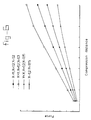
- Figure 6 shows a functional relationship between said force and the compression distance for some selected dimensions of X, Y, and R.
- the dimensions given are in millimetres.
- the relationship shown in figure 6 also depends on the material from which the spring contact member 22 is made.
- the force necessary to compress the spring contact member 22 is constant, and independent of the compression distance. However, in practice this is not possible.
- the dimensions of X, Y, and R are preferably chosen in such a way that the force necessary to compress the spring contact member 22 is between 0.2 and 0.4 Newton.
- Figure 7a shows a further embodiment of a connector block 3.
- Figure 7a shows a top view
- figure 7b shows a side view in the direction of arrow P1 in figure 7a
- figure 7c shows another side view in the direction of arrow P2 in figure 7a.
- Arrows P1 and P2 are perpendicular to each other.
- each of the contact terminals 10 is provided with a bent extremity 16 in order to establish a less sharp contact member 10 and to enhance the possible number of connecting and disconnecting operations between the connector block 3 and the mating cradle connector 2 (figure 2A).
- each of the bent extremities 16 is provided with a dimple 17 to further enhance the possible number of connecting and disconnecting operations.
- a rill 18 arranged in the axial direction of each contact terminal 10 in order to enforce the rigidity of each of the contact terminals 10.
- Figure 8a and 8b show two different possible orientations of the spring contact members 22.
- Both figures 8a and 8b show schematical top views of a connector block 3 having contact terminals arranged along one line L1.
- the spring contact members 22 have an angle of inclination relative to line L1 smaller than ⁇ /2, whereas in the embodiment shown in figure 8b the angle of inclination between the spring contact members 22 and line L1 is substantially ⁇ /2.
- the advantage of the embodiment according to figure 8a is that the width W1 of the connector block 3 may be smaller than the width W2 of the connector block 3 in the embodiment according to figure 8b.
- FIG 9 schematically shows a connector block 3 which is provided with a ground conductor 19.
- the ground conductor 19 is, during operation, connected to ground, e.g. through a contact pin connected to a ground layer on a printed circuit board to which the connector block 3 is connected.
- the purpose of the ground conductor 19 is to provide a static discharge capability for selected contact members 22, e.g. those contact members 22 which are connected to (C)MOS circuit parts on a printed circuit board.
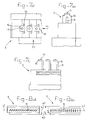
- Figure 10a shows a cross section through the connector block 3 according to figure 9 along line X-X
- figure 11a shows a cross section through the connector block 3 according to figure 9 along line XI-XI
- Figure 10b shows an enlarged view of the ground conductor 19 from the cross section of figure 10a
- figure 11b shows an enlarged view of the ground conductor 19 from the cross section of figure 11a.
- FIGs 10a and 10b show that each of the contact members 22 may be provided with an extension 21 at the extremity part of the corrugated spring part 13 adjacent to the ground conductor 19.
- the extension 21 is forced to the extremity of the cavity within the insulating housing 11 of the connector block by the spring action of the corrugated spring part 13.
- the extension 21 shown in figures 10a and 10b is insulated from the ground conductor 19 by a wall part of the insulating housing 11. Consequently, there is no electrical contact between the extension 21 and the ground conductor 19 and no static discharge capability is provided for.
- the extension 21 of the contact member 22 shown in figures 11a and 11b electrically contacts the ground conductor 19 when the connector block 3 is not connected to a cradle connector 2 and the extension 21 is forced to the extremity of the cavity within the housing 11.
- No insulating wall is present between the ground conductor 19 and the extension 21 in figures 11a and 11b. Therefore, any static charge on the contact member 22 in figures 11a and 11b will be conducted to ground through the ground conductor 19 when the connector block 3 is disconnected.
- Static charges on the contact member 22 of figures 11a and 11b are not able to damage (C)MOS circuit parts on a printed circuit board connected to contact pin 9.
- the ground conductor 19 in the embodiment shown in figures 9, 10a, 10b, 11a, and 11b is made of a small rod from any suitable metal, e.g. phosphor bronze.
- a ground conductor strip 19' instead of a rod 19: figures 12a, 12b and 12c.
- the ground conductor strip 19' may be applied to the inside wall of the insulating housing 11 of the connector block 3 by means of a method for selectively metallization of plastic connectors as described and claimed in European patent application 94202140.3.
- the ground conductor strip 19' is connected to ground, e.g. on a printed circuit board to which the connector block 3 is fixed, by suitable conductor means (not shown).
- Figure 12b shows a cross section through a cavity 24 in which the ground conductor strip 19' is exposed to electrically contact part 21 of spring part 13 when the connector block 3 is in its disconnected state.
- Figure 12c shows a cross section through a cavity 24 in which the ground conductor strip 19' is covered by an insulating layer 25 to prevent electrical contact between the strip 19' and the part 21 of the spring part 13 in this cavity 24.
- Figures 12a and 12b the latter showing an enlarged view of a construction detail of figure 12a, also show by-pass strips 20 provided on the inside wall of the cavity in which the contact member 22 is accommodated.
- the ground conductor strip 19' and the by-pass strip 20 are separate from each other and do not contact each other directly.
- the purpose of the by-pass strip 20 is to electrically contact as many U-shaped bases of the spring contact member 22 as possible and therefore to provide a short circuit for any electrical current through the contact member 22.
- the application of by-pass strip 20 reduces the electrical resistance between the contact terminal 10 and the contact pin 9 from each of the spring contact members 22.
- a by-pass strip 20 may be provided at both sides of each of the contact members 22, as shown in figure 12a.
- one by-pass strip 20 may be provided instead.
- the by-pass strips 20 may be applied on the inside walls of the cavity by the method for selective metallization of plastic connectors described in European patent application 94202140.3, referred to above.
- any other method for selective metallization may be used.
- a metal sleeve may be used, surrounding the spring contact member 22.
- the corrugated structure of the spring part 13 is, preferably, designed in such a way that the extension 21 is resiliently forced against the by-pass strip 20. Then, as little current as possible is flowing through the spring part 13 itself.
- the surface part of extension 21 contacting the by-pass strip 20 is preferably rounded and free of any burr.
- the first part of the corrugated structure opposite to extension 21 may be resiliently forced against by-pass strip 20.
- a ground conductor 19 or a ground conductor strip 19' is also applicable to any other kind of spring contact member, e.g. the ballpen-type of spring members from the prior art described in the introduction.
- spring contact member e.g. the ballpen-type of spring members from the prior art described in the introduction.
- those spring contact members 22 which electrically contact either the ground conductor 19 or the ground conductor strip 19' in the disconnected state will have to be at least slightly compressed in the connected state in order to avoid an electrical connection between the ground conductor 19 or the ground conductor strip 19' and the extension 21 during operation.
- those spring contact members 22 which have such a static discharge capability may extend slightly more from the body of the connector block 3 with their contact terminals 10 than do the other spring contact members 22 which do not have such a static discharge capability.
- Figure 13a shows an enlarged view of a spring contact member 22, preferably stamped from a thin metal sheet.
- Figure 13a further shows two folding lines f1, f2.
- Figure 13b shows the contact member 22' after such a folding operation which clearly shows that the width of the spring contact member is reduced relative to the width of the spring contact member 22 according to figure 13a.
- Figure 13c shows a side view of the spring contact member 22' according to figure 13b.
- Figure 13c shows that the gain in width is at the cost of the space needed in a direction perpendicular to the width direction of figure 13b.
- the spring contact members 22' may be provided with a bent extremity 16 provided with a dimple 17. Moreover the contact terminal 10 of the spring contact member 22' may be provided with a rill 18 like the original spring contact member 22.
- Figure 14 shows several spring contact members 22' which are made in accordance with the method described above.
- the spring contact members 22' are shown in a top view in figure 14 in which they show a C-shape.
- the distance between the legs of the C-shaped spring contact member 22' may be varied, as required. Different distances are shown in figure 14.
- the angle of inclination between the C-shaped spring contact members 22' and the line L1 may be varied, as required.
- Figure 14 also shows an alternative way of bending (or folding) a spring contact member 22 in order to produce an U-shaped spring contact member 22'' (when seen from a top view as in figure 14).
- the distance between the legs of such U-shaped spring contact members 22'' may be varied, as required.
- the angle of inclination between these U-shaped contact members 22'' and the line L1 may vary in accordance with the requirements. As explained above, the larger this angle of inclination the smaller the width w1 of the connector block 3 may be.
- Figure 15 shows two C-shaped spring contact members 22' produced in accordance with the method described above referring to figures 13a, 13b, and 13c.
- the legs of two adjacent spring contact members 22' may be interlaced as shown in figure 15.
- insulating walls (not shown) between the two adjacent spring contact members 22' may be provided in order to prevent undesired electrical contact between both spring contact members 22'.
- Figure 16 shows a further embodiment of a spring contact member 122.
- the spring contact member 122 differs from the spring contact member 22 (e.g. figure 13A) in the ratio of the distance between adjacent legs of the corrugated spring part 13' to the width of the corrugated spring part 13' as compared to the ratio of the distance between adjacent legs of the corrugated spring part 13 to the width of the corrugated spring part 13.
- Figure 17a shows that the invention is not restricted to corrugated spring contact members 22 with U-shapes.
- Figure 17a shows a spring contact member 222 comprising a corrugated spring part 13'' of which adjacent legs are arranged in a V-shape.
- the base parts of these V-shapes may be bent about a predetermined angle in order to reduce the width of the spring contact members 222.
- the bent base part is denoted by the reference sign 23.
- each of the contact terminals 10 of the spring contact member 222 may be provided with a rill 18 and with a bent extremity 16, the latter in turn being provided with a dimple 17.
- Adjacent bent base parts 23 may be bent in opposite directions, as shown in figure 17b which shows a side view of the spring contact member 222 according to figure 17a.
- the present invention is not restricted to the embodiments shown in the figures and described above.
- the connector blocks provided with spring contact members according to the invention are not only applicable in hand-held telephone sets. They can be applied wherever a connector block is needed having contact members with a spring action in their axial direction. Since the spring contact members themselves are made from a single piece of metal they can be easily produced. Moreover, assembling a connector block with several spring contact members according to the invention is relatively easy since the total number of pieces is reduced.
- the contact pin 9 of the contact members can be substituted by contact lips or the like suitable for hold down applications.
- the contact pins 9 may be substituted by any type of contact terminal known to a person skilled in the art.
- they may extend from a side face of block 3 instead of from the face opposite to contact terminals 10.
Priority Applications (4)
| Application Number | Priority Date | Filing Date | Title |
|---|---|---|---|
| EP19950201380 EP0718918B1 (fr) | 1994-12-20 | 1995-05-24 | Connecteur avec contact à ressort et des moyens de court-circuitage |
| JP8519917A JPH10510947A (ja) | 1994-12-20 | 1995-12-20 | スプリングコンタクト部材及び短絡手段を有するコネクタ |
| PCT/US1995/016429 WO1996019853A1 (fr) | 1994-12-20 | 1995-12-20 | Connecteur a element de contact a ressort et dispositif de mise en court-circuit |
| KR10-1997-0704203A KR100414838B1 (ko) | 1994-12-20 | 1997-06-20 | 스프링접촉부재및단락수단을갖는커넥터 |
Applications Claiming Priority (3)
| Application Number | Priority Date | Filing Date | Title |
|---|---|---|---|
| EP94203702 | 1994-12-20 | ||
| EP94203702 | 1994-12-20 | ||
| EP19950201380 EP0718918B1 (fr) | 1994-12-20 | 1995-05-24 | Connecteur avec contact à ressort et des moyens de court-circuitage |
Publications (2)
| Publication Number | Publication Date |
|---|---|
| EP0718918A1 true EP0718918A1 (fr) | 1996-06-26 |
| EP0718918B1 EP0718918B1 (fr) | 1997-08-06 |
Family
ID=26136829
Family Applications (1)
| Application Number | Title | Priority Date | Filing Date |
|---|---|---|---|
| EP19950201380 Expired - Lifetime EP0718918B1 (fr) | 1994-12-20 | 1995-05-24 | Connecteur avec contact à ressort et des moyens de court-circuitage |
Country Status (4)
| Country | Link |
|---|---|
| EP (1) | EP0718918B1 (fr) |
| JP (1) | JPH10510947A (fr) |
| KR (1) | KR100414838B1 (fr) |
| WO (1) | WO1996019853A1 (fr) |
Cited By (9)
| Publication number | Priority date | Publication date | Assignee | Title |
|---|---|---|---|---|
| US5807123A (en) * | 1994-10-27 | 1998-09-15 | The Whitaker Corporation | Radio-telephone cradle connector |
| EP0898333A2 (fr) * | 1997-08-19 | 1999-02-24 | Berg Electronics Manufacturing B.V. | Verrouillage de connecteur |
| US5954529A (en) * | 1995-12-20 | 1999-09-21 | Berg Technology, Inc. | Connector with spring contact member and shorting means |
| US5967856A (en) * | 1995-12-20 | 1999-10-19 | Berg Technology, Inc. | Connector with spring contact member and shorting means |
| EP0969560A1 (fr) * | 1998-07-02 | 2000-01-05 | Framatome Connectors International | Contact facial pour connecteur d'accessoire pour téléphone mobile |
| US6071141A (en) * | 1998-05-14 | 2000-06-06 | Berg Technology, Inc. | Connector latches |
| DE19953017A1 (de) * | 1999-11-04 | 2001-05-10 | Erni Elektroapp | Elektrische Steckverbindung |
| US6626708B2 (en) | 2001-03-30 | 2003-09-30 | Tyco Electronics Corporation | Single piece spring contact |
| DE102012223443A1 (de) * | 2012-12-17 | 2014-06-18 | Tyco Electronics Amp Gmbh | Federkontakt für einen Steckverbinder und Steckverbinder mit einem solchen Federkontakt |
Families Citing this family (7)
| Publication number | Priority date | Publication date | Assignee | Title |
|---|---|---|---|---|
| JP3520468B2 (ja) * | 2000-06-21 | 2004-04-19 | 日本航空電子工業株式会社 | コネクタ |
| JP5401101B2 (ja) * | 2009-01-08 | 2014-01-29 | 富士通コンポーネント株式会社 | コンタクト部材、及び該コンタクト部材を含むコネクタ |
| JP5758756B2 (ja) * | 2011-09-12 | 2015-08-05 | タイコエレクトロニクスジャパン合同会社 | 電気コネクタ |
| JP5708430B2 (ja) | 2011-10-14 | 2015-04-30 | オムロン株式会社 | 接触子 |
| JP6026130B2 (ja) * | 2012-04-10 | 2016-11-16 | 富士通コンポーネント株式会社 | コンタクト、コネクタ |
| JP6744209B2 (ja) * | 2016-12-27 | 2020-08-19 | 株式会社エンプラス | 電気接触子及び電気部品用ソケット |
| CN114267975B (zh) * | 2021-12-07 | 2024-03-08 | 北京泰力控科技有限公司 | 一种压接型弹性连接器 |
Citations (9)
| Publication number | Priority date | Publication date | Assignee | Title |
|---|---|---|---|---|
| US3903385A (en) | 1973-10-25 | 1975-09-02 | E Advanced Packaging Inc Sa | Shorting bar switch in electrical connector biasing assembly |
| US4070557A (en) | 1976-07-26 | 1978-01-24 | Northern Telecom Limited | Apparatus for providing closed loop conditions in vacant module positions |
| US4161346A (en) * | 1978-08-22 | 1979-07-17 | Amp Incorporated | Connecting element for surface to surface connectors |
| EP0256541A2 (fr) * | 1986-08-19 | 1988-02-24 | Feinmetall Gesellschaft mit beschrÀ¤nkter Haftung | Dispositif d'établissement de contacts |
| US4734051A (en) * | 1987-02-02 | 1988-03-29 | G & H Technology, Inc. | Electrical connector butt contact |
| US4778404A (en) * | 1983-12-27 | 1988-10-18 | Amp Incorporated | Spring terminal |
| US4954087A (en) | 1988-04-27 | 1990-09-04 | I-Stat Corporation | Static-free interrogating connector for electric components |
| EP0573690A1 (fr) * | 1992-06-11 | 1993-12-15 | GEC Alsthom T&D AG | Contact à pression |
| DE4344272A1 (de) * | 1992-12-24 | 1994-06-30 | Whitaker Corp | Elektrische Kontaktelemente für Zwischengliedkonstruktionen |
Family Cites Families (9)
| Publication number | Priority date | Publication date | Assignee | Title |
|---|---|---|---|---|
| US4179178A (en) * | 1978-02-02 | 1979-12-18 | Rca Corporation | Plug-in circuit cartridge with electrostatic charge protection |
| US4199209A (en) * | 1978-08-18 | 1980-04-22 | Amp Incorporated | Electrical interconnecting device |
| US4384757A (en) * | 1980-12-18 | 1983-05-24 | Amp Incorporated | Terminal for connecting a ceramic chip to a printed circuit board |
| US4805885A (en) * | 1982-12-21 | 1989-02-21 | Amp Incorporated | Sinuous spring |
| US4647126A (en) * | 1985-06-17 | 1987-03-03 | Sperry Corporation | Compliant lead clip |
| CA1298371C (fr) * | 1988-02-01 | 1992-03-31 | John S. Burg | Contact electrique moule facilitant les connexions |
| JPH0658812B2 (ja) * | 1988-07-08 | 1994-08-03 | 日本電信電話株式会社 | 接続子 |
| JP2627942B2 (ja) * | 1988-10-27 | 1997-07-09 | 日本エー・エム・ピー株式会社 | エアバッグ用コネクタ |
| US5409387A (en) * | 1993-08-17 | 1995-04-25 | Berg Technology, Inc. | Connector with passive switch for electrostatic discharge |
-
1995
- 1995-05-24 EP EP19950201380 patent/EP0718918B1/fr not_active Expired - Lifetime
- 1995-12-20 JP JP8519917A patent/JPH10510947A/ja not_active Ceased
- 1995-12-20 WO PCT/US1995/016429 patent/WO1996019853A1/fr active IP Right Grant
-
1997
- 1997-06-20 KR KR10-1997-0704203A patent/KR100414838B1/ko not_active IP Right Cessation
Patent Citations (10)
| Publication number | Priority date | Publication date | Assignee | Title |
|---|---|---|---|---|
| US3903385A (en) | 1973-10-25 | 1975-09-02 | E Advanced Packaging Inc Sa | Shorting bar switch in electrical connector biasing assembly |
| US4070557A (en) | 1976-07-26 | 1978-01-24 | Northern Telecom Limited | Apparatus for providing closed loop conditions in vacant module positions |
| US4161346A (en) * | 1978-08-22 | 1979-07-17 | Amp Incorporated | Connecting element for surface to surface connectors |
| US4778404A (en) * | 1983-12-27 | 1988-10-18 | Amp Incorporated | Spring terminal |
| EP0256541A2 (fr) * | 1986-08-19 | 1988-02-24 | Feinmetall Gesellschaft mit beschrÀ¤nkter Haftung | Dispositif d'établissement de contacts |
| US4773877A (en) | 1986-08-19 | 1988-09-27 | Feinmetall Gmbh | Contactor for an electronic tester |
| US4734051A (en) * | 1987-02-02 | 1988-03-29 | G & H Technology, Inc. | Electrical connector butt contact |
| US4954087A (en) | 1988-04-27 | 1990-09-04 | I-Stat Corporation | Static-free interrogating connector for electric components |
| EP0573690A1 (fr) * | 1992-06-11 | 1993-12-15 | GEC Alsthom T&D AG | Contact à pression |
| DE4344272A1 (de) * | 1992-12-24 | 1994-06-30 | Whitaker Corp | Elektrische Kontaktelemente für Zwischengliedkonstruktionen |
Cited By (10)
| Publication number | Priority date | Publication date | Assignee | Title |
|---|---|---|---|---|
| US5807123A (en) * | 1994-10-27 | 1998-09-15 | The Whitaker Corporation | Radio-telephone cradle connector |
| US5954529A (en) * | 1995-12-20 | 1999-09-21 | Berg Technology, Inc. | Connector with spring contact member and shorting means |
| US5967856A (en) * | 1995-12-20 | 1999-10-19 | Berg Technology, Inc. | Connector with spring contact member and shorting means |
| EP0898333A2 (fr) * | 1997-08-19 | 1999-02-24 | Berg Electronics Manufacturing B.V. | Verrouillage de connecteur |
| EP0898333A3 (fr) * | 1997-08-19 | 1999-11-03 | Berg Electronics Manufacturing B.V. | Verrouillage de connecteur |
| US6071141A (en) * | 1998-05-14 | 2000-06-06 | Berg Technology, Inc. | Connector latches |
| EP0969560A1 (fr) * | 1998-07-02 | 2000-01-05 | Framatome Connectors International | Contact facial pour connecteur d'accessoire pour téléphone mobile |
| DE19953017A1 (de) * | 1999-11-04 | 2001-05-10 | Erni Elektroapp | Elektrische Steckverbindung |
| US6626708B2 (en) | 2001-03-30 | 2003-09-30 | Tyco Electronics Corporation | Single piece spring contact |
| DE102012223443A1 (de) * | 2012-12-17 | 2014-06-18 | Tyco Electronics Amp Gmbh | Federkontakt für einen Steckverbinder und Steckverbinder mit einem solchen Federkontakt |
Also Published As
| Publication number | Publication date |
|---|---|
| JPH10510947A (ja) | 1998-10-20 |
| KR100414838B1 (ko) | 2004-05-24 |
| EP0718918B1 (fr) | 1997-08-06 |
| KR987001148A (ko) | 1998-04-30 |
| WO1996019853A1 (fr) | 1996-06-27 |
Similar Documents
| Publication | Publication Date | Title |
|---|---|---|
| US5967856A (en) | Connector with spring contact member and shorting means | |
| EP0718918B1 (fr) | Connecteur avec contact à ressort et des moyens de court-circuitage | |
| US3845455A (en) | Tubular conductor-in-slot connecting device | |
| US3903385A (en) | Shorting bar switch in electrical connector biasing assembly | |
| US7094093B2 (en) | Connector | |
| EP0005861A1 (fr) | Prise de connexion pour carte à circuit imprimé | |
| US6039590A (en) | Electrical connector with relatively movable two-part housing | |
| KR970707666A (ko) | 무선 전화기 크래들 컨넥터(Radio-telephone cradle connector) | |
| WO1999021256A2 (fr) | Connexion a bornes universelle | |
| KR870001865B1 (ko) | 리브 케이지형 단자 | |
| EP0497554B1 (fr) | Elément de fixation | |
| US4296988A (en) | Connector with improved terminal support | |
| EP0795930A1 (fr) | Contact électrique recevant une broche avec une force de contact élevée | |
| EP1257014A1 (fr) | Interface entre un circuit imprimé et un connecteur entrées/sorties | |
| US4501464A (en) | Modular connector with improved housing and contact structure | |
| EP0720256A1 (fr) | Boîte de raccordement électrique et borne de liaison utilisée avec une telle boîte | |
| US4445742A (en) | Electrical cable connector | |
| US5954529A (en) | Connector with spring contact member and shorting means | |
| EP0109297B1 (fr) | Eléments de contacts électriques et d'assemblages de connecteurs électriques | |
| EP0718919A1 (fr) | Connecteur avec contact à ressort et des moyens de court-circuitage | |
| KR0122784Y1 (ko) | 전기 커넥터가 부착된 소형 전기 모터 | |
| US6394829B1 (en) | Self-aligning electrical interconnect | |
| JP2908707B2 (ja) | 予負荷をもつ接触子を有する電気的コネクタ | |
| US6224388B1 (en) | In-board connector | |
| US5975934A (en) | Two-piece electrical connector of ZIF type using flexible printed circuit boards as contact elements |
Legal Events
| Date | Code | Title | Description |
|---|---|---|---|
| PUAI | Public reference made under article 153(3) epc to a published international application that has entered the european phase |
Free format text: ORIGINAL CODE: 0009012 |
|
| AK | Designated contracting states |
Kind code of ref document: A1 Designated state(s): CH DE FR GB IE LI NL SE |
|
| 17P | Request for examination filed |
Effective date: 19960617 |
|
| RBV | Designated contracting states (corrected) |
Designated state(s): CH DE FR GB IE LI NL SE |
|
| GRAG | Despatch of communication of intention to grant |
Free format text: ORIGINAL CODE: EPIDOS AGRA |
|
| 17Q | First examination report despatched |
Effective date: 19961115 |
|
| GRAH | Despatch of communication of intention to grant a patent |
Free format text: ORIGINAL CODE: EPIDOS IGRA |
|
| GRAH | Despatch of communication of intention to grant a patent |
Free format text: ORIGINAL CODE: EPIDOS IGRA |
|
| RAP1 | Party data changed (applicant data changed or rights of an application transferred) |
Owner name: BERG ELECTRONICS MANUFACTURING B.V. Owner name: CONNECTOR SYSTEMS TECHNOLOGY N.V. |
|
| GRAA | (expected) grant |
Free format text: ORIGINAL CODE: 0009210 |
|
| AK | Designated contracting states |
Kind code of ref document: B1 Designated state(s): CH DE FR GB IE LI NL SE |
|
| REG | Reference to a national code |
Ref country code: CH Ref legal event code: NV Representative=s name: PATENTANWALTSBUREAU R. A. MASPOLI Ref country code: CH Ref legal event code: EP |
|
| REF | Corresponds to: |
Ref document number: 69500525 Country of ref document: DE Date of ref document: 19970911 |
|
| ET | Fr: translation filed | ||
| PLBE | No opposition filed within time limit |
Free format text: ORIGINAL CODE: 0009261 |
|
| STAA | Information on the status of an ep patent application or granted ep patent |
Free format text: STATUS: NO OPPOSITION FILED WITHIN TIME LIMIT |
|
| 26N | No opposition filed | ||
| REG | Reference to a national code |
Ref country code: GB Ref legal event code: IF02 |
|
| PGFP | Annual fee paid to national office [announced via postgrant information from national office to epo] |
Ref country code: GB Payment date: 20050406 Year of fee payment: 11 |
|
| PGFP | Annual fee paid to national office [announced via postgrant information from national office to epo] |
Ref country code: NL Payment date: 20050407 Year of fee payment: 11 |
|
| PGFP | Annual fee paid to national office [announced via postgrant information from national office to epo] |
Ref country code: IE Payment date: 20050414 Year of fee payment: 11 |
|
| PGFP | Annual fee paid to national office [announced via postgrant information from national office to epo] |
Ref country code: SE Payment date: 20050503 Year of fee payment: 11 |
|
| PGFP | Annual fee paid to national office [announced via postgrant information from national office to epo] |
Ref country code: FR Payment date: 20050517 Year of fee payment: 11 |
|
| PGFP | Annual fee paid to national office [announced via postgrant information from national office to epo] |
Ref country code: CH Payment date: 20050613 Year of fee payment: 11 |
|
| PG25 | Lapsed in a contracting state [announced via postgrant information from national office to epo] |
Ref country code: IE Free format text: LAPSE BECAUSE OF NON-PAYMENT OF DUE FEES Effective date: 20060524 Ref country code: GB Free format text: LAPSE BECAUSE OF NON-PAYMENT OF DUE FEES Effective date: 20060524 |
|
| PG25 | Lapsed in a contracting state [announced via postgrant information from national office to epo] |
Ref country code: SE Free format text: LAPSE BECAUSE OF NON-PAYMENT OF DUE FEES Effective date: 20060525 |
|
| PG25 | Lapsed in a contracting state [announced via postgrant information from national office to epo] |
Ref country code: LI Free format text: LAPSE BECAUSE OF NON-PAYMENT OF DUE FEES Effective date: 20060531 Ref country code: CH Free format text: LAPSE BECAUSE OF NON-PAYMENT OF DUE FEES Effective date: 20060531 |
|
| PG25 | Lapsed in a contracting state [announced via postgrant information from national office to epo] |
Ref country code: NL Free format text: LAPSE BECAUSE OF NON-PAYMENT OF DUE FEES Effective date: 20061201 |
|
| REG | Reference to a national code |
Ref country code: CH Ref legal event code: PL |
|
| EUG | Se: european patent has lapsed | ||
| GBPC | Gb: european patent ceased through non-payment of renewal fee |
Effective date: 20060524 |
|
| NLV4 | Nl: lapsed or anulled due to non-payment of the annual fee |
Effective date: 20061201 |
|
| REG | Reference to a national code |
Ref country code: IE Ref legal event code: MM4A |
|
| REG | Reference to a national code |
Ref country code: FR Ref legal event code: ST Effective date: 20070131 |
|
| PGFP | Annual fee paid to national office [announced via postgrant information from national office to epo] |
Ref country code: DE Payment date: 20070531 Year of fee payment: 13 |
|
| PG25 | Lapsed in a contracting state [announced via postgrant information from national office to epo] |
Ref country code: FR Free format text: LAPSE BECAUSE OF NON-PAYMENT OF DUE FEES Effective date: 20060531 |
|
| PG25 | Lapsed in a contracting state [announced via postgrant information from national office to epo] |
Ref country code: DE Free format text: LAPSE BECAUSE OF NON-PAYMENT OF DUE FEES Effective date: 20081202 |