EP0718073B1 - System and method for sleeving a heat transfer tube belonging to a nuclear heat exchanger - Google Patents
System and method for sleeving a heat transfer tube belonging to a nuclear heat exchanger Download PDFInfo
- Publication number
- EP0718073B1 EP0718073B1 EP95309308A EP95309308A EP0718073B1 EP 0718073 B1 EP0718073 B1 EP 0718073B1 EP 95309308 A EP95309308 A EP 95309308A EP 95309308 A EP95309308 A EP 95309308A EP 0718073 B1 EP0718073 B1 EP 0718073B1
- Authority
- EP
- European Patent Office
- Prior art keywords
- sleeve
- tube
- bladder
- support body
- outside diameter
- Prior art date
- Legal status (The legal status is an assumption and is not a legal conclusion. Google has not performed a legal analysis and makes no representation as to the accuracy of the status listed.)
- Expired - Lifetime
Links
Images



Classifications
-
- F—MECHANICAL ENGINEERING; LIGHTING; HEATING; WEAPONS; BLASTING
- F28—HEAT EXCHANGE IN GENERAL
- F28F—DETAILS OF HEAT-EXCHANGE AND HEAT-TRANSFER APPARATUS, OF GENERAL APPLICATION
- F28F11/00—Arrangements for sealing leaky tubes and conduits
- F28F11/02—Arrangements for sealing leaky tubes and conduits using obturating elements, e.g. washers, inserted and operated independently of each other
-
- B—PERFORMING OPERATIONS; TRANSPORTING
- B21—MECHANICAL METAL-WORKING WITHOUT ESSENTIALLY REMOVING MATERIAL; PUNCHING METAL
- B21D—WORKING OR PROCESSING OF SHEET METAL OR METAL TUBES, RODS OR PROFILES WITHOUT ESSENTIALLY REMOVING MATERIAL; PUNCHING METAL
- B21D39/00—Application of procedures in order to connect objects or parts, e.g. coating with sheet metal otherwise than by plating; Tube expanders
- B21D39/04—Application of procedures in order to connect objects or parts, e.g. coating with sheet metal otherwise than by plating; Tube expanders of tubes with tubes; of tubes with rods
-
- B—PERFORMING OPERATIONS; TRANSPORTING
- B21—MECHANICAL METAL-WORKING WITHOUT ESSENTIALLY REMOVING MATERIAL; PUNCHING METAL
- B21D—WORKING OR PROCESSING OF SHEET METAL OR METAL TUBES, RODS OR PROFILES WITHOUT ESSENTIALLY REMOVING MATERIAL; PUNCHING METAL
- B21D39/00—Application of procedures in order to connect objects or parts, e.g. coating with sheet metal otherwise than by plating; Tube expanders
- B21D39/08—Tube expanders
- B21D39/20—Tube expanders with mandrels, e.g. expandable
- B21D39/203—Tube expanders with mandrels, e.g. expandable expandable by fluid or elastic material
-
- B—PERFORMING OPERATIONS; TRANSPORTING
- B23—MACHINE TOOLS; METAL-WORKING NOT OTHERWISE PROVIDED FOR
- B23P—METAL-WORKING NOT OTHERWISE PROVIDED FOR; COMBINED OPERATIONS; UNIVERSAL MACHINE TOOLS
- B23P19/00—Machines for simply fitting together or separating metal parts or objects, or metal and non-metal parts, whether or not involving some deformation; Tools or devices therefor so far as not provided for in other classes
- B23P19/02—Machines for simply fitting together or separating metal parts or objects, or metal and non-metal parts, whether or not involving some deformation; Tools or devices therefor so far as not provided for in other classes for connecting objects by press fit or for detaching same
- B23P19/022—Extracting or inserting relatively long parts
-
- F—MECHANICAL ENGINEERING; LIGHTING; HEATING; WEAPONS; BLASTING
- F16—ENGINEERING ELEMENTS AND UNITS; GENERAL MEASURES FOR PRODUCING AND MAINTAINING EFFECTIVE FUNCTIONING OF MACHINES OR INSTALLATIONS; THERMAL INSULATION IN GENERAL
- F16L—PIPES; JOINTS OR FITTINGS FOR PIPES; SUPPORTS FOR PIPES, CABLES OR PROTECTIVE TUBING; MEANS FOR THERMAL INSULATION IN GENERAL
- F16L55/00—Devices or appurtenances for use in, or in connection with, pipes or pipe systems
-
- F—MECHANICAL ENGINEERING; LIGHTING; HEATING; WEAPONS; BLASTING
- F16—ENGINEERING ELEMENTS AND UNITS; GENERAL MEASURES FOR PRODUCING AND MAINTAINING EFFECTIVE FUNCTIONING OF MACHINES OR INSTALLATIONS; THERMAL INSULATION IN GENERAL
- F16L—PIPES; JOINTS OR FITTINGS FOR PIPES; SUPPORTS FOR PIPES, CABLES OR PROTECTIVE TUBING; MEANS FOR THERMAL INSULATION IN GENERAL
- F16L55/00—Devices or appurtenances for use in, or in connection with, pipes or pipe systems
- F16L55/16—Devices for covering leaks in pipes or hoses, e.g. hose-menders
- F16L55/162—Devices for covering leaks in pipes or hoses, e.g. hose-menders from inside the pipe
- F16L55/163—Devices for covering leaks in pipes or hoses, e.g. hose-menders from inside the pipe a ring, a band or a sleeve being pressed against the inner surface of the pipe
Definitions
- This invention generally relates to sleeving of tubular members and more particularly relates to a system and method for sleeving a heat transfer tube belonging to a nuclear heat exchanger, the tube having an obstruction therein in the form of a previously installed sleeve.
- nuclear heat exchanger or steam generator tubes may degrade and thus may not remain leaktight. Such degradation may occur, for example, at the elevation of the tubesheet or at the higher elevations of tube support plates. In any event, if through-wall cracking occurs due to the degradation, the radioactive primary fluid may leak through the crack and commingle with the nonradioactive secondary fluid, a highly undesirable result.
- the tube although degraded, may remain in service by sleeving the degraded portion of the tube.
- a tubular repair sleeve is inserted into the tube to cover the degraded portion of the tube.
- the sleeve is then secured to the tube by radially expanding the sleeve into intimate engagement with the inner wall of the tube, such that the degraded portion of the tube is spanned or covered.
- the sleeve is then welded or hard-rolled to complete the tube-to-sleeve seal. In this manner, the radioactive primary fluid is prevented from commingling with the non-radioactive secondary fluid even though the wall of the tube is degraded.
- Prior art sleeves are inserted into the tube and expanded typically by means of a hydraulic expansion mandrel.
- such prior art sleeves are relatively long in length (e.g., 305 cm (12 inches) or longer) and experience an amount of elastic "spring-back" away from the inside wall of the tube after the hydraulic expansion process is completed such that the pressure boundary of the steam generator tube is compromised although the tube has been "sleeved".
- prior art sleeves are expanded so that the outside diameter of the tube is enlarged or bulged at selected locations in the wall of the tube as the sleeve is expanded in order that the sleeve is suitably affixed to the tube.
- the heat transfer tube may further degrade at an elevation higher than the elevation where such a prior art sleeve has been previously installed. That is, the heat transfer tube may degrade at the elevation of any one of the tube support plates, which are at an elevation higher than the tubesheet.
- the previously installed first prior art sleeve whether it be located at the elevation of the tubesheet or the support plate, will present an obstacle to the free passage of a second prior art sleeve due to the smallest inside diameter of the installed first sleeve being smaller that the outside diameter of the second sleeve.
- a tube requiring sleeving at an elevation higher than the elevation of the previously installed tubesheet or support plate sleeve cannot be readily sleeved due to the obstruction created by the initially installed sleeve.
- the tube is typically plugged by means of a suitable tube plug, thereby removing the tube from service. Removing the heat transfer tube from service decreases the thermal efficiency of the steam generator, thereby lessening the economic desirability of operating the steam generator. Therefore, another problem in the art is to suitably sleeve a steam generator tube at an elevation higher than the elevation of a previously installed prior art sleeve.
- this patent does not disclose a suitable system and method for sleeving a heat transfer tube without enlarging the outside diameter of the tube and also does not disclose a system and method to suitably sleeve a steam generator tube at an elevation higher than the elevation of a previously installed prior art sleeve.
- Prior art document EP-A-0626232 discloses another method of sleeving a heat transfer tube belonging to a nuclear heat exchanger, but the method does not enable the tube to be sleeved without enlarging the outside diameter of the tube.
- the invention consists in a method of sleeving a heat transfer tube belonging to a nuclear heat exchanger, the tube having an outside diameter and a first sleeve disposed therein, the first sleeve having an inside diameter, the method comprising the steps of:
- An object of the present invention is to provide a system and method of sleeving a heat transfer tube belonging to a nuclear heat exchanger, the tube having a previously installed first sleeve therein obstructing the passage of a second sleeve to an elevation in the tube higher than the first sleeve.
- a feature of the present invention is the provision of a second sleeve having a predetermined length and an outside diameter smaller than the inside diameter of the installed first sleeve for admitting the second sleeve past the installed first sleeve.
- Another feature of the present invention is the provision of a support body having a resilient bladder theresurrounding for expanding the second sleeve along its entire length (i.e., full length) and for creating greater engagement with the tube inside diametral surface.
- Another feature of the present invention is the provision of a pressurizer for pressurizing the bladder, so that the sleeve expands along its entire length and into intimate engagement with the tube to sleeve the tube without enlarging the outside diameter of the tube.
- An advantage of the present invention is that the sleeve will not experience elastic "spring-back" away from the inside wall of the tube as the sleeve is expanded along its entire length, so that the pressure boundary of the steam generator tube is not compromised.
- Another advantage of the present invention is that the steam generator tube may now be sleeved at an elevation higher than the elevation of a previously installed prior art sleeve.
- Yet another advantage of the present invention is that not only can the sleeve of the present invention be installed at an elevation higher than the prior art sleeve, but also the sleeve can be installed above a previously installed sleeve belonging to the invention.
- FIG. 1 there is shown typical nuclear steam generator or heat exchanger, generally referred to as 10, for generating steam.
- Steam generator 10 comprises a shell 20 having a hemispherically-shaped lower portion 30.
- Disposed in shell 20 are a plurality of vertical inverted U-shaped heat transfer tubes 40 that extend through respective ones of a plurality of holes 50 (see Fig. 3) formed through each of a plurality of tube support plates 70.
- Each tube 40 has an inside surface 80 (see Fig. 3).
- a horizontal tubesheet 90 disposed in lower portion 30 below support plates 70 is a horizontal tubesheet 90 having holes 100 therethrough for receiving the end portions of respective ones of tubes 40.
- first inlet nozzle 110 and a first outlet nozzle 120 in fluid communication with an inlet plenum chamber 130 and with an outlet plenum chamber 140, respectively.
- First inlet nozzle 110 allows entry of a radioactive primary fluid into inlet plenum chamber 130, which primary fluid flows from inlet plenum chamber 130, through tubes 40 and into outlet plenum chamber 140, whereupon the primary fluid exits steam generator through outlet nozzle 120.
- a plurality of manway holes are formed through shell 20 below tubesheet 90 for allowing access to inlet plenum chamber 130 and outlet plenum chamber 140.
- a second inlet nozzle 160 for entry of a nonradioactive secondary fluid into shell 20.
- a second outlet nozzle 170 is attached to the top of shell 20 for exit of steam from steam generator 10.
- System 180 in operative condition to sleeve a selected one of tubes 40.
- a tube 40 may have a previously installed prior art first sleeve 190 secured therein by expanded portions 200, first sleeve 190 having a bore 210 therethrough and an hydraulically expanded expansion "transition zone" 215.
- System 180 comprises an elongate mandrel or support body 220, which is insertable into tube 40 and sized to pass through bore 210.
- Support body 220 includes an elongate main body portion 230 having an exterior surface thereon and having an externally threaded proximal end portion 240 and an externally threaded distal end portion 250.
- proximal end portion means that end portion nearer manway holes 150
- distal end portion means that end portion further away from manway holes 150.
- surrounding main body 230 is a resilient bladder 260 for reasons disclosed hereinbelow.
- a first end cap 270 Threadably connected to distal end portion 250 of main body 230 is a first end cap 270 having an annular cup-shaped first flange 280 for securing, such as by a press-fit, the distal end portion of bladder 260 between the distal end portion 240 of main body 230 and flange 280 of first end cap 270.
- a second end cap 290 threadably connected to proximal end portion 240 of main body 230 is a second end cap 290 having an annular cup-shaped second flange 300 for securing, such as by a press-fit, the proximal end portion of bladder 260 between proximal end portion 240 of main body 230 and flange 300 of second end cap 290.
- Second end cap 290 has an extended portion 310 thereof for intimately engaging an inner wall 320 of a flexible conduit 330. Extending through extended portion 310, through second end cap 290 and through main body 230 is a fluid flow channel 340 for reasons disclosed hereinbelow.
- Flow channel 340 terminates in a port 350 on the exterior surface of main body 230, port 350 being covered by bladder 260 as bladder 260 surrounds main body 230.
- surrounding bladder 260 is an elongate sleeve 360 having a predetermined length.
- Sleeve 360 also has a predetermined outside diameter less than the smallest diameter of the prior art sleeve 190 for passing through bore 210 of prior art sleeve 190 on its way to sleeve tube 40 at an elevation therein higher than the elevation of prior art sleeve 190.
- sleeve 360 is capable of being expanded over its entire length.
- sleeve 360 be expandable over its entire length. This is important because such "full-length" sleeve expansion provides a tube-to-sleeve contact area that is relatively large compared to prior art sleeves. A large tube-to-sleeve contact area reduces the maximum required pressure to hold the sleeve in place in tube 40. Since the maximum pressure can be reduced, the outside diameter of tube 40 need not be radially enlarged after sleeve 360 is expanded into engagement with tube 40 in order to affix sleeve 360 to tube 40.
- Avoiding enlargement of the outside diameter of tube 40 is desirable because enlargement of the outside diameter of tube 40 causes unwanted stress in the transition zone of the expansion region, which unwanted stress would otherwise lead to stress corrosion cracking.
- support body 220 be elongate. This is important because such a full-length or elongate support body 220 allows expansion of sleeve 360 without producing the tapered transition zones 215 such as is experienced at the end portions of prior art sleeves 190. The removal of the tapered transition zones allows a newly installed sleeve 360 to be located at any location in tube 40 due to this capability, regardless of the number of sleeves previously installed.
- conduit 330 is connected to a pressurizer 370 for supplying a pressurized fluid (e.g., air, water, oil, or the like) through conduit 330 and to channel 340 for radially expanding bladder 260.
- Pressurizer 370 may include a piston arrangement 372 connected to a drive motor 374 for driving piston arrangement 372, so that the fluid is suitably pressurized and depressurized as needed.
- a fluid reservoir 380 is in fluid communication with pressurizer for supplying fluid to and for withdrawing fluid from pressurizer 370.
- a controller is connected to motor 374, which is in turn connected to piston arrangement 372 of pressurizer 370, for controllably operating piston arrangement 372 and thus for controlling pressurizer 370.
- Controlling pressurizer 370 controllably pressurizes and depressurizes the fluid in conduit 330 in order to controllably pressurize and depressurize bladder 260.
- a translation mechanism such as a conduit driver 400, which may be connected to manway hole 150, engages conduit 330 for translating conduit 330, support body 220 and sleeve 360 axially in tube 40 and through bore 210 of prior art sleeve 190.
- an alignment mechanism generally referred to as 410, may be disposed in lower portion 30 of steam generator 10 and engaged with support body 220 for coaxially aligning support body 220 with tube 40.
- alignment mechanism 410 may be a ROSA (Remotely Operated Service Arm) robotic device available from the Westinghouse Electric Corporation, located in Pittsburgh, Pennsylvania.
- ROSA Remote Operated Service Arm
- Fig. 5 there is shown a graph illustrating the change in pressure acting on sleeve 360 as a function of time as sleeve 360 is expanded into engagement with tube 40 substantially over the entire length of sleeve 360.
- the fluid is pressurized to expand bladder 260 to increase the pressure acting on sleeve 360 until sleeve 360 begins to expand elastically from point "A" (approximately 27579 KPa (4,000 psia)) to point "B" (approximately 44816KPa (6,500 psia)), which represents the yield point of the sleeve material.
- Past point “B” sleeve 360 will deform plastically and contact inside surface 80 of tube 40 at point “C”(approximately 62053 KPa (9,000 psia)).
- Past point “C” bladder 260 will continue to expand sleeve 360 until a predetermined pressure is reached at point "D” (approximately 113074 KPa (16,400 psia)).
- point "D" approximately 113074 KPa (16,400 psia)
- tube 40 is not allowed to radially expand.
- sleeve 360 is quickly expanded the desired amount in less than approximately 10 seconds.
- sleeve 360 is plastically deformed to a point where there is no elastic return which would otherwise allow sleeve 360 to "draw-back" away from tube 40 after expansion of sleeve 360.
- tube 40 may have a nominal inside diameter of 19.69 mm (0.775 inch.
- Prior art sleeve 190 which may have a length of approximately 305 mm (12 inches) or greater, may have an inside diameter, at its most constricted point, of approximately 16.79 mm (0.661 inch).
- the sleeve 360 of the invention which may have a length of 305 mm (12 inches) or less, may have an outside diameter of approximately 0.640 inch and an inside diameter of approximately 14.33 mm (0.564 inch) in its unexpanded state.
- Sleeve 360 may be an "INCONEL" metal alloy composed substantially of nickel, chromium, iron and a trace amount of cobalt. In its full-length expanded state, sleeve 360 may have an outside diameter of approximately 19.69 mm (0.775 inch) for matingly engaging the inside diameter 80 of tube 40.
- an advantage of the present invention is that expansion of sleeve 360 will not enlarge the outside diameter of tube 40 and will not lead to elastic "springback" of sleeve 360.
- Another advantage of the present invention is that sleeve 360 is sized to pass through bore 210 of previously installed prior art sleeve 190, or through the bore of a previously installed sleeve 360, so that sleeve 360 may be affixed to tube 40 at an elevation higher than the elevation of previously installed prior art sleeve 190 or sleeve 360.
- a suitable eddy current coil may be integrally attached to support body 220 for locating the site of tube 40 to be sleeved by sleeve 360.
Landscapes
- Engineering & Computer Science (AREA)
- Mechanical Engineering (AREA)
- General Engineering & Computer Science (AREA)
- Physics & Mathematics (AREA)
- Thermal Sciences (AREA)
- Heat-Exchange Devices With Radiators And Conduit Assemblies (AREA)
- Pipe Accessories (AREA)
- Application Of Or Painting With Fluid Materials (AREA)
Description
- This invention generally relates to sleeving of tubular members and more particularly relates to a system and method for sleeving a heat transfer tube belonging to a nuclear heat exchanger, the tube having an obstruction therein in the form of a previously installed sleeve.
- Occasionally, nuclear heat exchanger or steam generator tubes may degrade and thus may not remain leaktight. Such degradation may occur, for example, at the elevation of the tubesheet or at the higher elevations of tube support plates. In any event, if through-wall cracking occurs due to the degradation, the radioactive primary fluid may leak through the crack and commingle with the nonradioactive secondary fluid, a highly undesirable result.
- However, the tube, although degraded, may remain in service by sleeving the degraded portion of the tube. When sleeving is performed, a tubular repair sleeve is inserted into the tube to cover the degraded portion of the tube. The sleeve is then secured to the tube by radially expanding the sleeve into intimate engagement with the inner wall of the tube, such that the degraded portion of the tube is spanned or covered. The sleeve is then welded or hard-rolled to complete the tube-to-sleeve seal. In this manner, the radioactive primary fluid is prevented from commingling with the non-radioactive secondary fluid even though the wall of the tube is degraded.
- Prior art sleeves are inserted into the tube and expanded typically by means of a hydraulic expansion mandrel. However, such prior art sleeves are relatively long in length (e.g., 305 cm (12 inches) or longer) and experience an amount of elastic "spring-back" away from the inside wall of the tube after the hydraulic expansion process is completed such that the pressure boundary of the steam generator tube is compromised although the tube has been "sleeved". Moreover, prior art sleeves are expanded so that the outside diameter of the tube is enlarged or bulged at selected locations in the wall of the tube as the sleeve is expanded in order that the sleeve is suitably affixed to the tube. However, enlargement of the tube outside diameter may cause undesirable stress in the "transition zone" of the expanded region of the tube which may in turn lead to further stress corrosion cracking of the tube. Such stress corrosion cracking may also compromise the pressure boundary of the steam generator tube. Therefore, a problem in the art is to sleeve a steam generator tube without enlarging the outside diameter of the tube and to sleeve the tube in such a manner that elastic "spring-back" is not experienced by the sleeve.
- In addition, the heat transfer tube may further degrade at an elevation higher than the elevation where such a prior art sleeve has been previously installed. That is, the heat transfer tube may degrade at the elevation of any one of the tube support plates, which are at an elevation higher than the tubesheet. However, the previously installed first prior art sleeve, whether it be located at the elevation of the tubesheet or the support plate, will present an obstacle to the free passage of a second prior art sleeve due to the smallest inside diameter of the installed first sleeve being smaller that the outside diameter of the second sleeve. Thus, a tube requiring sleeving at an elevation higher than the elevation of the previously installed tubesheet or support plate sleeve cannot be readily sleeved due to the obstruction created by the initially installed sleeve. When this occurs, the tube is typically plugged by means of a suitable tube plug, thereby removing the tube from service. Removing the heat transfer tube from service decreases the thermal efficiency of the steam generator, thereby lessening the economic desirability of operating the steam generator. Therefore, another problem in the art is to suitably sleeve a steam generator tube at an elevation higher than the elevation of a previously installed prior art sleeve.
- Apparatus and methods for sleeving steam generator tubes by expanding sleeves into engagement with the interior wall of the steam generator tube are known. One such apparatus and method is disclosed in U.S. Patent 4,783,890 issued November 15, 1988 in the name of Jean-Paul Gaudin titled "Method of Repairing A Steam Generator Tube By Means of Lining". This patent discloses a liner that is introduced into a nuclear steam generator tube, the liner being affixed to the tube by mechanical deformation of an end part of the liner. The plastic deformation of the liner causes elastic expansion of the tube, which thereafter contracts to grip the end part of the liner. However, this patent does not disclose a suitable system and method for sleeving a heat transfer tube without enlarging the outside diameter of the tube and also does not disclose a system and method to suitably sleeve a steam generator tube at an elevation higher than the elevation of a previously installed prior art sleeve.
- Prior art document EP-A-0626232 discloses another method of sleeving a heat transfer tube belonging to a nuclear heat exchanger, but the method does not enable the tube to be sleeved without enlarging the outside diameter of the tube.
- Therefore, what is needed and what is addressed by the present invention, is a method for suitably sleeving a heat transfer tube belonging to a nuclear heat exchanger, the tube having an obstruction therein in the form of a previously installed sleeve.
- The invention consists in a method of sleeving a heat transfer tube belonging to a nuclear heat exchanger, the tube having an outside diameter and a first sleeve disposed therein, the first sleeve having an inside diameter, the method comprising the steps of:
- (a) inserting an elongate support body into the tube, the support body having a resilient bladder there-surrounding and a tubular second sleeve surrounding the bladder, the sleeve having a predetermined length and a predetermined outside diameter less than the inside diameter of the first sleeve for admitting the second sleeve past the first sleeve;
- (b) radially expanding the second sleeve by expanding the bladder; and
- (c) pressurizing the bladder to expand the bladder by
operating a pressurizer in communication with the bladder;
and characterized in that:
the second sleeve has a circumferential thickness when inserted into the tube with the bladder and then is plastically expanded beyond the inside diameter of the first sleeve and into intimate engagement with the tube over the entire length of the sleeve without enlarging the outside diameter of the tube. -
- An object of the present invention is to provide a system and method of sleeving a heat transfer tube belonging to a nuclear heat exchanger, the tube having a previously installed first sleeve therein obstructing the passage of a second sleeve to an elevation in the tube higher than the first sleeve.
- A feature of the present invention is the provision of a second sleeve having a predetermined length and an outside diameter smaller than the inside diameter of the installed first sleeve for admitting the second sleeve past the installed first sleeve.
- Another feature of the present invention is the provision of a support body having a resilient bladder theresurrounding for expanding the second sleeve along its entire length (i.e., full length) and for creating greater engagement with the tube inside diametral surface.
- Another feature of the present invention is the provision of a pressurizer for pressurizing the bladder, so that the sleeve expands along its entire length and into intimate engagement with the tube to sleeve the tube without enlarging the outside diameter of the tube.
- An advantage of the present invention is that the sleeve will not experience elastic "spring-back" away from the inside wall of the tube as the sleeve is expanded along its entire length, so that the pressure boundary of the steam generator tube is not compromised.
- Another advantage of the present invention is that the steam generator tube may now be sleeved at an elevation higher than the elevation of a previously installed prior art sleeve.
- Yet another advantage of the present invention is that not only can the sleeve of the present invention be installed at an elevation higher than the prior art sleeve, but also the sleeve can be installed above a previously installed sleeve belonging to the invention.
- These and other objects, features and advantages of the present invention will become apparent to those skilled in the art upon a reading of the following detailed description when taken in conjunction with the drawings wherein there is shown and described illustrative embodiments of the invention.
- While the specification concludes with claims particularly pointing out and distinctly claiming the subject matter of the invention, it is believed the invention will be better understood from the following description taken in conjunction with the accompanying drawings wherein:
- Figure 1 is a perspective view in partial vertical section of a typical nuclear steam generator with parts removed for clarity, the steam generator having a plurality of inverted U-shaped heat transfer tubes disposed therein;
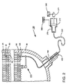
- Figure 2 is a view in elevation of part of the steam generator showing the use of the method of the invention in operation to sleeve a selected one of the tubes;
- Figure 3 is a view in elevation of a support body and a surrounding sleeve disposed in the tube;
- Figure 4 is a view in elevation of the selected tube
showing a previously installed prior art first sleeve
therein and a second sleeve provided according to the
invention intimately engaging the tube at an elevation
higher than the elevation of the prior art first sleeve;
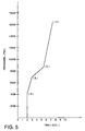
and - Figure 5 shows a graph illustrating the change in pressure acting on the sleeve as a function of time as the sleeve is expanded into engagement with the tube without expanding the tube.
-
- Referring to Fig. 1, there is shown typical nuclear steam generator or heat exchanger, generally referred to as 10, for generating steam.
Steam generator 10 comprises ashell 20 having a hemispherically-shapedlower portion 30. Disposed inshell 20 are a plurality of vertical inverted U-shapedheat transfer tubes 40 that extend through respective ones of a plurality of holes 50 (see Fig. 3) formed through each of a plurality oftube support plates 70. Eachtube 40 has an inside surface 80 (see Fig. 3). As shown in Fig. 1, disposed inlower portion 30 belowsupport plates 70 is ahorizontal tubesheet 90 havingholes 100 therethrough for receiving the end portions of respective ones oftubes 40. Attached toshell 20 are afirst inlet nozzle 110 and afirst outlet nozzle 120 in fluid communication with an inlet plenum chamber 130 and with an outlet plenum chamber 140, respectively.First inlet nozzle 110 allows entry of a radioactive primary fluid into inlet plenum chamber 130, which primary fluid flows from inlet plenum chamber 130, throughtubes 40 and into outlet plenum chamber 140, whereupon the primary fluid exits steam generator throughoutlet nozzle 120. A plurality of manway holes (only one of which is shown) are formed throughshell 20 belowtubesheet 90 for allowing access to inlet plenum chamber 130 and outlet plenum chamber 140. Moreover, attached toshell 20 abovetubesheet 90 is asecond inlet nozzle 160 for entry of a nonradioactive secondary fluid intoshell 20. Asecond outlet nozzle 170 is attached to the top ofshell 20 for exit of steam fromsteam generator 10. - Referring to Figs. 2, 3 and 4, there is shown the system of the invention, generally referred to as 180, in operative condition to sleeve a selected one of
tubes 40. As best seen in Fig. 4, such atube 40 may have a previously installed prior artfirst sleeve 190 secured therein by expandedportions 200,first sleeve 190 having abore 210 therethrough and an hydraulically expanded expansion "transition zone" 215.System 180 comprises an elongate mandrel orsupport body 220, which is insertable intotube 40 and sized to pass throughbore 210.Support body 220 includes an elongatemain body portion 230 having an exterior surface thereon and having an externally threadedproximal end portion 240 and an externally threadeddistal end portion 250. Of course, it will be understood with reference to the several figures that "proximal end portion" means that end portion nearer manway holes 150 and "distal end portion" means that end portion further away from manway holes 150. - Referring again to Figs. 2, 3 and 4, surrounding
main body 230 is aresilient bladder 260 for reasons disclosed hereinbelow. Threadably connected todistal end portion 250 ofmain body 230 is afirst end cap 270 having an annular cup-shapedfirst flange 280 for securing, such as by a press-fit, the distal end portion ofbladder 260 between thedistal end portion 240 ofmain body 230 andflange 280 offirst end cap 270. Moreover, threadably connected toproximal end portion 240 ofmain body 230 is asecond end cap 290 having an annular cup-shapedsecond flange 300 for securing, such as by a press-fit, the proximal end portion ofbladder 260 betweenproximal end portion 240 ofmain body 230 andflange 300 ofsecond end cap 290.Second end cap 290 has an extendedportion 310 thereof for intimately engaging aninner wall 320 of aflexible conduit 330. Extending throughextended portion 310, throughsecond end cap 290 and throughmain body 230 is afluid flow channel 340 for reasons disclosed hereinbelow.Flow channel 340 terminates in aport 350 on the exterior surface ofmain body 230,port 350 being covered bybladder 260 asbladder 260 surroundsmain body 230. - As best seen in Figs. 3 and 4, surrounding
bladder 260 is anelongate sleeve 360 having a predetermined length.Sleeve 360 also has a predetermined outside diameter less than the smallest diameter of theprior art sleeve 190 for passing throughbore 210 ofprior art sleeve 190 on its way tosleeve tube 40 at an elevation therein higher than the elevation ofprior art sleeve 190. As described more fully hereinbelow,sleeve 360 is capable of being expanded over its entire length. - Applicants have discovered that it is important that
sleeve 360 be expandable over its entire length. This is important because such "full-length" sleeve expansion provides a tube-to-sleeve contact area that is relatively large compared to prior art sleeves. A large tube-to-sleeve contact area reduces the maximum required pressure to hold the sleeve in place intube 40. Since the maximum pressure can be reduced, the outside diameter oftube 40 need not be radially enlarged aftersleeve 360 is expanded into engagement withtube 40 in order to affixsleeve 360 totube 40. Avoiding enlargement of the outside diameter oftube 40 is desirable because enlargement of the outside diameter oftube 40 causes unwanted stress in the transition zone of the expansion region, which unwanted stress would otherwise lead to stress corrosion cracking. Moreover, it is important thatsupport body 220 be elongate. This is important because such a full-length orelongate support body 220 allows expansion ofsleeve 360 without producing the taperedtransition zones 215 such as is experienced at the end portions ofprior art sleeves 190. The removal of the tapered transition zones allows a newly installedsleeve 360 to be located at any location intube 40 due to this capability, regardless of the number of sleeves previously installed. - Returning to Fig. 2,
conduit 330 is connected to apressurizer 370 for supplying a pressurized fluid (e.g., air, water, oil, or the like) throughconduit 330 and to channel 340 for radially expandingbladder 260.Pressurizer 370 may include apiston arrangement 372 connected to adrive motor 374 for drivingpiston arrangement 372, so that the fluid is suitably pressurized and depressurized as needed. Afluid reservoir 380 is in fluid communication with pressurizer for supplying fluid to and for withdrawing fluid frompressurizer 370. A controller is connected tomotor 374, which is in turn connected topiston arrangement 372 ofpressurizer 370, for controllably operatingpiston arrangement 372 and thus for controllingpressurizer 370. Controllingpressurizer 370 controllably pressurizes and depressurizes the fluid inconduit 330 in order to controllably pressurize and depressurizebladder 260. In addition, a translation mechanism, such as aconduit driver 400, which may be connected tomanway hole 150, engagesconduit 330 for translatingconduit 330,support body 220 andsleeve 360 axially intube 40 and throughbore 210 ofprior art sleeve 190. Moreover, an alignment mechanism, generally referred to as 410, may be disposed inlower portion 30 ofsteam generator 10 and engaged withsupport body 220 for coaxially aligningsupport body 220 withtube 40. In this regard,alignment mechanism 410 may be a ROSA (Remotely Operated Service Arm) robotic device available from the Westinghouse Electric Corporation, located in Pittsburgh, Pennsylvania. - Turning now to Fig. 5, there is shown a graph illustrating the change in pressure acting on
sleeve 360 as a function of time assleeve 360 is expanded into engagement withtube 40 substantially over the entire length ofsleeve 360. As shown in Fig. 5, the fluid is pressurized to expandbladder 260 to increase the pressure acting onsleeve 360 untilsleeve 360 begins to expand elastically from point "A" (approximately 27579 KPa (4,000 psia)) to point "B" (approximately 44816KPa (6,500 psia)), which represents the yield point of the sleeve material. Past point "B",sleeve 360 will deform plastically and contact insidesurface 80 oftube 40 at point "C"(approximately 62053 KPa (9,000 psia)). Past point "C",bladder 260 will continue to expandsleeve 360 until a predetermined pressure is reached at point "D" (approximately 113074 KPa (16,400 psia)). However,tube 40 is not allowed to radially expand. In this manner,sleeve 360 is quickly expanded the desired amount in less than approximately 10 seconds. Moreover, it will be appreciated from Fig. 5 thatsleeve 360 is plastically deformed to a point where there is no elastic return which would otherwise allowsleeve 360 to "draw-back" away fromtube 40 after expansion ofsleeve 360. - By way of example only and not by way of limitation,
tube 40 may have a nominal inside diameter of 19.69 mm (0.775 inch.Prior art sleeve 190, which may have a length of approximately 305 mm (12 inches) or greater, may have an inside diameter, at its most constricted point, of approximately 16.79 mm (0.661 inch). Thesleeve 360 of the invention, which may have a length of 305 mm (12 inches) or less, may have an outside diameter of approximately 0.640 inch and an inside diameter of approximately 14.33 mm (0.564 inch) in its unexpanded state.Sleeve 360 may be an "INCONEL" metal alloy composed substantially of nickel, chromium, iron and a trace amount of cobalt. In its full-length expanded state,sleeve 360 may have an outside diameter of approximately 19.69 mm (0.775 inch) for matingly engaging theinside diameter 80 oftube 40. - It will be appreciated from the description hereinabove, that an advantage of the present invention is that expansion of
sleeve 360 will not enlarge the outside diameter oftube 40 and will not lead to elastic "springback" ofsleeve 360. Another advantage of the present invention is thatsleeve 360 is sized to pass throughbore 210 of previously installedprior art sleeve 190, or through the bore of a previously installedsleeve 360, so thatsleeve 360 may be affixed totube 40 at an elevation higher than the elevation of previously installedprior art sleeve 190 orsleeve 360. - Although the invention is illustrated and described herein in its preferred embodiment, it is not intended that the invention as illustrated and described be limited to the details shown, because various modifications may be obtained within the scope of the claims. For example, a suitable eddy current coil may be integrally attached to support
body 220 for locating the site oftube 40 to be sleeved bysleeve 360.
Claims (5)
- A method of sleeving a heat transfer tube (40) belonging to a nuclear heat exchanger (10), the tube (40) having an outside diameter and a first sleeve (190) disposed therein, the first sleeve (190) having an inside diameter, the method comprising the steps of:(a) inserting an elongate support body (270) into the tube (40), the support body (270) having a resilient bladder (260) there-surrounding and a tubular second sleeve (360) surrounding the bladder (260), the sleeve (360) having a predetermined length and a predetermined outside diameter less than the inside diameter of the first sleeve (190) for admitting the second sleeve (360) past the first sleeve (190);(b) radially expanding the second sleeve (360) by expanding the bladder (260); and(c) pressurizing the bladder (360) to expand the bladder (260) by operating a pressurizer (370) in communication with the bladder (260);
and characterized in that:
the second sleeve (360) has a circumferential thickness when inserted into the tube (40) with the bladder and then is plastically expanded beyond the inside diameter of the first sleeve (190) and into intimate engagement with the tube (40) over the entire length of the sleeve without enlarging the outside diameter of the tube (40). - The method of Claim 1, wherein the second sleeve is plastically expanded at a hydraulic pressure of from 6,500 psi (44815 KPa) to 16,400 psi (113074 KPa).
- The method of Claim 2, wherein the second sleeve is plastically expanded at a hydraulic pressure of no more than 16,400 psi (113074 KPa).
- The method of claim 1, further comprising the step of coaxially aligning the support body (220) with the tube (40) by operating an alignment mechanism (410) connected to the support body (220).
- The method of claim 1, further comprising the step of translating the support body (220) axially in the tube (40) past the first sleeve (190) by operating a translation mechanism (400) connected to the support body (220).
Applications Claiming Priority (2)
| Application Number | Priority Date | Filing Date | Title |
|---|---|---|---|
| US36366394A | 1994-12-23 | 1994-12-23 | |
| US363663 | 1994-12-23 |
Publications (2)
| Publication Number | Publication Date |
|---|---|
| EP0718073A1 EP0718073A1 (en) | 1996-06-26 |
| EP0718073B1 true EP0718073B1 (en) | 2001-11-28 |
Family
ID=23431157
Family Applications (1)
| Application Number | Title | Priority Date | Filing Date |
|---|---|---|---|
| EP95309308A Expired - Lifetime EP0718073B1 (en) | 1994-12-23 | 1995-12-20 | System and method for sleeving a heat transfer tube belonging to a nuclear heat exchanger |
Country Status (4)
| Country | Link |
|---|---|
| EP (1) | EP0718073B1 (en) |
| KR (1) | KR100435136B1 (en) |
| CA (1) | CA2165928A1 (en) |
| ES (1) | ES2165899T3 (en) |
Families Citing this family (2)
| Publication number | Priority date | Publication date | Assignee | Title |
|---|---|---|---|---|
| CN108393652B (en) * | 2018-05-14 | 2024-02-20 | 辽宁工程技术大学 | Remanufacturing repair equipment for stainless steel covered upright column with horizontal structure |
| JP7249971B2 (en) * | 2020-05-22 | 2023-03-31 | 東芝三菱電機産業システム株式会社 | Manufacturing method and pressing device for heat exchanger for rotary electric machine |
Family Cites Families (9)
| Publication number | Priority date | Publication date | Assignee | Title |
|---|---|---|---|---|
| ES523894A0 (en) * | 1982-07-27 | 1984-06-16 | Foster Wheeler Energy Corp | EXPLOSIVELY ACTIVATED SET TO REPAIR A TUBE ON A TUBE SHEET. |
| US4616392A (en) * | 1984-10-04 | 1986-10-14 | Westinghouse Electric Corp. | Bladder mandrel for hydraulic expansions of tubes and sleeves |
| FR2579738B1 (en) | 1985-03-29 | 1987-06-26 | Framatome Sa | METHOD FOR REPAIRING A STEAM GENERATOR TUBE BY LINING |
| US4941512A (en) * | 1988-11-14 | 1990-07-17 | Cti Industries, Inc. | Method of repairing heat exchanger tube ends |
| DE4019599C1 (en) * | 1990-06-20 | 1992-01-16 | Abb Reaktor Gmbh, 6800 Mannheim, De | |
| FR2666408A1 (en) * | 1990-09-05 | 1992-03-06 | Framatome Sa | Device for expanding a tubular member |
| US5301424A (en) * | 1992-11-30 | 1994-04-12 | Westinghouse Electric Corp. | Method for hydraulically expanding tubular members |
| EP0626232A1 (en) * | 1993-05-26 | 1994-11-30 | Westinghouse Electric Corporation | Device and method for sleeving an inside surface of a tube |
| US5479699A (en) * | 1994-02-07 | 1996-01-02 | Westinghouse Electric Corporation | Apparatus for expanding tubular members |
-
1995
- 1995-12-20 ES ES95309308T patent/ES2165899T3/en not_active Expired - Lifetime
- 1995-12-20 EP EP95309308A patent/EP0718073B1/en not_active Expired - Lifetime
- 1995-12-21 CA CA002165928A patent/CA2165928A1/en not_active Abandoned
- 1995-12-22 KR KR1019950054931A patent/KR100435136B1/en not_active Expired - Lifetime
Also Published As
| Publication number | Publication date |
|---|---|
| ES2165899T3 (en) | 2002-04-01 |
| KR960021241A (en) | 1996-07-18 |
| KR100435136B1 (en) | 2004-07-31 |
| CA2165928A1 (en) | 1996-06-24 |
| EP0718073A1 (en) | 1996-06-26 |
Similar Documents
| Publication | Publication Date | Title |
|---|---|---|
| US5752311A (en) | Method for expanding tubular members | |
| US5791046A (en) | Method of sleeving damaged heat exchanger tubes | |
| US5667252A (en) | Internal sleeve with a plurality of lands and teeth | |
| EP2413083B1 (en) | Method of repairing a tubular member of an apparatus | |
| US4646816A (en) | Simplified tube plugging | |
| EP0120277A1 (en) | Compression sleeve for a tube repair | |
| EP0047407A1 (en) | Sleeving method | |
| US6247231B1 (en) | Method for repairing heat exchanger tubing through partial tube replacement | |
| EP0718073A1 (en) | System and method for sleeving a heat transfer tube belonging to a nuclear heat exchanger | |
| US5301424A (en) | Method for hydraulically expanding tubular members | |
| EP0626232A1 (en) | Device and method for sleeving an inside surface of a tube | |
| CA2144599C (en) | Flexible hydraulic expansion mandrel | |
| US5752317A (en) | Method of restricting transverse displacement of a nuclear heat exchanger tube support plate | |
| JPH07181285A (en) | Welding device and method for damaged pipe lower part of steam generator for nuclear reactor | |
| EP0635112A1 (en) | Apparatus for use in repairing a pipeline and method for carrying out such repairs | |
| SE434086B (en) | DEVICE FOR PLUGING A DRAWING IN A PRESSURE | |
| US5135705A (en) | Plug and method for plugging a penetration in a pressure vessel wall | |
| US5715598A (en) | Method for sealing a bare hole defined by a nuclear heat exchanger tubesheet | |
| US6189212B1 (en) | Method for tube plug removal | |
| EP0121137A1 (en) | Seal welded tube sleeve | |
| US6421916B1 (en) | Method for the removal of rib plugs using a spiral TIG welding technique to relax the rib plug | |
| US20020059725A1 (en) | Heat exchanger sleeve end expander | |
| WO2018106244A1 (en) | Method of cavitation peening an internal surface of a hollow part | |
| JPH0921897A (en) | How to replace the incore monitor housing | |
| US20110114213A1 (en) | water powered hydraulic swage system and method for well casing repair |
Legal Events
| Date | Code | Title | Description |
|---|---|---|---|
| PUAI | Public reference made under article 153(3) epc to a published international application that has entered the european phase |
Free format text: ORIGINAL CODE: 0009012 |
|
| AK | Designated contracting states |
Kind code of ref document: A1 Designated state(s): BE ES FR GB |
|
| 17P | Request for examination filed |
Effective date: 19961227 |
|
| 17Q | First examination report despatched |
Effective date: 19980506 |
|
| RAP1 | Party data changed (applicant data changed or rights of an application transferred) |
Owner name: WESTINGHOUSE ELECTRIC COMPANY LLC |
|
| GRAG | Despatch of communication of intention to grant |
Free format text: ORIGINAL CODE: EPIDOS AGRA |
|
| GRAG | Despatch of communication of intention to grant |
Free format text: ORIGINAL CODE: EPIDOS AGRA |
|
| GRAH | Despatch of communication of intention to grant a patent |
Free format text: ORIGINAL CODE: EPIDOS IGRA |
|
| GRAH | Despatch of communication of intention to grant a patent |
Free format text: ORIGINAL CODE: EPIDOS IGRA |
|
| GRAA | (expected) grant |
Free format text: ORIGINAL CODE: 0009210 |
|
| AK | Designated contracting states |
Kind code of ref document: B1 Designated state(s): BE ES FR GB |
|
| REG | Reference to a national code |
Ref country code: GB Ref legal event code: IF02 |
|
| ET | Fr: translation filed | ||
| REG | Reference to a national code |
Ref country code: ES Ref legal event code: FG2A Ref document number: 2165899 Country of ref document: ES Kind code of ref document: T3 |
|
| PLBE | No opposition filed within time limit |
Free format text: ORIGINAL CODE: 0009261 |
|
| STAA | Information on the status of an ep patent application or granted ep patent |
Free format text: STATUS: NO OPPOSITION FILED WITHIN TIME LIMIT |
|
| 26N | No opposition filed | ||
| PGFP | Annual fee paid to national office [announced via postgrant information from national office to epo] |
Ref country code: GB Payment date: 20141124 Year of fee payment: 20 Ref country code: ES Payment date: 20141215 Year of fee payment: 20 |
|
| PGFP | Annual fee paid to national office [announced via postgrant information from national office to epo] |
Ref country code: FR Payment date: 20141124 Year of fee payment: 20 |
|
| PGFP | Annual fee paid to national office [announced via postgrant information from national office to epo] |
Ref country code: BE Payment date: 20141205 Year of fee payment: 20 |
|
| REG | Reference to a national code |
Ref country code: GB Ref legal event code: PE20 Expiry date: 20151219 |
|
| PG25 | Lapsed in a contracting state [announced via postgrant information from national office to epo] |
Ref country code: GB Free format text: LAPSE BECAUSE OF EXPIRATION OF PROTECTION Effective date: 20151219 |
|
| REG | Reference to a national code |
Ref country code: ES Ref legal event code: FD2A Effective date: 20160329 |
|
| PG25 | Lapsed in a contracting state [announced via postgrant information from national office to epo] |
Ref country code: ES Free format text: LAPSE BECAUSE OF EXPIRATION OF PROTECTION Effective date: 20151221 |