EP0718038A2 - Apparatus for separating mixtures of microscopic small dielectric particles dispersed in a fluid or a gel - Google Patents
Apparatus for separating mixtures of microscopic small dielectric particles dispersed in a fluid or a gel Download PDFInfo
- Publication number
- EP0718038A2 EP0718038A2 EP96103459A EP96103459A EP0718038A2 EP 0718038 A2 EP0718038 A2 EP 0718038A2 EP 96103459 A EP96103459 A EP 96103459A EP 96103459 A EP96103459 A EP 96103459A EP 0718038 A2 EP0718038 A2 EP 0718038A2
- Authority
- EP
- European Patent Office
- Prior art keywords
- electrodes
- particles
- film
- particle
- electrode
- Prior art date
- Legal status (The legal status is an assumption and is not a legal conclusion. Google has not performed a legal analysis and makes no representation as to the accuracy of the status listed.)
- Granted
Links
Images


Classifications
-
- B—PERFORMING OPERATIONS; TRANSPORTING
- B03—SEPARATION OF SOLID MATERIALS USING LIQUIDS OR USING PNEUMATIC TABLES OR JIGS; MAGNETIC OR ELECTROSTATIC SEPARATION OF SOLID MATERIALS FROM SOLID MATERIALS OR FLUIDS; SEPARATION BY HIGH-VOLTAGE ELECTRIC FIELDS
- B03C—MAGNETIC OR ELECTROSTATIC SEPARATION OF SOLID MATERIALS FROM SOLID MATERIALS OR FLUIDS; SEPARATION BY HIGH-VOLTAGE ELECTRIC FIELDS
- B03C5/00—Separating dispersed particles from liquids by electrostatic effect
- B03C5/02—Separators
- B03C5/022—Non-uniform field separators
- B03C5/028—Non-uniform field separators using travelling electric fields, i.e. travelling wave dielectrophoresis [TWD]
-
- B—PERFORMING OPERATIONS; TRANSPORTING
- B01—PHYSICAL OR CHEMICAL PROCESSES OR APPARATUS IN GENERAL
- B01J—CHEMICAL OR PHYSICAL PROCESSES, e.g. CATALYSIS OR COLLOID CHEMISTRY; THEIR RELEVANT APPARATUS
- B01J19/00—Chemical, physical or physico-chemical processes in general; Their relevant apparatus
- B01J19/0093—Microreactors, e.g. miniaturised or microfabricated reactors
-
- B—PERFORMING OPERATIONS; TRANSPORTING
- B03—SEPARATION OF SOLID MATERIALS USING LIQUIDS OR USING PNEUMATIC TABLES OR JIGS; MAGNETIC OR ELECTROSTATIC SEPARATION OF SOLID MATERIALS FROM SOLID MATERIALS OR FLUIDS; SEPARATION BY HIGH-VOLTAGE ELECTRIC FIELDS
- B03C—MAGNETIC OR ELECTROSTATIC SEPARATION OF SOLID MATERIALS FROM SOLID MATERIALS OR FLUIDS; SEPARATION BY HIGH-VOLTAGE ELECTRIC FIELDS
- B03C5/00—Separating dispersed particles from liquids by electrostatic effect
- B03C5/005—Dielectrophoresis, i.e. dielectric particles migrating towards the region of highest field strength
-
- B—PERFORMING OPERATIONS; TRANSPORTING
- B03—SEPARATION OF SOLID MATERIALS USING LIQUIDS OR USING PNEUMATIC TABLES OR JIGS; MAGNETIC OR ELECTROSTATIC SEPARATION OF SOLID MATERIALS FROM SOLID MATERIALS OR FLUIDS; SEPARATION BY HIGH-VOLTAGE ELECTRIC FIELDS
- B03C—MAGNETIC OR ELECTROSTATIC SEPARATION OF SOLID MATERIALS FROM SOLID MATERIALS OR FLUIDS; SEPARATION BY HIGH-VOLTAGE ELECTRIC FIELDS
- B03C5/00—Separating dispersed particles from liquids by electrostatic effect
- B03C5/02—Separators
- B03C5/022—Non-uniform field separators
- B03C5/026—Non-uniform field separators using open-gradient differential dielectric separation, i.e. using electrodes of special shapes for non-uniform field creation, e.g. Fluid Integrated Circuit [FIC]
-
- G—PHYSICS
- G01—MEASURING; TESTING
- G01N—INVESTIGATING OR ANALYSING MATERIALS BY DETERMINING THEIR CHEMICAL OR PHYSICAL PROPERTIES
- G01N30/00—Investigating or analysing materials by separation into components using adsorption, absorption or similar phenomena or using ion-exchange, e.g. chromatography or field flow fractionation
- G01N30/0005—Field flow fractionation
-
- B—PERFORMING OPERATIONS; TRANSPORTING
- B01—PHYSICAL OR CHEMICAL PROCESSES OR APPARATUS IN GENERAL
- B01J—CHEMICAL OR PHYSICAL PROCESSES, e.g. CATALYSIS OR COLLOID CHEMISTRY; THEIR RELEVANT APPARATUS
- B01J2219/00—Chemical, physical or physico-chemical processes in general; Their relevant apparatus
- B01J2219/00781—Aspects relating to microreactors
- B01J2219/00819—Materials of construction
- B01J2219/00824—Ceramic
- B01J2219/00828—Silicon wafers or plates
-
- B—PERFORMING OPERATIONS; TRANSPORTING
- B01—PHYSICAL OR CHEMICAL PROCESSES OR APPARATUS IN GENERAL
- B01J—CHEMICAL OR PHYSICAL PROCESSES, e.g. CATALYSIS OR COLLOID CHEMISTRY; THEIR RELEVANT APPARATUS
- B01J2219/00—Chemical, physical or physico-chemical processes in general; Their relevant apparatus
- B01J2219/00781—Aspects relating to microreactors
- B01J2219/00851—Additional features
- B01J2219/00853—Employing electrode arrangements
-
- B—PERFORMING OPERATIONS; TRANSPORTING
- B01—PHYSICAL OR CHEMICAL PROCESSES OR APPARATUS IN GENERAL
- B01J—CHEMICAL OR PHYSICAL PROCESSES, e.g. CATALYSIS OR COLLOID CHEMISTRY; THEIR RELEVANT APPARATUS
- B01J2219/00—Chemical, physical or physico-chemical processes in general; Their relevant apparatus
- B01J2219/00781—Aspects relating to microreactors
- B01J2219/00905—Separation
-
- B—PERFORMING OPERATIONS; TRANSPORTING
- B01—PHYSICAL OR CHEMICAL PROCESSES OR APPARATUS IN GENERAL
- B01J—CHEMICAL OR PHYSICAL PROCESSES, e.g. CATALYSIS OR COLLOID CHEMISTRY; THEIR RELEVANT APPARATUS
- B01J2219/00—Chemical, physical or physico-chemical processes in general; Their relevant apparatus
- B01J2219/00781—Aspects relating to microreactors
- B01J2219/00925—Irradiation
- B01J2219/0093—Electric or magnetic energy
-
- G—PHYSICS
- G01—MEASURING; TESTING
- G01N—INVESTIGATING OR ANALYSING MATERIALS BY DETERMINING THEIR CHEMICAL OR PHYSICAL PROPERTIES
- G01N30/00—Investigating or analysing materials by separation into components using adsorption, absorption or similar phenomena or using ion-exchange, e.g. chromatography or field flow fractionation
- G01N30/0005—Field flow fractionation
- G01N2030/0015—Field flow fractionation characterised by driving force
- G01N2030/0035—Field flow fractionation characterised by driving force electrical field
Definitions
- the invention relates to a device for separating mixtures of microscopic dielectric particles, in which the particle mixture is suspended in a liquid or a gel.
- Separation devices of this type are intended to isolate mixtures of microscopic particles, such as biological cells, cell organelles, biomolecules and inorganic, dielectric particles, and to prepare them for investigations or technical applications.
- the separation of certain types of particles from particle mixtures is required, for example, in medicine, food technology, biology, chemistry and pharmacy. Especially when larger amounts of a mixture are to be separated, it is desirable to use a continuous separation process.
- the convection is reduced either by cooling or by using convection-preventing carriers.
- convection-preventing carriers There are limits when it comes to separating relatively large particles, such as biological cells, or when working in continuous operation. Continuous operation can therefore only be achieved by complex cooling techniques or by complicated stabilization techniques, for example by using centrifugal forces.
- WO-92/97657 discloses a method for handling microscopic, dielectric particles and a device for carrying out the method, which is essentially limited to electrode arrangements with which a straight, concentrated particle guidance within an alternating electric field is possible. With the electrode arrangements described therein, microscopic, dielectric particles can be guided through narrow channels on straight lines in order to position them in a contact-free manner for examinations at different target locations.
- Electrode devices are known, with the aid of which microbiological particles, preferably cells, are deflected from a preferred direction, which is predetermined by the flow of a carrier liquid.
- microbiological particles preferably cells
- certain cell reactions are stimulated and supported by bringing certain particles into spatial contact.
- the electrode structures must be selected accordingly, so that particle accumulations are possible in certain areas.
- FIGS. 7 a and b show the use of two independently controlled electrode pairs, as shown in FIGS. 7 a and b. Both pairs of electrodes are operated in such a way that certain particle particles can accumulate on their electrode surfaces. If the surfaces are completely covered with the particles, the separation process must be interrupted. Furthermore, the arrangement of a flowing fluid in which the particles to be investigated.
- the invention has for its object to provide a device for separating mixtures of microscopically small, suspended particles, which operates continuously, has a high separation quality and can be implemented inexpensively.
- the device should be able to largely avoid the troublesome convection phenomena within the particle mixtures to be separated, without great expenditure on equipment.
- the suspended particles are forced onto guideways by the flow of a suspension medium.
- an additional force compensates for the forces which force the particles onto the guideways, so that they are decoupled from the guideways and thus separated from the mixture.
- the additional force field is due to a high frequency Alternating field provided.
- the electrodes have openings or pores through which the particles can be removed. In this way, continuous operation is possible.
- the decoupling of certain types of particles can be adjusted by varying the additional force field or by varying the force acting on the particles through the flowing suspension medium, depending on the desired selection.
- the device thus provides a so-called guiding field, suspension medium flowing in a predeterminable direction, which forces the particles to be separated on guideways.
- a dielectrophoretic high-frequency field acts on the particles, which, while compensating for the force acting on the particles due to the flow, decouples them from the flow.
- Electrode systems are arranged along the guide channel, with the aid of which inhomogeneous electrical alternating fields are generated in the flow channel. Due to the field inhomogeneities, dielectrophoretic forces act on the particles, which, depending on the flow velocity and field strength, couple certain types of particles out of the mixture.
- the inhomogeneous fields by means generated two electrodes arranged in parallel, which enclose the flow channel, and whose mutually facing surfaces have relief-like surface irregularities such as peaks and valleys.
- the selection of the decoupled particle type is based on the frequency or strength of the high-frequency AC voltage applied between the plates.
- the inhomogeneous fields are generated with the aid of two rows of electrodes arranged parallel to one another, which enclose the flow channel.
- the field inhomogeneities are achieved in that the electrodes of one row are spaced differently and alternating voltages are applied between adjacent electrodes of a row which differ in strength and frequency from the voltages applied between adjacent electrodes of the other row.
- a further embodiment of such a device is characterized in claim S.
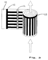
- An elongated film, on the two sides of which electrodes rows perpendicular to one another are applied, is closed rolled up in a roll.
- Insulating webs, which are applied to the electrodes on one side of the film in the direction of the roll axis, serve as spacers between the coiled layers, so that the suspension can flow through the roll along its figure axis.
- the desired particle type is extracted from the mixture by suitably applying a high-frequency AC voltage to the rows of electrodes on both sides.
- the elements delimiting the particle path have passable openings or are made of porous material.
- the outcoupled particles can escape from the flow channel through the openings.
- Such openings can be achieved particularly easily by using an ultra-thin membrane as the main body of the device, into which openings are etched.
- the electrode surfaces have relief-like structures, preferably longitudinal channels in the direction of the flow of the suspension medium. This avoids lateral deflection of the uncoupled, flowing particles and calms the flow. By calming the flow, the separation quality is increased.
- a further development of the invention according to claim 8 serves to influence the running properties of the flowing particles.
- the insulation layer on the electrodes which has locally different thicknesses, leaves the electric field different at different points act strongly on the particles. In this way, the particle flow can be manipulated effectively, since different preferred tracks for the particles can be created at different points in the device.
- the trough-shaped and undulating structure of the coating serves to calm and flexibly guide the particle flow.
- a device according to the invention preferably consists of materials which are used in microstructure technology and microelectronics and is produced using the methods customary there.
- the base body to which the electrodes are applied preferably consists of silicon, the electrodes of gold.
- the separation device is integrated together with an electronic circuit for controlling the electrodes and for evaluating the particle movement on a common base body, preferably a silicon wafer.
- the device according to the invention is well suited for cascading.
- the quality of separation is significantly increased by connecting several separating devices in series. Good results can be achieved if a decoupled partial stream is fed back to the output device and the cascade is run through again. In many cases, a very high separation quality is achieved when a decoupled partial stream is fed back by one or two separation stages.
- the advantages achieved with the invention are in particular in that the proposed separation of the mixture has a threshold value character in contrast to conventional separation processes.
- the separation therefore only depends on whether a certain type of particle can leave its management or not.
- the threshold value determining the separation can be chosen flexibly due to the easily influenceable relationship between the dielectric managers and the deflecting force components. This makes it easy to determine the type of particle to be coupled out and at the same time a high separation quality is achieved.
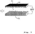
- the electrodes 31 and 32 enclose a flow channel 33.
- the incoming particle stream is indicated by an arrow.
- the mixture of particles is moved by the flow of the suspension medium through the device. Dielectrophoretic forces couple particles of a certain type out of the mixture in channel 33.
- the field inhomogeneities required for this are generated by the surface irregularities of the electrodes 31, 32.
- the type of particles to be coupled out is selected by the choice of the frequency and strength of the high-frequency alternating voltage U (f) applied between the electrodes 31, 32.
- the surfaces of the electrodes 31, 32 are structured by etching processes.
- FIG. 2 shows an electrode arrangement for coupling out particles from the stream of a suspended particle mixture.
- Two rows of electrodes 41, 42 enclose a flow channel 43 through which the suspended particle mixture represented by an arrow flows.
- the elongated electrodes 41, 42 of the two rows are arranged parallel to one another, unequally spaced apart. Adjacent electrodes in a row are connected to different poles of a high-frequency voltage source.
- the particles to be coupled out are selected by setting the applied field frequencies f1, f2 or via the selected voltages U1, U2.
- Electrode systems 52, 53 are applied on both sides to an elongated film 51. Both the electrodes 52 running parallel to the longitudinal direction of the film on one film surface and the electrodes 53 running perpendicular to the longitudinal direction of the film on the other film surface are conductively connected to one another at one end. Insulating bridges 54 are attached at regular intervals above the electrodes 52 and, after the film has been rolled up, prevent electrical contact between the electrode systems and keep flow-through spaces open for the flow of the suspended particle mixture. The flow of the particle mixture through the roller is indicated by arrows. Dielectrophoretic holding fields are used to couple out certain types of particles from the flowing mixture of particles. The holding fields are generated by applying a high-frequency AC voltage between the electrode systems.
- FIG. 4 shows a cascade-shaped separation section.
- Five separation devices (as shown, for example, in FIG. 2) are arranged one behind the other.
- the arrows 4 indicate that in this area, by combining the dielectrophoresis and an additional force, the particle mixture 1 is broken down into two fractions 2, 3.
- the fraction from the mixture decoupled particle type 2 passes through further separation stages for cleaning remaining particles of the mixture, in order to obtain the particles of type 2 remaining in fraction 3, particle fraction 3 is moved to the beginning of the cascade, for example, by an electrical, high-frequency traveling field 5 or one at a time Separation stage returned.
- a particularly high separation quality is achieved with the help of the cascade-shaped separation section.
Abstract
Description
Die Erfindung bezieht sich auf eine Vorrichtung zur Trennung von Gemischen mikroskopisch kleiner, dielektrischer Teilchen, bei welchen das Teilchengemisch in einer Flüssigkeit oder einem Gel suspendiert ist.The invention relates to a device for separating mixtures of microscopic dielectric particles, in which the particle mixture is suspended in a liquid or a gel.
Derartige Trennvorrichtungen sollen Gemische mikroskopisch kleiner Teilchen, wie biologische Zellen, Zellorganellen, Biomoleküle sowie anorganische, dielektrische Teilchen isolieren und für Untersuchungen oder technische Anwendungen aufbereiten.Separation devices of this type are intended to isolate mixtures of microscopic particles, such as biological cells, cell organelles, biomolecules and inorganic, dielectric particles, and to prepare them for investigations or technical applications.
Die Trennung bestimmter Teilchensorten aus Teilchengemischen ist beispielsweise in der Medizin, der Nahrungsmitteltechnologie, der Biologie, der Chemie und der Pharmazie erforderlich. Insbesondere wenn größere Mengen eines Gemisches getrennt werden sollen, ist es wünschenswert, ein kontinuierliches Trennverfahren einzusetzen.The separation of certain types of particles from particle mixtures is required, for example, in medicine, food technology, biology, chemistry and pharmacy. Especially when larger amounts of a mixture are to be separated, it is desirable to use a continuous separation process.
Zur Trennung von Teilchengemischen sind verschiedene elektrokinetische Verfahren bekannt. Trennverfahren wie zum Beispiel die Gelelektrophorese, die Isotachophorese und die isoelektrische Fokussierung trennen Teilchengemische nach den unterschiedlichen Beweglichkeiten ihrer Bestandteile auf. Eine entscheidende Voraussetzung für eine solche Auftrennung besteht darin, daß durch geeignete Maßnahmen die in jedem Fall auftretenden Konvektionen auf einen unkritischen Wert reduziert werden, da die Beweglichkeit der Teilchen durch die Konvektion beeinflußt wird.Various electrokinetic processes are known for separating particle mixtures. Separation processes such as gel electrophoresis, isotachophoresis and isoelectric focusing separate particle mixtures according to the different mobilities of their components. A crucial requirement For such a separation is that the convections that occur in any case are reduced to an uncritical value by suitable measures, since the mobility of the particles is influenced by the convection.
Die Reduzierung der Konvektion erfolgt entweder durch Kühlung oder durch die Verwendung konvektionsverhindernder Träger. Dabei sind Grenzen gesetzt, wenn relativ große Teilchen, wie biologische Zellen, zu trennen sind, oder wenn im kontinuierlichen Betrieb gearbeitet werden soll. Ein kontinuierlicher Betrieb kann deshalb nur durch aufwendige Kühltechniken oder durch komplizierte Stabilisierungstechniken, beispielsweise durch Nutzung von Zentrifugalkräften, erreicht werden.The convection is reduced either by cooling or by using convection-preventing carriers. There are limits when it comes to separating relatively large particles, such as biological cells, or when working in continuous operation. Continuous operation can therefore only be achieved by complex cooling techniques or by complicated stabilization techniques, for example by using centrifugal forces.
Die dabei anfallenden Kosten und technologischen Probleme haben dazu geführt, daß kontinuierlich arbeitende Elektrophoreseverfahren bislang nur in beschränktem Umfang Verwendung finden.The resulting costs and technological problems have meant that continuous electrophoresis processes have so far been used only to a limited extent.
Aus dem Aufsatz von M. Washizu, Electrostatic Manipulation of Biological Objects, erschienen in Journal of Electrostatics, Band 25, Nr. 1, Juni 1980, Amsterdam NL, Seiten 109 - 123 ist insbesondere auf den Seiten 119 und 120 ein Verfahren zum Trennen von Gemischen mikroskopisch kleiner, in einer Flüssigkeit oder einem Gel suspendierter dielektrischer Teilchen beschrieben. Die zu trennenden mikroskopisch kleinen Teilchen werden durch ein äußeres elektrisches Wechselfeld, das quer zur Bewegungsrichtung der Flüssigkeit bzw. des Gels angelegt ist, aufgetrennt. Das für die Auftrennung der Teilchen verwendete Hochfrequenzfeld wird jedoch nicht kontinuierlich betrieben, sondern es unterliegt einem charakteristischem Unterbrechungstakt, der konstruktionsbedingt ist und dafür sorgt, daß die einzelnen Zellen durch entsprechende Ausgänge die Trennvorrichtung verlassen können.From the article by M. Washizu, Electrostatic Manipulation of Biological Objects, published in Journal of Electrostatics, Volume 25, No. 1, June 1980, Amsterdam NL, pages 109-123, a method for separating in particular is on pages 119 and 120 Mixtures described microscopically smaller, in a liquid or a gel suspended dielectric particles. The microscopic particles to be separated are separated by an external alternating electric field, which is applied transversely to the direction of movement of the liquid or the gel. However, the high-frequency field used to separate the particles is not operated continuously, but is subject to a characteristic interruption cycle, which is design-related and ensures that the individual cells can leave the separating device through appropriate outputs.
Desweiteren geht aus der WO-92/97657 ein Verfahren zur Handhabung mikroskopisch kleiner, dieelektischer Teilchen und Vorrichtung zur Durchführung des Verfahrens hervor, das sich im wesentlichen auf Elektrodenanordnungen beschränkt, mit denen eine geradlinige, konzentrierte Teilchenführung innerhalb eines elektrischen Wechselfeldes möglich ist. So können mit den darin beschriebenen Elektrodenanordnungen mikroskopisch kleine, dielektrische Teilchen durch enge Kanäle auf geradlinigen Bahnen geführt werden, um sie zu verschiedenen Zielorten berührungsfrei für Untersuchungen zu positionieren.Furthermore, WO-92/97657 discloses a method for handling microscopic, dielectric particles and a device for carrying out the method, which is essentially limited to electrode arrangements with which a straight, concentrated particle guidance within an alternating electric field is possible. With the electrode arrangements described therein, microscopic, dielectric particles can be guided through narrow channels on straight lines in order to position them in a contact-free manner for examinations at different target locations.
Aus der WO-91 11 262 sind Elektrodenvorrichtungen bekannt, mit Hilfe derer mikrobiologische Teilchen, vorzugsweise Zellen aus einer Vorzugsrichtung, die durch die Strömung einer Trägerflüssigkeit vorgegeben ist, abzulenken. Mit Hilfe der in diesem Dokument beschriebenen Elektrodenanordnungen werden bestimmte Zellreaktionen angeregt und unterstützt, indem bestimmte Partikel räumlich in Kontakt gebracht werden. Hierzu sind die Elektrodenstrukturen entsprechend zu wählen, so daß Partikelansammlungen in bestimmten Bereichen möglich sind. Auch geht aus dieser Druckschrift die Verwendung zweier unabhängig voneinander angesteuerter Elektrodenpaare hervor, wie sie in den Figuren 7 a und b dargestellt sind. Beide Elektrodenpaare werden derart betrieben, so daß sich an ihren Elektrodenoberflächen bestimmte Teilchenpartikel anlagern können. Sind die Oberflächen vollständig mit den Partikeln überzogen, muß der Trennprozeß unterbrochen werden. Ferner bedarf die Anordnung eines strömenden Fluids, in dem die zu untersuchenden Partikel geführt werden.From WO-91 11 262 electrode devices are known, with the aid of which microbiological particles, preferably cells, are deflected from a preferred direction, which is predetermined by the flow of a carrier liquid. With the help of the electrode arrangements described in this document, certain cell reactions are stimulated and supported by bringing certain particles into spatial contact. For this purpose, the electrode structures must be selected accordingly, so that particle accumulations are possible in certain areas. This document also shows the use of two independently controlled electrode pairs, as shown in FIGS. 7 a and b. Both pairs of electrodes are operated in such a way that certain particle particles can accumulate on their electrode surfaces. If the surfaces are completely covered with the particles, the separation process must be interrupted. Furthermore, the arrangement of a flowing fluid in which the particles to be investigated.
In allen bekannten Druckschriften wird das Problem der Konvektion auf die mikrobiologischen Zellen nicht behandelt. Ferner ist bislang keine kontinuierlich arbeitende Trennvorrichtung bekannt, mit deren Hilfe die störenden Konvektionseinflüsse auf die zu trennenden Partikel gelöst ist.The problem of convection to the microbiological cells is not dealt with in all known publications. Furthermore, no continuously operating separation device is known so far, with the aid of which the disturbing convection influences on the particles to be separated are solved.
Der Erfindung liegt die Aufgabe zugrunde, eine Vorrichtung zur Trennung von Gemischen mikroskopisch kleiner, suspendierter Teilchen anzugeben, das kontinuierlich arbeitet, eine hohe Trenngüte aufweist und kostengünstig realisiert werden kann. Insbesondere soll, ohne großen gerätetechnischem Aufwand, mit Hilfe der Vorrichtung eine weitgehende Vermeidung der störenden Konvektionserscheinungen innerhalb der zu trennenden Teilchengemische ermöglicht werden.The invention has for its object to provide a device for separating mixtures of microscopically small, suspended particles, which operates continuously, has a high separation quality and can be implemented inexpensively. In particular, the device should be able to largely avoid the troublesome convection phenomena within the particle mixtures to be separated, without great expenditure on equipment.
Diese Aufgabe wird erfindungsgemäß mit einer Vorrichtung nach Anspruch 1 gelöst. Vorteilhafte Ausführungsformen sind den Ansprüchen 2ff zu entnehmen.This object is achieved with a device according to claim 1. Advantageous embodiments can be found in claims 2ff.
Die suspendierten Teilchen werden durch die Strömung eines Suspensionsmediums auf Führungsbahnen gezwungen.The suspended particles are forced onto guideways by the flow of a suspension medium.
Durch eine zusätzliche Kraft werden für bestimmte Teilchensorten die Kräfte, die die Teilchen auf die Führungsbahnen zwingen, kompensiert, so daß sie aus den Führungsbahnen ausgekoppelt und damit aus dem Gemisch getrennt werden.For certain types of particles, an additional force compensates for the forces which force the particles onto the guideways, so that they are decoupled from the guideways and thus separated from the mixture.
Das zusätzliche Kraftfeld wird durch eine hochfrequentes Wechselfeld bereitgestellt. Zur Vermeidung einer Ansammlung von dieelektrischen Teilchen an den Elektrodenoberflächen weisen die Elektroden Durchbrüche oder Poren auf, durch die die Teilchen abgeführt werden können. Auf diese Weise ist ein kontinuierlicher Betrieb möglich.The additional force field is due to a high frequency Alternating field provided. To avoid the accumulation of the electrical particles on the electrode surfaces, the electrodes have openings or pores through which the particles can be removed. In this way, continuous operation is possible.
Weiterbildungen und Ausgestaltungen der Erfindung sind in den Unteransprüchen gekennzeichnet.Further developments and refinements of the invention are characterized in the subclaims.
Die Auskopplung bestimmter Teilchensorten kann durch Variation des zusätzlichen Kraftfeldes oder durch Variation der durch das strömende Suspensionsmedium auf die Teilchen wirkenden Kraft je nach gewünschter Selektierung eingestellt werden.The decoupling of certain types of particles can be adjusted by varying the additional force field or by varying the force acting on the particles through the flowing suspension medium, depending on the desired selection.
Somit sieht die Vorrichtung als sogenanntes Führungsfeld ein, in eine vorgebbare Richtung strömendes Suspensionsmedium vor, das die zu trennenden Teilchen auf Führungsbahnen zwingt. Zusätzlich wirkt auf die Teilchen ein dielektrophoretisches Hochfrequenzfeld ein, das unter Kompensierung der durch die Strömung auf die Teilchen einwirkenden Kraft, diese aus der Strömung auskoppelt.The device thus provides a so-called guiding field, suspension medium flowing in a predeterminable direction, which forces the particles to be separated on guideways. In addition, a dielectrophoretic high-frequency field acts on the particles, which, while compensating for the force acting on the particles due to the flow, decouples them from the flow.
Entlang des Führungskanals sind Elektrodensysteme angeordnet, mit deren Hilfe im Strömungskanal inhomogene elektrische Wechselfelder erzeugt werden. Durch die Feldinhomogenitäten wirken auf die Teilchen dielektrophoretische Kräfte, die je nach Strömungsgeschwindigkeit und Feldstärke, bestimmte Teilchensorten aus dem Gemisch auskoppeln.Electrode systems are arranged along the guide channel, with the aid of which inhomogeneous electrical alternating fields are generated in the flow channel. Due to the field inhomogeneities, dielectrophoretic forces act on the particles, which, depending on the flow velocity and field strength, couple certain types of particles out of the mixture.
Nach Anspruch 2 werden die inhomogenen Felder mittels zweier parallel angeordneter Elektroden erzeugt, die den Strömungskanal einschließen, und deren einander zugewandte Oberflächen reliefartige Oberflächenirregularitäten wie Spitzen und Senken aufweisen. Die Auswahl der ausgekoppelten Teilchensorte erfolgt über die Frequenz oder Stärke der zwischen den Platten angelegten hochfrequenten Wechselspannung. Um eine Anlagerung der ausgekoppelten Teilchen auf den Elektroden zu verhindern, ist es vorteilhaft, das Elektrodenmaterial mit Durchbrüchen zu versehen, oder porös zu gestalten.According to
Nach Anspruch 3 werden die inhomogenen Felder mit Hilfe zweier parallel zueinander angeordneten Elektrodenreihen erzeugt, die den Strömungskanal einschließen. Die Feldinhomogenitäten werden dadurch erreicht, daß die Elektroden einer Reihe unterschiedlich beabstandet sind und zwischen benachbarten Elektroden einer Reihe Wechselspannungen angelegt werden, die sich hinsichtlich der Stärke und der Frequenz von den zwischen benachbarten Elektroden der anderen Reihe angelegten Spannungen unterscheiden.According to
Bei einer Weiterbildung der Erfindung gemäß Anspruch 4 sind verschiedene Elektrodensysteme auf zwei Seiten eines dünnen flexiblen Materials aufgebracht. Das flexible Material ist derart zu einer dreidimenionalen Struktur gefaltet oder gewickelt, daß Durchflußkanäle entstehen, die von Elektrodensystemen eingeschlossen sind.In a development of the invention according to
Eine weitere Ausgestaltung einer solchen Vorrichtung ist in Anspruch S gekennzeichnet. Eine langgestreckte Folie, auf deren beiden Seiten senkrecht zueinander stehende Elektrodenreihen aufgebracht sind, ist zu einer Rolle aufgewickelt. Isolierende Stege, die auf einer Seite der Folie in Richtung der Rollenachse auf den Elektroden aufgebracht sind, dienen als Abstandshalter zwischen den aufgewickelten Schichten, so daß die Rolle entlang ihrer Figurenachse von der Suspension durchströmt werden kann. Die Auskopplung der gewünschten Teilchensorte aus dem Gemisch erfolgt durch geeignete Beaufschlagung der beiderseitigen Elektrodenreihen mit einer hochfrequenten Wechselspannung.A further embodiment of such a device is characterized in claim S. An elongated film, on the two sides of which electrodes rows perpendicular to one another are applied, is closed rolled up in a roll. Insulating webs, which are applied to the electrodes on one side of the film in the direction of the roll axis, serve as spacers between the coiled layers, so that the suspension can flow through the roll along its figure axis. The desired particle type is extracted from the mixture by suitably applying a high-frequency AC voltage to the rows of electrodes on both sides.
Um zu verhindern, daß die aus dem Gemisch ausgekoppelten Teilchen die Strömung stören oder sich an den Elektroden ablagern, weisen die die Teilchenbahn begrenzenden Elemente nach Anspruch 6 passierbare Durchbrüche auf oder sind aus porösem Material gefertigt. Die ausgekoppelten Teilchen können durch die Öffnungen aus dem Strömungskanal entweichen. Besonders einfach lassen sich solche Öffnungen dadurch erzielen, daß als Grundkörper der Vorrichtung eine ultradünne Membrane verwendet wird, in die Durchbrüche geätzt werden.In order to prevent the particles extracted from the mixture from interfering with the flow or from being deposited on the electrodes, the elements delimiting the particle path have passable openings or are made of porous material. The outcoupled particles can escape from the flow channel through the openings. Such openings can be achieved particularly easily by using an ultra-thin membrane as the main body of the device, into which openings are etched.
Bei einer Vorrichtung gemäß Anspruch 7 weisen die Elektrodenflächen reliefartige Strukturen, vorzugsweise Längskanäle in Richtung der Strömung des Suspensionsmediums auf. Dadurch wird eine seitliche Ablenkung der nicht ausgekoppelten, strömenden Teilchen vermieden und die Strömung beruhigt. Durch die Beruhigung der Strömung wird eine Erhöhung der Trenngüte erreicht.In a device according to claim 7, the electrode surfaces have relief-like structures, preferably longitudinal channels in the direction of the flow of the suspension medium. This avoids lateral deflection of the uncoupled, flowing particles and calms the flow. By calming the flow, the separation quality is increased.
Eine Weiterbildung der Erfindung nach Anpruch 8 dient zur Beeinflussung der Laufeigenschaften der strömenden Teilchen. Die lokal unterschiedliche Dicken aufweisende Isolationsschicht auf den Elektroden läßt das elektrische Feld an verschiedenen Stellen unterschiedlich stark auf die Teilchen einwirken. Auf diese Weise kann der Teilchenstrom wirksam manipuliert werden, da an verschiedenen Stellen der Vorrichtung unterschiedliche Vorzugslaufbahnen für die Teilchen geschaffen werden können. Die mulden- und wellenförmige Struktur des Überzuges dient zur Beruhigung und flexiblen Führung des Teilchenstroms.A further development of the invention according to claim 8 serves to influence the running properties of the flowing particles. The insulation layer on the electrodes, which has locally different thicknesses, leaves the electric field different at different points act strongly on the particles. In this way, the particle flow can be manipulated effectively, since different preferred tracks for the particles can be created at different points in the device. The trough-shaped and undulating structure of the coating serves to calm and flexibly guide the particle flow.
Nach Anspruch 9 besteht eine erfindungsgemäße Vorrichtung vorzugsweise aus Materialien, die in der Mikrostrukturtechnik und der Mikroelektronik verwendet werden und wird mit den dort üblichen Verfahren hergestellt. Der Grundkörper, auf den die Elektroden aufgebracht werden, besteht vorzugsweise aus Silizium, die Elektroden aus Gold.According to claim 9, a device according to the invention preferably consists of materials which are used in microstructure technology and microelectronics and is produced using the methods customary there. The base body to which the electrodes are applied preferably consists of silicon, the electrodes of gold.
Nach Anspruch 10 wird die Trennvorrichtung gemeinsam mit einer elektronischen Schaltung zur Ansteuerung der Elektroden und zur Auswertung der Teilchenbewegung auf einem gemeinsamen Grundkörper, vorzugsweise einem Siliziumwafer, integriert.According to claim 10, the separation device is integrated together with an electronic circuit for controlling the electrodes and for evaluating the particle movement on a common base body, preferably a silicon wafer.
Die erfindungsgemäße Vorrichtung eignet sich gemäß Anspruch 11 gut für eine Kaskadierung. Durch Hintereinanderschalten mehrerer Trennvorrichtungen wird die Trenngüte wesentlich gesteigert. Gute Ergebnisse lassen sich erzielen, wenn ein ausgekoppelter Teilstrom auf die Ausgangsvorrichtung zurückgekoppelt wird und die Kaskade erneut durchläuft. In vielen Fällen wird eine sehr hohe Trenngüte bereits dann erreicht, wenn ein ausgekoppelter Teilstrom um eine oder zwei Trennstufen zurückgekoppelt wird.The device according to the invention is well suited for cascading. The quality of separation is significantly increased by connecting several separating devices in series. Good results can be achieved if a decoupled partial stream is fed back to the output device and the cascade is run through again. In many cases, a very high separation quality is achieved when a decoupled partial stream is fed back by one or two separation stages.
Die mit der Erfindung erzielten Vorteile bestehen insbesondere darin, daß die vorgeschlagene Auftrennung des Gemisches im Gegensatz zu üblichen Trennverfahren einen Schwellwertcharakter aufweist. Die Trennung hängt demnach nur davon ab, ob eine bestimmte Teilchensorte ihre Führung verlassen kann oder nicht. Der die Trennung bestimmende Schwellwert kann durch die leicht zu beeinflussende Beziehung zwischen den dielektrischen Führungskräften und den auslenkenden Kraftkomponenten flexibel gewählt werden. Dadurch kann die auszukoppelnde Teilchensorte einfach bestimmt werden und gleichzeitig wird eine hohe Trenngüte errreicht.The advantages achieved with the invention are in particular in that the proposed separation of the mixture has a threshold value character in contrast to conventional separation processes. The separation therefore only depends on whether a certain type of particle can leave its management or not. The threshold value determining the separation can be chosen flexibly due to the easily influenceable relationship between the dielectric managers and the deflecting force components. This makes it easy to determine the type of particle to be coupled out and at the same time a high separation quality is achieved.
Ausführungsbeispiele der Erfindung sind in den Zeichnungen schematisch dargestellt und werden im folgenden ohne Beschränkung des allgemeinen Erfindungsgedankens näher beschrieben. Es zeigen:
- Fig. 1
- ein Elektrodenpaar zur Auskopplung von Teilchen aus dem Strom eines suspendierten Teilchengemisches,
- Fig. 2
- eine Elektrodenanordnung zur Auskopplung von Teilchen aus dem Strom eines suspendierten Teilchengemisches,
- Fig. 3
- ein Teilchenfilter,
- Fig. 4
- eine Kaskadenanordnung.
- Fig. 1
- a pair of electrodes for coupling particles out of the stream of a suspended particle mixture,
- Fig. 2
- an electrode arrangement for coupling out particles from the stream of a suspended particle mixture,
- Fig. 3
- a particle filter,
- Fig. 4
- a cascade arrangement.
Die Fig. 1 zeigt ein Elektrodenpaar mit dessen Hilfe Teilchen aus dem Strom eines suspendierten Teilchengemisches ausgekoppelt werden. Die Elektroden 31 und 32 schließen einen Strömungskanal 33 ein. Der ankommende Teilchenstrom ist durch einen Pfeil angedeutet. Das Teilchengemisch wird durch die Strömung des Suspensionsmediums durch die Vorrichtung bewegt. Durch dielektrophoretische Kräfte werden Teilchen einer bestimmten Sorte im Kanal 33 aus dem Gemisch ausgekoppelt. Die hierzu erforderlichen Feldinhomogenitäten werden durch die Oberflächenirregularitäten der Elektroden 31, 32 erzeugt. Die Auswahl der auszukoppelnden Teilchensorte erfolgt durch die Wahl der Frequenz und Stärke der zwischen den Elektroden 31,32 angelegten hochfrequenten Wechselspannung U (f). Die Oberflächen der Elektroden 31, 32 werden durch Ätzverfahren strukturiert.1 shows a pair of electrodes with the aid of particles from the stream of a suspended particle mixture be coupled out. The
In Fig. 2 ist eine Elektrodenanordnung zur Auskopplung von Teilchen aus dem Strom eines suspendierten Teilchengemisches dargestellt. Zwei Reihen von Elektroden 41, 42 schließen einen Strömungskanal 43 ein, durch welchen das durch einen Pfeil dargestellte, suspendierte Teilchengemisch fließt. Die langgestreckten Elektroden 41, 42 der beiden Reihen sind parallel zueinander, ungleich abständig angeordnet. Jeweils benachbarte Elektroden einer Reihe sind mit verschiedenen Polen einer hochfrequenten Spannungsquelle verbunden. Durch die mittels der Elektroden 41, 42 erzeugten dielektrophoretischen Haltekräfte werden aus dem Teilchenstrom verschiedene Teilchensorten ausgekoppelt, wobei verschiedene Teilchensorten an verschiedenen Orten gehalten werden. Die Auswahl der auszukoppelnden Teilchen erfolgt durch Einstellung der angelegten Feldfrequenzen f1, f2, bzw. über die gewählten Spannungen U1, U2.2 shows an electrode arrangement for coupling out particles from the stream of a suspended particle mixture. Two rows of
Die Fig. 3 zeigt einen zu einer Rolle aufgewickelten Teilchenfilter, dessen Ende zur Verdeutlichung ausgewickelt ist. Auf einer langgestrecken Folie 51 sind beiseitig Elektrodensysteme 52, 53 aufgebracht. Sowohl die parallel zur Längsrichtung der Folie verlaufenden Elektroden 52 auf der einen Folienoberfläche, als auch der senkrecht zur Längsrichtung der Folie verlaufenden Elektroden 53 auf der anderen Folienoberfläche, sind an einem Ende miteinander leitend verbunden. Über den Elektroden 52 sind in regelmäßigen Abständen isolierende Brücken 54 angebracht, die nach dem Aufrollen der Folie einen elektrischen Kontakt zwischen den Elektrodensystemen unterbinden und Durchströmungsräume für den Strom des suspendierten Teilchengemisches offenhalten. Die Strömung des Teilchengemisches durch die Rolle ist durch Pfeile angedeutet. Durch dielektro-phoretische Haltefelder werden aus dem durchströmenden Teilchengemisch bestimmte Teilchensorten ausgekoppelt. Die Haltefelder werden durch Anlegen einer hochfrequenten Wechselspannung zwischen den Elektrodensystemen erzeugt.3 shows a particle filter wound up into a roll, the end of which is unwound for clarity.
Die Fig. 4 zeigt eine kaskadenförmige Trennstrecke. Fünf Trennvorrichtungen (wie z.B. in Fig. 2 dargestellt sind hintereinander angeordnet. Die Pfeile 4 deuten an, daß in diesem Bereich durch Kombination der Dielektrophorese und einer zusätzlichen Kraft das Teilchengemisch 1 in zwei Fraktionen 2, 3 zerlegt wird. Die Fraktion der aus dem Gemisch ausgekoppelten Teilchensorte 2 durchläuft zur Reinigung von verbliebenen Teilchen des Gemisches weitere Trennstufen. Um die in der Fraktion 3 verbliebenen Teilchen der Sorte 2 zu gewinnen, wird jeweils die Teilchenfraktion 3 beispielsweise durch ein elektrisches, hochfrequentes Wanderfeld 5 zum Anfang der Kaskade oder jeweils eine Trennstufe zurückgeführt. Mit Hilfe der kaskadenförmigen Trennstrecke wird eine besonders hohe Trenngüte erreicht.4 shows a cascade-shaped separation section. Five separation devices (as shown, for example, in FIG. 2) are arranged one behind the other. The
Claims (11)
dadurch gekennzeichnet, daß Elektroden entlang eines Strömungskanals angeordnet sind, in dem das Suspensionsmedium strömt, und zur Erzeugung eines Kraftfeldes mit einer oder mehreren Hochfrequenz-Spannungsquellen verbunden und derart ausgebildet sind, daß die erzeugten elektrischen Felder im Bereich des Strömungskanal Inhomogenitäten aufweisen und, daß die Elektroden passierbare Durchbrüche oder Poren aufweisen.Device for separating mixtures of microscopic dielectric particles suspended in a liquid or gel,
characterized in that electrodes are arranged along a flow channel in which the suspension medium flows, and are connected to one or more high-frequency voltage sources in order to generate a force field and are designed in such a way that the generated electric fields in the region of the flow channel have inhomogeneities and that Electrodes have passable openings or pores.
dadurch gekennzeichnet, daß die Elektroden Oberflächen mit reliefartigen Irregularitäten aufweisen.Device according to claim 1,
characterized in that the electrodes have surfaces with relief-like irregularities.
dadurch gekennzeichnet, daß die Elektroden (41,42) reihenhaft entlang der Strömungsrichtung parallel zueinander angeordnet und unterschiedlich voneinander beabstandet sind und daß die Elektroden (41,42) jeder Reihe derart mit einer Hochfrequenz-Spannungsquelle U1, U2 verbunden sind, daß jeweils zwei benachbarte Elektroden mit verschiedenen Polen der Spannungsquelle elektrisch verbunden sind.Device according to claim 1,
characterized in that the electrodes (41, 42) are arranged in rows along the flow direction parallel to one another and spaced differently from one another, and in that the electrodes (41, 42) in each row are connected to a high-frequency voltage source U1, U2 such that two adjacent ones Electrodes are electrically connected to different poles of the voltage source.
dadurch gekennzeichnet, daß die zur Erzeugung der dielektrophoretischen Kräfte vorgesehenen Elektrodensysteme auf die beiden Seiten eines dünnen, flexiblen Materials aufgebracht sind, das derart zu einer dreidimensionalen Struktur gefaltet oder gewickelt ist, daß sich Durchflußkanäle ergeben, die von den Elektrodensystemen eingeschlossen sind.Device according to one of claims 1 to 3,
characterized in that the electrode systems provided to generate the dielectrophoretic forces are on both sides of a thin, flexible material are applied, which is folded or wound into a three-dimensional structure in such a way that flow channels result which are enclosed by the electrode systems.
dadurch gekennzeichnet, daß auf einer Seite einer langgestreckten Folie (51) eine Reihe in Längsrichtung der Folie verlaufende Elektroden (52) aufgebracht sind, die an einem Ende miteinander verbunden sind, daß auf den Elektroden in regelmäßigen Abständen isolierende Stege (54) aufgebracht sind, daß auf der anderen Seite der Folie (51) quer zur Längsrichtung der Folie verlaufende Elektroden (53) aufgebracht sind, die an einem Ende leitend miteinander verbunden sind, daß die Folie (51) derart in Längsrichtung aufgewickelt ist, daß die isolierenden Stege (54) als Abstandshalter zwischen den Schichten der aufgewickelten Folie dienen, und daß zwischen den auf den beiden Seiten der Folie (51) aufgebrachten Elektrodensystemen (52,53) eine hochfrequente Wechselspannung angelegt ist.Device according to claim 4,
characterized in that a row of electrodes (52) extending in the longitudinal direction of the film are applied to one side of an elongated film (51) and are connected to one another at one end in that insulating webs (54) are applied to the electrodes at regular intervals, that electrodes (53) extending transversely to the longitudinal direction of the film are applied to the other side of the film (51) and are conductively connected to one another at one end, that the film (51) is wound in the longitudinal direction in such a way that the insulating webs (54 ) serve as a spacer between the layers of the wound film, and that a high-frequency alternating voltage is applied between the electrode systems (52, 53) applied to the two sides of the film (51).
dadurch gekennzeichnet, daß die die Teilchenbahnen begrenzenden Elemente passierbare Durchbrüche oder Poren aufweisen.Device according to one of claims 1 to 5,
characterized in that the elements delimiting the particle tracks have passable openings or pores.
dadurch gekennzeichnet, daß die Elektrodenoberflächen eine in mikroskopischer Dimension reliefartige Oberflächenstruktur derart aufweisen, daß in Richtung des Teilchenstroms Längskanäle ausgebildet sind.Device according to one of claims 1 to 6,
characterized in that the electrode surfaces have a surface structure that is relief-like in microscopic dimension in such a way that longitudinal channels are formed in the direction of the particle flow.
dadurch gekennzeichnet, daß die Elektrodenoberflächen mit isolierenden Materialien überzogen sind, und daß der Überzug Mulden, Wellen oder Bereiche unterschiedlicher Stärke aufweist.Device according to one of claims 1 to 7,
characterized in that the electrode surfaces are coated with insulating materials and that the coating has troughs, waves or areas of different thickness.
dadurch gekennzeichnet, daß der die Elektroden tragende Grundkörper aus halbleitendem Material, Glas oder Keramik besteht, daß die partiellen Vertiefungen, Erhöhungen oder Durchbrüche durch Ätzverfahren erzeugt sind, daß die Elektroden aus einem chemisch inerten Material bestehen, mit photolithographischen Methoden strukturiert und galvanisch abgeformt sind, und daß die dielektrischen Schichten auf den Elektroden aus SiO₂, Si₃N₄, Bariumtitanat oder TiO₂ bestehen.Device according to one of claims 1 to 8,
characterized in that the base body carrying the electrodes consists of semiconducting material, glass or ceramic, that the partial depressions, elevations or breakthroughs are produced by etching processes, that the electrodes consist of a chemically inert material, are structured with photolithographic methods and are galvanically molded, and that the dielectric layers on the electrodes consist of SiO₂, Si₃N₄, barium titanate or TiO₂.
dadurch gekennzeichnet, daß das Multielektrodensystem zur Trennung der Teilchen zusammen mit einer elektronischen Schaltung zur Erzeugung der Felder und zur Auswertung von Teilchenbewegungen auf einem gemeinsamen Grundkörper integriert ist.Device according to one of claims 1 to 9,
characterized in that the multi-electrode system for separating the particles is integrated together with an electronic circuit for generating the fields and for evaluating particle movements on a common base body.
dadurch gekennzeichnet, daß mehrere Vorrichtungen kaskadenförmig hintereinander angeordnet sind.Device according to one of claims 1 to 10,
characterized in that several devices are arranged in cascade one behind the other.
Applications Claiming Priority (3)
| Application Number | Priority Date | Filing Date | Title |
|---|---|---|---|
| DE4127405 | 1991-08-19 | ||
| DE4127405A DE4127405C2 (en) | 1991-08-19 | 1991-08-19 | Process for the separation of mixtures of microscopic dielectric particles suspended in a liquid or a gel and device for carrying out the process |
| EP92918105A EP0599957B1 (en) | 1991-08-19 | 1992-08-19 | Process for the continuous separation of mixtures of microscopically small dielectric particles and device for implementing the process |
Related Parent Applications (2)
| Application Number | Title | Priority Date | Filing Date |
|---|---|---|---|
| EP92918105.5 Division | 1992-08-19 | ||
| EP92918105A Division EP0599957B1 (en) | 1991-08-19 | 1992-08-19 | Process for the continuous separation of mixtures of microscopically small dielectric particles and device for implementing the process |
Publications (3)
| Publication Number | Publication Date |
|---|---|
| EP0718038A2 true EP0718038A2 (en) | 1996-06-26 |
| EP0718038A3 EP0718038A3 (en) | 1996-08-28 |
| EP0718038B1 EP0718038B1 (en) | 2002-10-09 |
Family
ID=6438619
Family Applications (2)
| Application Number | Title | Priority Date | Filing Date |
|---|---|---|---|
| EP96103459A Expired - Lifetime EP0718038B1 (en) | 1991-08-19 | 1992-08-19 | Apparatus for separating mixtures of microscopic small dielectric particles dispersed in a fluid or a gel |
| EP92918105A Expired - Lifetime EP0599957B1 (en) | 1991-08-19 | 1992-08-19 | Process for the continuous separation of mixtures of microscopically small dielectric particles and device for implementing the process |
Family Applications After (1)
| Application Number | Title | Priority Date | Filing Date |
|---|---|---|---|
| EP92918105A Expired - Lifetime EP0599957B1 (en) | 1991-08-19 | 1992-08-19 | Process for the continuous separation of mixtures of microscopically small dielectric particles and device for implementing the process |
Country Status (5)
| Country | Link |
|---|---|
| US (1) | US5454472A (en) |
| EP (2) | EP0718038B1 (en) |
| JP (1) | JP3453136B2 (en) |
| DE (4) | DE4127405C2 (en) |
| WO (1) | WO1993003850A1 (en) |
Cited By (22)
| Publication number | Priority date | Publication date | Assignee | Title |
|---|---|---|---|---|
| WO2005021151A1 (en) * | 2003-08-27 | 2005-03-10 | President And Fellows Of Harvard College | Electronic control of fluidic species |
| EP1583956A2 (en) * | 2002-12-20 | 2005-10-12 | The Board Of Regents, The University Of Texas System | Methods and apparatus for electrosmear analysis |
| US9017623B2 (en) | 2007-02-06 | 2015-04-28 | Raindance Technologies, Inc. | Manipulation of fluids and reactions in microfluidic systems |
| US9068699B2 (en) | 2007-04-19 | 2015-06-30 | Brandeis University | Manipulation of fluids, fluid components and reactions in microfluidic systems |
| US9228229B2 (en) | 2010-02-12 | 2016-01-05 | Raindance Technologies, Inc. | Digital analyte analysis |
| US9328344B2 (en) | 2006-01-11 | 2016-05-03 | Raindance Technologies, Inc. | Microfluidic devices and methods of use in the formation and control of nanoreactors |
| US9366632B2 (en) | 2010-02-12 | 2016-06-14 | Raindance Technologies, Inc. | Digital analyte analysis |
| US9562837B2 (en) | 2006-05-11 | 2017-02-07 | Raindance Technologies, Inc. | Systems for handling microfludic droplets |
| US10351905B2 (en) | 2010-02-12 | 2019-07-16 | Bio-Rad Laboratories, Inc. | Digital analyte analysis |
| US10639597B2 (en) | 2006-05-11 | 2020-05-05 | Bio-Rad Laboratories, Inc. | Microfluidic devices |
| US10647981B1 (en) | 2015-09-08 | 2020-05-12 | Bio-Rad Laboratories, Inc. | Nucleic acid library generation methods and compositions |
| US10732649B2 (en) | 2004-07-02 | 2020-08-04 | The University Of Chicago | Microfluidic system |
| US11077415B2 (en) | 2011-02-11 | 2021-08-03 | Bio-Rad Laboratories, Inc. | Methods for forming mixed droplets |
| US11168353B2 (en) | 2011-02-18 | 2021-11-09 | Bio-Rad Laboratories, Inc. | Compositions and methods for molecular labeling |
| US11174509B2 (en) | 2013-12-12 | 2021-11-16 | Bio-Rad Laboratories, Inc. | Distinguishing rare variations in a nucleic acid sequence from a sample |
| US11187702B2 (en) | 2003-03-14 | 2021-11-30 | Bio-Rad Laboratories, Inc. | Enzyme quantification |
| US11390917B2 (en) | 2010-02-12 | 2022-07-19 | Bio-Rad Laboratories, Inc. | Digital analyte analysis |
| US11511242B2 (en) | 2008-07-18 | 2022-11-29 | Bio-Rad Laboratories, Inc. | Droplet libraries |
| US11635427B2 (en) | 2010-09-30 | 2023-04-25 | Bio-Rad Laboratories, Inc. | Sandwich assays in droplets |
| US11786872B2 (en) | 2004-10-08 | 2023-10-17 | United Kingdom Research And Innovation | Vitro evolution in microfluidic systems |
| US11901041B2 (en) | 2013-10-04 | 2024-02-13 | Bio-Rad Laboratories, Inc. | Digital analysis of nucleic acid modification |
| US11898193B2 (en) | 2011-07-20 | 2024-02-13 | Bio-Rad Laboratories, Inc. | Manipulating droplet size |
Families Citing this family (124)
| Publication number | Priority date | Publication date | Assignee | Title |
|---|---|---|---|---|
| GB9301122D0 (en) * | 1993-01-21 | 1993-03-10 | Scient Generics Ltd | Method of analysis/separation |
| GB9306729D0 (en) * | 1993-03-31 | 1993-05-26 | British Tech Group | Improvements in separators |
| DE4400955C2 (en) * | 1993-12-23 | 1999-04-01 | Fraunhofer Ges Forschung | Adhesion-controllable surface structure |
| US5514150A (en) * | 1994-03-03 | 1996-05-07 | Lsi Logic Corporation | Micromachined conveyor devices |
| FR2720505B1 (en) * | 1994-05-24 | 1996-07-05 | Commissariat Energie Atomique | High sensitivity charged particle selector. |
| US5645702A (en) * | 1995-06-07 | 1997-07-08 | Hewlett-Packard Company | Low voltage miniaturized column analytical apparatus and method |
| DE19500683B4 (en) * | 1994-12-10 | 2007-03-22 | Fraunhofer-Gesellschaft zur Förderung der angewandten Forschung e.V. | Trapping of molecules and microparticles in field cages |
| US5626734A (en) * | 1995-08-18 | 1997-05-06 | University Technologies International, Inc. | Filter for perfusion cultures of animal cells and the like |
| DE19545370C1 (en) * | 1995-12-05 | 1997-06-12 | Fraunhofer Ges Forschung | Assembly and joining method for dielectric micro-components |
| DE69737552T2 (en) * | 1996-01-31 | 2007-12-13 | The Board of Regents, The University of Texas System, Austin | FRACTIONATION BY DIELECTROPHORESIS AND FRACTIONATION USING A FLOW FIELD |
| US5993630A (en) * | 1996-01-31 | 1999-11-30 | Board Of Regents The University Of Texas System | Method and apparatus for fractionation using conventional dielectrophoresis and field flow fractionation |
| US5888370A (en) * | 1996-02-23 | 1999-03-30 | Board Of Regents, The University Of Texas System | Method and apparatus for fractionation using generalized dielectrophoresis and field flow fractionation |
| NZ331865A (en) * | 1996-03-18 | 1999-04-29 | Univ Wales Bangor Change Of Na | Apparatus with electrode arrays for carrying out chemical, physical or physico-chemical reactions |
| GB9615775D0 (en) * | 1996-07-26 | 1996-09-04 | British Tech Group | Apparatus and method for characterising particles using dielectrophoresis |
| GB9619093D0 (en) | 1996-09-12 | 1996-10-23 | Scient Generics Ltd | Methods of analysis/separation |
| US6221654B1 (en) * | 1996-09-25 | 2001-04-24 | California Institute Of Technology | Method and apparatus for analysis and sorting of polynucleotides based on size |
| US5858192A (en) * | 1996-10-18 | 1999-01-12 | Board Of Regents, The University Of Texas System | Method and apparatus for manipulation using spiral electrodes |
| US5972190A (en) * | 1996-11-19 | 1999-10-26 | Mcdonnell Douglas Corporation | Continuous flow electrophoresis apparatus |
| US6540895B1 (en) | 1997-09-23 | 2003-04-01 | California Institute Of Technology | Microfabricated cell sorter for chemical and biological materials |
| US7214298B2 (en) * | 1997-09-23 | 2007-05-08 | California Institute Of Technology | Microfabricated cell sorter |
| US6211477B1 (en) | 1998-02-26 | 2001-04-03 | Becton Dickinson And Company | Electrostatic deceleration system for flow cytometer |
| US5988432A (en) * | 1998-03-25 | 1999-11-23 | Sarnoff Corporation | Bead manipulating chucks with bead size selector |
| DE19815882A1 (en) | 1998-04-08 | 1999-10-14 | Fuhr Guenther | Method and device for manipulating microparticles in fluid flows |
| AU4546899A (en) * | 1998-06-05 | 1999-12-20 | Sarnoff Corporation | Apparatus for separating molecules |
| WO2000023193A1 (en) | 1998-10-20 | 2000-04-27 | William Whitelaw | Particle separator and method of separating particles |
| US6294063B1 (en) * | 1999-02-12 | 2001-09-25 | Board Of Regents, The University Of Texas System | Method and apparatus for programmable fluidic processing |
| US6858439B1 (en) | 1999-03-15 | 2005-02-22 | Aviva Biosciences | Compositions and methods for separation of moieties on chips |
| GB9908099D0 (en) * | 1999-04-12 | 1999-06-02 | Gay Geoffrey N W | Air cleaning collection device |
| US6537433B1 (en) * | 2000-03-10 | 2003-03-25 | Applera Corporation | Methods and apparatus for the location and concentration of polar analytes using an alternating electric field |
| EP1263532A2 (en) * | 2000-03-16 | 2002-12-11 | Sri International | Microlaboratory devices and methods |
| JP4587112B2 (en) * | 2000-04-13 | 2010-11-24 | 和光純薬工業株式会社 | Dielectrophoresis apparatus and material separation method |
| GB2361883B (en) * | 2000-05-03 | 2003-05-28 | Cell Analysis Ltd | Method and apparatus for analysing low concentrations of particles |
| US7351376B1 (en) | 2000-06-05 | 2008-04-01 | California Institute Of Technology | Integrated active flux microfluidic devices and methods |
| WO2001096024A2 (en) * | 2000-06-14 | 2001-12-20 | Board Of Regents, The University Of Texas System | Apparatus and method for fluid injection |
| ATE304174T1 (en) * | 2000-06-14 | 2005-09-15 | Univ Texas | SYSTEMS AND METHODS FOR CELL PART POPULATION ANALYSIS |
| CA2413634A1 (en) * | 2000-06-14 | 2001-12-20 | Peter R. C. Gascoyne | Method and apparatus for combined magnetophoretic and dielectrophoretic manipulation of analyte mixtures |
| US6329623B1 (en) * | 2000-06-23 | 2001-12-11 | Outokumpu Oyj | Electrostatic separation apparatus and method using box-shaped electrodes |
| US6829753B2 (en) | 2000-06-27 | 2004-12-07 | Fluidigm Corporation | Microfluidic design automation method and system |
| AU2000274922A1 (en) * | 2000-08-08 | 2002-02-18 | Aviva Biosciences Corporation | Methods for manipulating moieties in microfluidic systems |
| EP1334347A1 (en) | 2000-09-15 | 2003-08-13 | California Institute Of Technology | Microfabricated crossflow devices and methods |
| CN1325909C (en) * | 2000-09-27 | 2007-07-11 | 清华大学 | Apparatus for particle operation and guide and use method thereof |
| AU1189702A (en) | 2000-10-13 | 2002-04-22 | Fluidigm Corp | Microfluidic device based sample injection system for analytical devices |
| US6685812B2 (en) * | 2001-01-09 | 2004-02-03 | The Regents Of The University Of California | Movement of particles using sequentially activated dielectrophoretic particle trapping |
| US6443704B1 (en) * | 2001-03-02 | 2002-09-03 | Jafar Darabi | Electrohydrodynamicly enhanced micro cooling system for integrated circuits |
| AU2002307152A1 (en) | 2001-04-06 | 2002-10-21 | California Institute Of Technology | Nucleic acid amplification utilizing microfluidic devices |
| EP1384067B1 (en) * | 2001-05-02 | 2007-07-18 | Applera Corporation | Concentration and purification of analytes using electric fields |
| US7419574B2 (en) * | 2001-06-20 | 2008-09-02 | Cummings Eric B | Dielectrophoresis device and method having non-uniform arrays for manipulating particles |
| JP3695431B2 (en) * | 2001-08-03 | 2005-09-14 | 日本電気株式会社 | Separation apparatus and method of manufacturing separation apparatus |
| US8440093B1 (en) | 2001-10-26 | 2013-05-14 | Fuidigm Corporation | Methods and devices for electronic and magnetic sensing of the contents of microfluidic flow channels |
| US6703819B2 (en) | 2001-12-03 | 2004-03-09 | Board Of Regents, The University Of Texas System | Particle impedance sensor |
| US20030119057A1 (en) * | 2001-12-20 | 2003-06-26 | Board Of Regents | Forming and modifying dielectrically-engineered microparticles |
| US6866762B2 (en) * | 2001-12-20 | 2005-03-15 | Board Of Regents, University Of Texas System | Dielectric gate and methods for fluid injection and control |
| JP3811404B2 (en) * | 2002-01-10 | 2006-08-23 | 独立行政法人科学技術振興機構 | Dielectrophoresis filter device and method for removing suspended fine particles by dielectrophoresis |
| EP1499706A4 (en) | 2002-04-01 | 2010-11-03 | Fluidigm Corp | Microfluidic particle-analysis systems |
| JP2006507921A (en) | 2002-06-28 | 2006-03-09 | プレジデント・アンド・フェロウズ・オブ・ハーバード・カレッジ | Method and apparatus for fluid dispersion |
| US20040011652A1 (en) * | 2002-07-16 | 2004-01-22 | Bressler Vincent Edward | Separation of particles using multiple conductive layers |
| US6911132B2 (en) * | 2002-09-24 | 2005-06-28 | Duke University | Apparatus for manipulating droplets by electrowetting-based techniques |
| US7329545B2 (en) | 2002-09-24 | 2008-02-12 | Duke University | Methods for sampling a liquid flow |
| EP1551753A2 (en) | 2002-09-25 | 2005-07-13 | California Institute Of Technology | Microfluidic large scale integration |
| JP5695287B2 (en) | 2002-10-02 | 2015-04-01 | カリフォルニア インスティテュート オブ テクノロジー | Nucleic acid analysis of microfluids |
| US7063777B2 (en) * | 2002-12-12 | 2006-06-20 | Aura Biosystems Inc. | Dielectrophoretic particle profiling system and method |
| JP2004243238A (en) * | 2003-02-14 | 2004-09-02 | National Institute Of Advanced Industrial & Technology | Particle sorting method |
| DE10311716A1 (en) * | 2003-03-17 | 2004-10-14 | Evotec Oai Ag | Method and device for separating particles in a liquid flow |
| GB0307403D0 (en) | 2003-03-31 | 2003-05-07 | Medical Res Council | Selection by compartmentalised screening |
| GB0307428D0 (en) | 2003-03-31 | 2003-05-07 | Medical Res Council | Compartmentalised combinatorial chemistry |
| US20060078893A1 (en) | 2004-10-12 | 2006-04-13 | Medical Research Council | Compartmentalised combinatorial chemistry by microfluidic control |
| EP1610888A2 (en) | 2003-04-10 | 2006-01-04 | President And Fellows Of Harvard College | Formation and control of fluidic species |
| US7169282B2 (en) * | 2003-05-13 | 2007-01-30 | Aura Biosystems Inc. | Dielectrophoresis apparatus |
| US7413712B2 (en) | 2003-08-11 | 2008-08-19 | California Institute Of Technology | Microfluidic rotary flow reactor matrix |
| US7347923B2 (en) * | 2003-10-03 | 2008-03-25 | Sandia Corporation | Dielectrophoresis device and method having insulating ridges for manipulating particles |
| JP2005334865A (en) * | 2004-01-19 | 2005-12-08 | Hiroshima Univ | Solid particle classifier and solid particle classification method utilizing the same |
| US7384791B2 (en) * | 2004-01-21 | 2008-06-10 | Hewlett-Packard Development Company, L.P. | Method of analyzing blood |
| US7390387B2 (en) * | 2004-03-25 | 2008-06-24 | Hewlett-Packard Development Company, L.P. | Method of sorting cells in series |
| US7160425B2 (en) * | 2004-03-25 | 2007-01-09 | Hewlett-Packard Development Company, L.P. | Cell transporter for a biodevice |
| US7390388B2 (en) * | 2004-03-25 | 2008-06-24 | Hewlett-Packard Development Company, L.P. | Method of sorting cells on a biodevice |
| US20050221339A1 (en) | 2004-03-31 | 2005-10-06 | Medical Research Council Harvard University | Compartmentalised screening by microfluidic control |
| US8974652B2 (en) * | 2004-05-28 | 2015-03-10 | Board Of Regents, The University Of Texas System | Programmable fluidic processors |
| FR2871070B1 (en) * | 2004-06-02 | 2007-02-16 | Commissariat Energie Atomique | MICRODISPOSITIVE AND EMULSION SEPARATION PROCESS |
| US8329015B2 (en) * | 2004-06-16 | 2012-12-11 | Ares Trading S.A. | Dielectrophoretic process for retaining polarizable target-particles and device for performing that process |
| JP4599566B2 (en) * | 2004-08-31 | 2010-12-15 | 国立大学法人 新潟大学 | Electrical detection of nonpolar complex molecular motion using inhomogeneous electric fields |
| WO2007044029A2 (en) * | 2004-12-03 | 2007-04-19 | Nano Science Diagnostic, Inc. | Method and apparatus for low quantity detection of bioparticles in small sample volumes |
| WO2006063625A1 (en) * | 2004-12-17 | 2006-06-22 | Agilent Technologies, Inc. | Fractionation using electro elution |
| EP1859330B1 (en) | 2005-01-28 | 2012-07-04 | Duke University | Apparatuses and methods for manipulating droplets on a printed circuit board |
| CA2599683A1 (en) | 2005-03-04 | 2006-09-14 | President And Fellows Of Harvard College | Method and apparatus for forming multiple emulsions |
| DE102005012128A1 (en) * | 2005-03-16 | 2006-09-21 | Evotec Technologies Gmbh | Microfluidic system and associated driving method |
| US7998328B2 (en) * | 2005-06-27 | 2011-08-16 | Cfd Research Corporation | Method and apparatus for separating particles by dielectrophoresis |
| JP2009014342A (en) * | 2005-10-19 | 2009-01-22 | Sharp Corp | Electrophoretic chip, electrophoretic device and electrophoretic system |
| WO2007046484A1 (en) * | 2005-10-19 | 2007-04-26 | Sharp Kabushiki Kaisha | Electrophoretic chip, electrophoretic device, and electrophoretic system |
| JP4760330B2 (en) * | 2005-11-25 | 2011-08-31 | 富士ゼロックス株式会社 | Fine particle classification method and classification device |
| DE102006023238A1 (en) * | 2006-05-18 | 2007-11-22 | Universität Tübingen | Contact-free fixing, positioning, manipulating, releasing and/or removing of particles between electrodes in a medium for sorting, and/or disposing of fine particulate, comprises placing an electric signal sequence on the electrodes |
| KR100813254B1 (en) | 2006-05-29 | 2008-03-13 | 삼성전자주식회사 | An apparatus for separating a polarizable analyte using dielectrophoresis and a method of separating a polarizable analyte using the same |
| WO2008021123A1 (en) | 2006-08-07 | 2008-02-21 | President And Fellows Of Harvard College | Fluorocarbon emulsion stabilizing surfactants |
| ATE472372T1 (en) * | 2006-10-26 | 2010-07-15 | Imec | HANDLING MAGNETIC OR MAGNETIZABLE OBJECTS USING COMBINED MAGNETOPHORESIS AND DIELECTROPHORESIS |
| US8702945B2 (en) * | 2007-05-18 | 2014-04-22 | University Of Washington | Time-varying flows for microfluidic particle separation |
| US8702946B1 (en) | 2007-05-31 | 2014-04-22 | Sandia Corporation | Dielectrokinetic chromatography and devices thereof |
| US20090205962A1 (en) * | 2007-07-11 | 2009-08-20 | West Virginia University | Electrophoresis device and method |
| US8268246B2 (en) * | 2007-08-09 | 2012-09-18 | Advanced Liquid Logic Inc | PCB droplet actuator fabrication |
| US7655124B2 (en) * | 2007-10-05 | 2010-02-02 | Mady Attila | Apparatus to assist platelet manipulation to prevent and treat endovascular disease and its sequelae |
| GB0812996D0 (en) * | 2008-07-16 | 2008-08-20 | Blood Analysis Ltd | Electrode arrangement for analysing concentrations of particles |
| JP4674625B2 (en) * | 2008-09-25 | 2011-04-20 | 富士ゼロックス株式会社 | Classification device and classification method |
| EP3415235A1 (en) | 2009-03-23 | 2018-12-19 | Raindance Technologies Inc. | Manipulation of microfluidic droplets |
| US9757698B2 (en) | 2009-06-26 | 2017-09-12 | President And Fellows Of Harvard College | Fluid injection |
| EP2473263B1 (en) | 2009-09-02 | 2022-11-02 | President and Fellows of Harvard College | Multiple emulsions created using jetting and other techniques |
| WO2011042564A1 (en) | 2009-10-09 | 2011-04-14 | Universite De Strasbourg | Labelled silica-based nanomaterial with enhanced properties and uses thereof |
| EP2517025B1 (en) | 2009-12-23 | 2019-11-27 | Bio-Rad Laboratories, Inc. | Methods for reducing the exchange of molecules between droplets |
| US8658056B1 (en) | 2010-05-05 | 2014-02-25 | The United States Of America As Represented By The Secretary Of The Air Force | Harvesting single domain nanoparticles and their applications |
| WO2012162296A2 (en) | 2011-05-23 | 2012-11-29 | President And Fellows Of Harvard College | Control of emulsions, including multiple emulsions |
| US8841071B2 (en) | 2011-06-02 | 2014-09-23 | Raindance Technologies, Inc. | Sample multiplexing |
| WO2013006661A2 (en) | 2011-07-06 | 2013-01-10 | President And Fellows Of Harvard College | Multiple emulsions and techniques for the formation of multiple emulsions |
| KR101356460B1 (en) | 2012-02-08 | 2014-02-04 | 서울대학교산학협력단 | Particle Separation Device and method of separating particle from solution using the same |
| JP5924276B2 (en) * | 2012-04-03 | 2016-05-25 | ソニー株式会社 | Channel device, particle sorting apparatus, and particle sorting method |
| KR101453500B1 (en) * | 2013-01-17 | 2014-10-23 | 한국기계연구원 | Electrostatic coagulation apparatus for growth of water droplets in water-dispersed emulsions |
| JP5628971B1 (en) * | 2013-06-13 | 2014-11-19 | 日本写真印刷株式会社 | Microfluidic device and dielectrophoresis apparatus |
| KR101451383B1 (en) * | 2013-08-07 | 2014-10-22 | 한국과학기술연구원 | Particle Control Device |
| US11193176B2 (en) | 2013-12-31 | 2021-12-07 | Bio-Rad Laboratories, Inc. | Method for detecting and quantifying latent retroviral RNA species |
| JP6436955B2 (en) * | 2016-02-02 | 2018-12-12 | 国立研究開発法人科学技術振興機構 | Particle sorting apparatus and particle sorting method |
| CN107262288B (en) * | 2017-07-27 | 2023-03-21 | 重庆科技学院 | Electrostatic purification device with metal particles |
| US11260330B2 (en) | 2018-02-09 | 2022-03-01 | Paul NEISER | Filtration apparatus and method |
| KR20200138187A (en) | 2018-02-09 | 2020-12-09 | 폴 네이저 | Filter device and method |
| EP3752876A1 (en) * | 2018-02-15 | 2020-12-23 | Neiser, Paul | Apparatus and methods for selectively transmitting objects |
| DE102018211001A1 (en) * | 2018-07-04 | 2020-01-09 | Robert Bosch Gmbh | Device for dielectrophoretic capture of particles |
| KR102089342B1 (en) * | 2018-11-13 | 2020-04-20 | (주)아프로텍 | Precipitation Device having Dielectrophoresis Particle Separating Module |
| US20230158488A1 (en) * | 2020-04-08 | 2023-05-25 | Indiana Biosciences Research Institute, Inc. | System and Method for Sensing, Capture and Release of Biomolecules or Cells |
| KR20230138265A (en) * | 2022-03-23 | 2023-10-05 | 한국핵융합에너지연구원 | Sorting apparatus for dielectric powder |
Citations (3)
| Publication number | Priority date | Publication date | Assignee | Title |
|---|---|---|---|---|
| JPS60129150A (en) * | 1983-12-15 | 1985-07-10 | Fuji Xerox Co Ltd | Single phase electric field curtain device |
| JPS60129151A (en) * | 1983-12-15 | 1985-07-10 | Fuji Xerox Co Ltd | Electric field curtain device |
| WO1992007657A1 (en) * | 1990-10-31 | 1992-05-14 | Fraunhofer-Gesellschaft zur Förderung der angewandten Forschung e.V. | Process for manipulating microscopically small dielectric particles and device for implementing the process |
Family Cites Families (9)
| Publication number | Priority date | Publication date | Assignee | Title |
|---|---|---|---|---|
| US1498911A (en) * | 1921-02-04 | 1924-06-24 | Imp Trust For The Encouragemen | Means and process of separating substances one from another |
| US4172028A (en) * | 1978-09-29 | 1979-10-23 | Electro-Power-Tech., Inc. | Fine particle separation by electrostatically induced oscillation |
| US4517078A (en) * | 1982-11-17 | 1985-05-14 | Blue Circle Industries Plc | Method and apparatus for separating particulate materials |
| US4627579A (en) * | 1983-08-05 | 1986-12-09 | Advanced Energy Dynamics, Inc. | Particle charging and collecting system |
| US4680106A (en) * | 1983-08-30 | 1987-07-14 | The United States Of America As Represented By The Secretary Of Agriculture | Electrodynamic method for separating components of a mixture |
| DE3764390D1 (en) * | 1986-04-21 | 1990-09-27 | Siemens Ag | METHOD FOR CONTINUOUS SEPARATION OF MAGNETIZABLE PARTICLES AND DEVICE FOR ITS IMPLEMENTATION. |
| DE3742292C1 (en) * | 1987-12-14 | 1989-06-01 | Johann Prof Dr-Ing Stichlmair | Method and device for two-phase electrophoresis |
| GB9002092D0 (en) * | 1990-01-30 | 1990-03-28 | P & B Sciences Ltd | Manipulation of solid,semi-solid or liquid materials |
| US5224604A (en) * | 1990-04-11 | 1993-07-06 | Hydro Processing & Mining Ltd. | Apparatus and method for separation of wet and dry particles |
-
1991
- 1991-08-19 DE DE4127405A patent/DE4127405C2/en not_active Expired - Fee Related
- 1991-08-19 DE DE4143573A patent/DE4143573C2/en not_active Expired - Fee Related
-
1992
- 1992-08-19 EP EP96103459A patent/EP0718038B1/en not_active Expired - Lifetime
- 1992-08-19 DE DE59209969T patent/DE59209969D1/en not_active Expired - Lifetime
- 1992-08-19 US US08/196,093 patent/US5454472A/en not_active Expired - Lifetime
- 1992-08-19 JP JP50402993A patent/JP3453136B2/en not_active Expired - Lifetime
- 1992-08-19 DE DE59207522T patent/DE59207522D1/en not_active Expired - Lifetime
- 1992-08-19 EP EP92918105A patent/EP0599957B1/en not_active Expired - Lifetime
- 1992-08-19 WO PCT/DE1992/000694 patent/WO1993003850A1/en active IP Right Grant
Patent Citations (3)
| Publication number | Priority date | Publication date | Assignee | Title |
|---|---|---|---|---|
| JPS60129150A (en) * | 1983-12-15 | 1985-07-10 | Fuji Xerox Co Ltd | Single phase electric field curtain device |
| JPS60129151A (en) * | 1983-12-15 | 1985-07-10 | Fuji Xerox Co Ltd | Electric field curtain device |
| WO1992007657A1 (en) * | 1990-10-31 | 1992-05-14 | Fraunhofer-Gesellschaft zur Förderung der angewandten Forschung e.V. | Process for manipulating microscopically small dielectric particles and device for implementing the process |
Non-Patent Citations (4)
| Title |
|---|
| JOURNAL OF ELECTROSTATICS, Bd. 25, Nr. 1, 1.Juni 1990, Seiten 109-123, XP000148335 MASSAO WASHIZU: "ELECTROSTATIC MANIPULATION OF BIOLOGICAL OBJECTS" * |
| PATENT ABSTRACTS OF JAPAN vol. 009, no. 283 (C-313), 9.November 1985 & JP-A-60 129150 (FUJI XEROX KK), 10.Juli 1985, * |
| PATENT ABSTRACTS OF JAPAN vol. 009, no. 283 (C-313), 9.November 1985 & JP-A-60 129151 (FUJI XEROX KK), 10.Juli 1985, * |
| PROCEEDINGS OF THE WORKSHOP ON MICRO ELECTRO MECHANICAL SYSTEMS INVESTIGATION OF MICRO STRUCTURES, SENSORS, ACTUATORS, MACHINES AND ROBOTS, NARA, JP., JAN. 30 - FEB. 2, 1991, Nr. WORKSHOP 4, 30.Januar 1991, INSTITUTE OF ELECTRICAL AND ELECTRONICS ENGINEERS, Seiten 259-264, XP000541281 FUHR G ET AL: "LINEAR MOTION OF DIELECTRIC PARTICLES AND LIVING CELLS IN MICROFABRICATED STRUCTURES INDUCED BY TRAVELING ELECTRIC FIELDS" * |
Cited By (44)
| Publication number | Priority date | Publication date | Assignee | Title |
|---|---|---|---|---|
| EP1583956A2 (en) * | 2002-12-20 | 2005-10-12 | The Board Of Regents, The University Of Texas System | Methods and apparatus for electrosmear analysis |
| EP1583956A4 (en) * | 2002-12-20 | 2009-07-15 | Univ Texas | Methods and apparatus for electrosmear analysis |
| US11187702B2 (en) | 2003-03-14 | 2021-11-30 | Bio-Rad Laboratories, Inc. | Enzyme quantification |
| EP2662135A3 (en) * | 2003-08-27 | 2013-12-25 | President and Fellows of Harvard College | Method for mixing droplets in a microchannel |
| EP2662136A3 (en) * | 2003-08-27 | 2013-12-25 | President and Fellows of Harvard College | Method for handling and mixing droplets |
| CN1842368B (en) * | 2003-08-27 | 2014-05-28 | 哈佛大学 | Electronic control of fluidic species |
| WO2005021151A1 (en) * | 2003-08-27 | 2005-03-10 | President And Fellows Of Harvard College | Electronic control of fluidic species |
| US10732649B2 (en) | 2004-07-02 | 2020-08-04 | The University Of Chicago | Microfluidic system |
| US11786872B2 (en) | 2004-10-08 | 2023-10-17 | United Kingdom Research And Innovation | Vitro evolution in microfluidic systems |
| US9328344B2 (en) | 2006-01-11 | 2016-05-03 | Raindance Technologies, Inc. | Microfluidic devices and methods of use in the formation and control of nanoreactors |
| US9410151B2 (en) | 2006-01-11 | 2016-08-09 | Raindance Technologies, Inc. | Microfluidic devices and methods of use in the formation and control of nanoreactors |
| US9534216B2 (en) | 2006-01-11 | 2017-01-03 | Raindance Technologies, Inc. | Microfluidic devices and methods of use in the formation and control of nanoreactors |
| US10639597B2 (en) | 2006-05-11 | 2020-05-05 | Bio-Rad Laboratories, Inc. | Microfluidic devices |
| US11351510B2 (en) | 2006-05-11 | 2022-06-07 | Bio-Rad Laboratories, Inc. | Microfluidic devices |
| US9562837B2 (en) | 2006-05-11 | 2017-02-07 | Raindance Technologies, Inc. | Systems for handling microfludic droplets |
| US9017623B2 (en) | 2007-02-06 | 2015-04-28 | Raindance Technologies, Inc. | Manipulation of fluids and reactions in microfluidic systems |
| US10603662B2 (en) | 2007-02-06 | 2020-03-31 | Brandeis University | Manipulation of fluids and reactions in microfluidic systems |
| US9440232B2 (en) | 2007-02-06 | 2016-09-13 | Raindance Technologies, Inc. | Manipulation of fluids and reactions in microfluidic systems |
| US11819849B2 (en) | 2007-02-06 | 2023-11-21 | Brandeis University | Manipulation of fluids and reactions in microfluidic systems |
| US10357772B2 (en) | 2007-04-19 | 2019-07-23 | President And Fellows Of Harvard College | Manipulation of fluids, fluid components and reactions in microfluidic systems |
| US11618024B2 (en) | 2007-04-19 | 2023-04-04 | President And Fellows Of Harvard College | Manipulation of fluids, fluid components and reactions in microfluidic systems |
| US10675626B2 (en) | 2007-04-19 | 2020-06-09 | President And Fellows Of Harvard College | Manipulation of fluids, fluid components and reactions in microfluidic systems |
| US9068699B2 (en) | 2007-04-19 | 2015-06-30 | Brandeis University | Manipulation of fluids, fluid components and reactions in microfluidic systems |
| US10960397B2 (en) | 2007-04-19 | 2021-03-30 | President And Fellows Of Harvard College | Manipulation of fluids, fluid components and reactions in microfluidic systems |
| US11224876B2 (en) | 2007-04-19 | 2022-01-18 | Brandeis University | Manipulation of fluids, fluid components and reactions in microfluidic systems |
| US11534727B2 (en) | 2008-07-18 | 2022-12-27 | Bio-Rad Laboratories, Inc. | Droplet libraries |
| US11511242B2 (en) | 2008-07-18 | 2022-11-29 | Bio-Rad Laboratories, Inc. | Droplet libraries |
| US11596908B2 (en) | 2008-07-18 | 2023-03-07 | Bio-Rad Laboratories, Inc. | Droplet libraries |
| US10808279B2 (en) | 2010-02-12 | 2020-10-20 | Bio-Rad Laboratories, Inc. | Digital analyte analysis |
| US10351905B2 (en) | 2010-02-12 | 2019-07-16 | Bio-Rad Laboratories, Inc. | Digital analyte analysis |
| US9228229B2 (en) | 2010-02-12 | 2016-01-05 | Raindance Technologies, Inc. | Digital analyte analysis |
| US11390917B2 (en) | 2010-02-12 | 2022-07-19 | Bio-Rad Laboratories, Inc. | Digital analyte analysis |
| US11254968B2 (en) | 2010-02-12 | 2022-02-22 | Bio-Rad Laboratories, Inc. | Digital analyte analysis |
| US9366632B2 (en) | 2010-02-12 | 2016-06-14 | Raindance Technologies, Inc. | Digital analyte analysis |
| US11635427B2 (en) | 2010-09-30 | 2023-04-25 | Bio-Rad Laboratories, Inc. | Sandwich assays in droplets |
| US11077415B2 (en) | 2011-02-11 | 2021-08-03 | Bio-Rad Laboratories, Inc. | Methods for forming mixed droplets |
| US11168353B2 (en) | 2011-02-18 | 2021-11-09 | Bio-Rad Laboratories, Inc. | Compositions and methods for molecular labeling |
| US11747327B2 (en) | 2011-02-18 | 2023-09-05 | Bio-Rad Laboratories, Inc. | Compositions and methods for molecular labeling |
| US11768198B2 (en) | 2011-02-18 | 2023-09-26 | Bio-Rad Laboratories, Inc. | Compositions and methods for molecular labeling |
| US11754499B2 (en) | 2011-06-02 | 2023-09-12 | Bio-Rad Laboratories, Inc. | Enzyme quantification |
| US11898193B2 (en) | 2011-07-20 | 2024-02-13 | Bio-Rad Laboratories, Inc. | Manipulating droplet size |
| US11901041B2 (en) | 2013-10-04 | 2024-02-13 | Bio-Rad Laboratories, Inc. | Digital analysis of nucleic acid modification |
| US11174509B2 (en) | 2013-12-12 | 2021-11-16 | Bio-Rad Laboratories, Inc. | Distinguishing rare variations in a nucleic acid sequence from a sample |
| US10647981B1 (en) | 2015-09-08 | 2020-05-12 | Bio-Rad Laboratories, Inc. | Nucleic acid library generation methods and compositions |
Also Published As
| Publication number | Publication date |
|---|---|
| WO1993003850A1 (en) | 1993-03-04 |
| DE59207522D1 (en) | 1996-12-19 |
| JPH06509745A (en) | 1994-11-02 |
| EP0599957A1 (en) | 1994-06-08 |
| EP0718038B1 (en) | 2002-10-09 |
| EP0718038A3 (en) | 1996-08-28 |
| DE4143573C2 (en) | 1996-07-04 |
| DE4127405C2 (en) | 1996-02-29 |
| DE4127405A1 (en) | 1993-02-25 |
| EP0599957B1 (en) | 1996-11-13 |
| DE59209969D1 (en) | 2002-11-14 |
| US5454472A (en) | 1995-10-03 |
| JP3453136B2 (en) | 2003-10-06 |
Similar Documents
| Publication | Publication Date | Title |
|---|---|---|
| EP0718038A2 (en) | Apparatus for separating mixtures of microscopic small dielectric particles dispersed in a fluid or a gel | |
| EP1603678B1 (en) | Methods and devices for separating particles in a liquid flow | |
| EP1141264B1 (en) | Microsystem for cell permeation and cell fusion | |
| EP1069955B1 (en) | Method and device for manipulating microparticles in fluid flows | |
| DE60307552T2 (en) | Device for discharging small volumes of liquid along a microchain line | |
| DE69737552T2 (en) | FRACTIONATION BY DIELECTROPHORESIS AND FRACTIONATION USING A FLOW FIELD | |
| DE60221240T2 (en) | CONCENTRATION AND CLEANING OF ANALYTES WITH ELECTRIC FIELDS | |
| EP1335198B1 (en) | Microfluidic component and procedure for sorting particles in a fluid | |
| EP0555252B1 (en) | Process for manipulating microscopically small dielectric particles and device for implementing the process | |
| DE69719743T2 (en) | METHOD AND DEVICE FOR DIFFUSION EXCHANGE BETWEEN IMMISIBLE LIQUIDS | |
| EP1089824A1 (en) | Electrode arrangement for the dielectrophoretic diversion of particles | |
| EP1140343B1 (en) | Method and device for the convective movement of liquids in microsystems | |
| EP0497077A1 (en) | Device for preparing samples for analyses | |
| DE19653659C1 (en) | Electrode arrangement for field cages | |
| EP1089823A1 (en) | Electrode arrangement for generating functional field barriers in microsystems | |
| EP1979738B1 (en) | Arrangement for generating liquid flows and/or particle flows, method for producing and operating said arrangement and use of the latter | |
| DE10255858A1 (en) | Fluidic microsystem with field-forming passivation layers on microelectrodes | |
| EP1525449A1 (en) | Impedance measurement in a fluidic microsystem | |
| DE19860118C1 (en) | System for dielectrophoretical manipulation of particles suspended in a liquid | |
| EP1279953A2 (en) | Device and method for the separation within samples | |
| DE102005046657B4 (en) | Stationary separation system for mixture components | |
| DE102008062620B4 (en) | Apparatus and method for detecting analyte molecules contained in liquid samples |
Legal Events
| Date | Code | Title | Description |
|---|---|---|---|
| PUAI | Public reference made under article 153(3) epc to a published international application that has entered the european phase |
Free format text: ORIGINAL CODE: 0009012 |
|
| AC | Divisional application: reference to earlier application |
Ref document number: 599957 Country of ref document: EP |
|
| AK | Designated contracting states |
Kind code of ref document: A2 Designated state(s): CH DE FR GB LI NL |
|
| PUAL | Search report despatched |
Free format text: ORIGINAL CODE: 0009013 |
|
| AK | Designated contracting states |
Kind code of ref document: A3 Designated state(s): CH DE FR GB LI NL |
|
| RIN1 | Information on inventor provided before grant (corrected) |
Inventor name: MUELLER, TORSTEN Inventor name: FUHR, GUENTER Inventor name: HAGEDORN, ROLF Inventor name: WAGNER, BERND, DR. Inventor name: BENECKE, WOLFGANG |
|
| 17P | Request for examination filed |
Effective date: 19961205 |
|
| 17Q | First examination report despatched |
Effective date: 19990302 |
|
| GRAG | Despatch of communication of intention to grant |
Free format text: ORIGINAL CODE: EPIDOS AGRA |
|
| GRAG | Despatch of communication of intention to grant |
Free format text: ORIGINAL CODE: EPIDOS AGRA |
|
| GRAH | Despatch of communication of intention to grant a patent |
Free format text: ORIGINAL CODE: EPIDOS IGRA |
|
| GRAH | Despatch of communication of intention to grant a patent |
Free format text: ORIGINAL CODE: EPIDOS IGRA |
|
| GRAA | (expected) grant |
Free format text: ORIGINAL CODE: 0009210 |
|
| AC | Divisional application: reference to earlier application |
Ref document number: 599957 Country of ref document: EP |
|
| AK | Designated contracting states |
Kind code of ref document: B1 Designated state(s): CH DE FR GB LI NL |
|
| REG | Reference to a national code |
Ref country code: GB Ref legal event code: FG4D Free format text: NOT ENGLISH |
|
| REG | Reference to a national code |
Ref country code: CH Ref legal event code: EP |
|
| GBT | Gb: translation of ep patent filed (gb section 77(6)(a)/1977) |
Effective date: 20021009 |
|
| REG | Reference to a national code |
Ref country code: CH Ref legal event code: NV Representative=s name: PA ALDO ROEMPLER |
|
| REF | Corresponds to: |
Ref document number: 59209969 Country of ref document: DE Date of ref document: 20021114 |
|
| ET | Fr: translation filed | ||
| PLBE | No opposition filed within time limit |
Free format text: ORIGINAL CODE: 0009261 |
|
| STAA | Information on the status of an ep patent application or granted ep patent |
Free format text: STATUS: NO OPPOSITION FILED WITHIN TIME LIMIT |
|
| 26N | No opposition filed |
Effective date: 20030710 |
|
| REG | Reference to a national code |
Ref country code: CH Ref legal event code: PFA Owner name: FRAUNHOFER-GESELLSCHAFT ZUR FOERDERUNG DER ANGEWA Free format text: FRAUNHOFER-GESELLSCHAFT ZUR FOERDERUNG DER ANGEWANDTEN FORSCHUNG E.V.#LEONRODSTRASSE 54#80636 MUENCHEN (DE) -TRANSFER TO- FRAUNHOFER-GESELLSCHAFT ZUR FOERDERUNG DER ANGEWANDTEN FORSCHUNG E.V.#HANSASTRASSE 27 C#80686 MUENCHEN (DE) |
|
| REG | Reference to a national code |
Ref country code: CH Ref legal event code: PCAR Free format text: ALDO ROEMPLER PATENTANWALT;BRENDENWEG 11 POSTFACH 154;9424 RHEINECK (CH) |
|
| PGFP | Annual fee paid to national office [announced via postgrant information from national office to epo] |
Ref country code: FR Payment date: 20090819 Year of fee payment: 18 |
|
| PGFP | Annual fee paid to national office [announced via postgrant information from national office to epo] |
Ref country code: NL Payment date: 20090820 Year of fee payment: 18 Ref country code: GB Payment date: 20090821 Year of fee payment: 18 Ref country code: CH Payment date: 20090824 Year of fee payment: 18 |
|
| PGFP | Annual fee paid to national office [announced via postgrant information from national office to epo] |
Ref country code: DE Payment date: 20091026 Year of fee payment: 18 |
|
| REG | Reference to a national code |
Ref country code: NL Ref legal event code: V1 Effective date: 20110301 |
|
| REG | Reference to a national code |
Ref country code: CH Ref legal event code: PL |
|
| GBPC | Gb: european patent ceased through non-payment of renewal fee |
Effective date: 20100819 |
|
| PG25 | Lapsed in a contracting state [announced via postgrant information from national office to epo] |
Ref country code: LI Free format text: LAPSE BECAUSE OF NON-PAYMENT OF DUE FEES Effective date: 20100831 Ref country code: CH Free format text: LAPSE BECAUSE OF NON-PAYMENT OF DUE FEES Effective date: 20100831 |
|
| REG | Reference to a national code |
Ref country code: FR Ref legal event code: ST Effective date: 20110502 |
|
| PG25 | Lapsed in a contracting state [announced via postgrant information from national office to epo] |
Ref country code: NL Free format text: LAPSE BECAUSE OF NON-PAYMENT OF DUE FEES Effective date: 20110301 |
|
| REG | Reference to a national code |
Ref country code: DE Ref legal event code: R119 Ref document number: 59209969 Country of ref document: DE Effective date: 20110301 |
|
| PG25 | Lapsed in a contracting state [announced via postgrant information from national office to epo] |
Ref country code: DE Free format text: LAPSE BECAUSE OF NON-PAYMENT OF DUE FEES Effective date: 20110301 Ref country code: FR Free format text: LAPSE BECAUSE OF NON-PAYMENT OF DUE FEES Effective date: 20100831 |
|
| PG25 | Lapsed in a contracting state [announced via postgrant information from national office to epo] |
Ref country code: GB Free format text: LAPSE BECAUSE OF NON-PAYMENT OF DUE FEES Effective date: 20100819 |