EP0715794B1 - Computer system for use with a wireless data communication network - Google Patents
Computer system for use with a wireless data communication network Download PDFInfo
- Publication number
- EP0715794B1 EP0715794B1 EP94925312A EP94925312A EP0715794B1 EP 0715794 B1 EP0715794 B1 EP 0715794B1 EP 94925312 A EP94925312 A EP 94925312A EP 94925312 A EP94925312 A EP 94925312A EP 0715794 B1 EP0715794 B1 EP 0715794B1
- Authority
- EP
- European Patent Office
- Prior art keywords
- data
- communication equipment
- data communication
- received
- equipment
- Prior art date
- Legal status (The legal status is an assumption and is not a legal conclusion. Google has not performed a legal analysis and makes no representation as to the accuracy of the status listed.)
- Expired - Lifetime
Links
Images



Classifications
-
- H—ELECTRICITY
- H04—ELECTRIC COMMUNICATION TECHNIQUE
- H04M—TELEPHONIC COMMUNICATION
- H04M11/00—Telephonic communication systems specially adapted for combination with other electrical systems
- H04M11/06—Simultaneous speech and data transmission, e.g. telegraphic transmission over the same conductors
-
- H—ELECTRICITY
- H04—ELECTRIC COMMUNICATION TECHNIQUE
- H04W—WIRELESS COMMUNICATION NETWORKS
- H04W28/00—Network traffic management; Network resource management
- H04W28/02—Traffic management, e.g. flow control or congestion control
- H04W28/10—Flow control between communication endpoints
- H04W28/14—Flow control between communication endpoints using intermediate storage
-
- H—ELECTRICITY
- H04—ELECTRIC COMMUNICATION TECHNIQUE
- H04W—WIRELESS COMMUNICATION NETWORKS
- H04W76/00—Connection management
- H04W76/10—Connection setup
Definitions
- This invention relates generally to the art of connecting data terminal equipment (DTE) users to remote computer systems (or hosts) through a wireless or radio wave data communication network.
- DTE data terminal equipment
- the invention disclosed may, however, be useful for other forms of data transmission and communication systems.
- An AT Modem is a standard data communication equipment (DCE) connection device used with telephone equipment for converting or modulating an asynchronous stream of data into a phone line carrier signal.
- DCE data communication equipment
- the connection between an AT Modem and a DTE, such as a personal computer or a portable computer, is usually through an RS-232 interface.
- DTE data communication equipment
- One of the principal disadvantages of a wire-based telephone communication network is that users are limited to specific locations where wired connections are available.
- Another disadvantage is that wire-based telephone communication networks usually require dedicated telephone lines, which can be expensive.
- a data communication network generally refers to a collection or grouping of computers organized for co-operative communication of data. Once a connection is established, there are a number of data transfer methods used by various data communication networks. Both Mobitex and Ardis use packet switched data transfer methods, which aggregate data into blocks called packets before it is transmitted.
- Mobidem is a radio based modem that is capable of transmitting digital information across the Mobitex data communication network.
- a Mobidem essentially provides an interface between a DTE user and Mobitex.
- effective communication between a DTE user and a remote computer system across a wireless communication network, such as Mobitex requires significant enhancements to support the standard AT Modem protocol.
- An object of this invention is to provide an enhanced user interface to a wireless data communication network such as Mobitex that is compatible with standard AT Modem technology.
- a standard AT compatible modem is capable of sending a number of service signals to its DTE user that indicate changes in the status of the modem. For example, if the user makes a call to a remote computer system, several possible events may occur that result in associated service signals:
- the user of the modem has the option of setting various AT Modem parameters that affect whether service signals are transmitted by the modem to the DTE and the form in which they are transmitted. If the user enables the modem to transmit text service signals, the messages noted above will be transmitted to the DTE for display. If the user enables the modem to transmit numeric messages, the modem will transmit a numeric code to the DTE that corresponds to the event that occurred. If user does not enable the modem to transmit service signals, service signals will not be transmitted to the DTE.
- An object of this invention is to enhance an AT compatible modem to transmit service signals that include information such as the identity of the caller and a presentation string.
- All AT Modems have two basic states of operation; a command state and a data transfer state.
- the command state the DTE user can send command signals to the modem and change the modem's operating parameters.
- an AT Modem is in the command state.
- an AT Modem automatically shifts to the data transfer state. Because data received by a radio-based modem such as a Mobidem is received in packets, under certain conditions data will be waiting to be transmitted to the user immediately after the modem enters the data transfer state. Unfortunately, many DTE user applications will fail if the modem begins transmitting data to the user immediately after the modem transmits an entering-data-transfer-state signal.
- WO 91/07044 there is disclosed a system according to the preamble of claim 1 and 18, respectively, which can simultaneously transmit both voice and data over either a landline telephone connection or a cellular connection.
- the essence of this known system is a modem which can transmit data over either (1) traditional land-based telephone wires or (2) cellular telephone frequencies.
- MNP Modified Networking Protocol
- This protocol is a packet-based technique which divides a data stream into individual packets, each packet including a 16-bit CRC (Cyclic Redundancy Check) for accuracy.
- CRC Cyclic Redundancy Check
- US-A-4,776,005 there is disclosed a system which is essentially an extension of the well known telephone "caller-ID" function.
- “caller-ID” a phone is equipped with additional circuitry which enables it to extract the phone number of an incoming call and display the calling parties number to a user of the phone.
- US-A-4,776,005 it is suggested to extend this well known telephony technique by outputting the extracted calling number and the called number in a serial data-stream to a PC, which contains a database of information indexed by the calling and called numbers. Using this index, the database displays information to the user, such as who is the person calling, whom are they calling, whether the called person is available, and so on.
- Figure 1 is a block diagram that illustrates a typical connection between a DTE user and a remote computer system through a wireless data communication network.
- FIG. 2 is a general block diagram of the basic hardware components of a modem suitable for use with a wireless communication network.
- Figure 3 is a block diagram showing the protocol layers involved in establishing and maintaining a connection between a DTE user and a remote computer system through a wireless communication network.
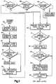
- Figure 4 is a state diagram that illustrates the preferred method of enhancing service signals transmitted by a modem to a data terminal equipment user, to include information such as the source of the signal received by the modem and a presentation string.
- Figure 5 is a block diagram that shows three examples of enhanced service signals.
- Figure 6 is a block diagram showing the structure of the logic design of the preferred method of introducing a connection delay parameter that delays transmission of data from the modem to the terminal equipment user for a predetermined time after transmission by the modem of a connection confirmation message.
- FIG. 1 shows the preferred system configuration for use of the present invention.
- a typical system consists of a DTE 10 , such as portable computer, a modem 11 suitable for use with a wireless communication network such as Mobitex Radio Network 12 , a gateway 13 , for communication between Mobitex 12 and an X.25 network 14 , and a remote computer system 15 connected to X.25 network 14 .
- gateway 13 may be connected directly to remote computer system 15 , since both are X.25 compatible.
- modem 11 is a Mobidem, but may be any radio based modem that is capable of transmitting digital information across a wireless data communication network such as Mobitex 12 .
- DTE 10 is physically connected to modem 11 by a standard RS-232 cable 16 , which is suitable for bi-directional transmission of serial data.
- Mobitex 12 is connected to gateway 13 by a leased line, and gateway 13 is connected to X.25 Network 14 by a synchronous modem (not shown).
- gateway 13 is a RIMGATE available from Research In Motion of Waterloo, Canada.
- the system configuration illustrated in Figure 1 allows the DTE user to communicate effectively with remote computer system 15 .
- Information is transmitted from DTE 10 to Mobidem 11 as an asynchronous stream of data.
- Mobidem 11 receives this data, processes it and assembles it into Mobitex data packets (MPAKs), which are suitable for transmission through Mobitex 12 .
- Mobitex 12 receives the MPAKs transmitted by Mobidem 11 and relays those MPAKs to gateway 13 .
- Gateway 13 disassembles the MPAKs and reassembles the data into X.25 data packets that can either be transmitted through X.25 network 14 to remote computer system 15 or, if there is a direct connection between the gateway 13 and the remote computer system 15 , transmitted directly to remote computer system 15 .
- remote computer system 15 can transmit information to DTE 10 .
- Remote computer system 15 transmits X.25 data packets to gateway 13 , where they are disassembled and reassembled into MPAKs that are transmitted through Mobitex 12 to Mobidem 11 .
- Mobidem 11 disassembles the MPAKs and transmits the data to DTE 10 as a serial asynchronous data stream.
- gateway 13 acts as an intermediate node between Mobitex 12 and X.25 Network 14 .
- a DTE user may communicate with another DTE user by designating that data packets be routed to another Mobidem (not shown). In this way a DTE user can communicate directly with another DTE user through Mobitex 12 .
- AT Modems have two basic states of operation; a command state and a data transfer state.
- the DTE user can send command signals to modem 11 to set various modem operating parameters and store these parameters in memory.
- the DTE user sets these parameters by sending control signals across RS-232 cable 16 to modem 11 .
- These parameters may be stored in a memory device, such as an electrically alterable ROM, so that the user's selected operating parameters are not lost if modem 11 is turned off and back on.
- a service signal is a simple message that informs the DTE user that the modem has changed state. For example, when a standard AT Modem receives a connection request, it generates a service signal that causes the DTE to display the message "RING". Any transmission routed though a wireless communication network such as Mobitex 12 , however, includes certain routing information and can be encoded with additional information that can be used to enhance service signals transmitted to the DTE for display.
- the user also has the ability to enable verbose message mode (#V1) and extended verbose message mode (#V2).
- #V1 and #V2 cause additional information to be included with the service signal displayed to the DTE user.
- #V1 causes the Mobitex Access Number (MAN) of the calling device to be displayed with the service signal and
- #V2 causes the MAN number and a presentation string to be displayed with the service signal.
- MAN Mobitex Access Number
- FIG. 2 is a general block diagram of modem 11 , which is suitable for use with a wireless communication network such as Mobitex 12 .
- modem 11 for use in accordance the this invention is a Mobidem and DTE 10 is physically connected to Modem 11 by a standard RS-232 cable 16 , which is suitable for bi-directional transmission of serial data.
- This connection to modem 11 is made through a standard RS-232 interface 20 .
- RS-232 interface 20 accepts control signals and serial data transmitted from DTE 10 and relays that information to microcomputer 22 through buffer 21 .
- Buffer 21 stores information received from RS-232 interface 20 until microcomputer 22 is ready to accept it.
- Buffer 21 also stores information received from microcomputer 22 , which is transmitted to DTE 10 through RS-232 interface 20 when DTE 10 is ready to accept it.
- Microcomputer 22 contains the logic circuitry and memory required to implement the invention. Microcomputer 22 takes serial data received from buffer 21 and assembles that data into MPAKs for transmission through Mobitex 12 . Microcomputer 22 also disassembles MPAKs received from Mobitex 12 and configures that data into a serial data stream for transmission to DTE 10 .
- Information that has been assembled into MPAKs for transmission through Mobitex 12 is first modulated by modulator/demodulator 23 and then forwarded to radio transceiver 24 . From radio transceiver 24 , information is transmitted to Mobitex 12 through antenna 25 . Transceiver 24 also receives modulated signals through antenna 25 that include information in MPAKs from Mobitex 12 . These signals are demodulated by modulator/demodulator 23 and forwarded to microcomputer 22 . As noted above, microcomputer 22 disassembles MPAKs received from Mobitex 12 and configures that data into a serial data stream for transmission to DTE 10 . Microcomputer 22 also examines these signals for validity and content.
- FIG. 3 is a detailed illustration of the various protocol layers involved in supporting an end-to-end connection between Mobidem 11 and gateway 13 or another Mobidem. These layers work together as defined by the International Standard's Committee (ISO's) paper on Open System Interconnect (OSI). Each protocol layer has its own distinct header that enables it to perform its specific protocol functions. The exact format of each protocol, the service definition between the different layers and the function of each protocol is set forth in a series of documents available from Ericsson Sweden and Eritel Sweden including:
- adjacent layers make use of lower layers for services.
- the application on both sides of the Mobitex connection makes use of the session interface to access a range of session services.
- these services include: Session Open (Accept) Connection, Session Close Connection and Session Send Data.
- the function of these services include opening a session, closing a session and sending data through a session.
- Each of these services is completely defined by the MCP/1 specifications referenced above.
- the Session layer makes use of the transport interface to access a range of transport services, including, Transport Open Connection, Transport Close Connection and Transport Send Data.
- transport services including, Transport Open Connection, Transport Close Connection and Transport Send Data.
- the function of these services is to open a transport connection, close a transport connection and send data through a transport connection.
- transport connection Each of these services is completely defined by the MTP/1 specifications referenced above.
- the transport layer interfaces with the network layer and makes use of the network layer for services.
- the object of the transport layer is to guarantee the delivery of data.
- the transport layer makes use of the Network layer for network services.
- the basic function of the Network layer is to build and interpret MPAKs.
- the radio protocol layers implement ROSI and GMSK, which perform the modulation/demodulation required to convert data into the RF format used by Mobitex.
- ROSI is a method used to place data into small packets for transmission.
- GMSK stands for Gauss Mean Shift Keying and is simply a modulation technique used for modulating FM data on a radio signal.
- Establishing and maintaining a connection between Mobidem 11 and gateway 13 through Mobitex 12 involves each of the protocols shown in Figure 3. For example, as data arrives into Mobidem 11 from Mobitex 12 , it is passed through Radio layers 30 to the to Network layer 21 . Data arrives at Network layer 31 in MPAKs, where is checked to make sure that data has arrived in the correct format and then passed to Transport layer 32 . The MTP/1-based Transport layer 32 looks at the MTP/1 message type, found in the first three bytes of the message, also called the message header, to determine how to process the MTP/1 message. Protocol messages exchanged between different Transport layers are called Transport Protocol Data Units (TPDUs) and follow the format documented in the MTP/1 specification referenced above.
- TPDUs Transport Protocol Data Units
- Transport layer 32 After Transport layer 32 has decoded the TPDU, it passes the message up to Session layer 33 as a session message. Protocol messages exchanged between different Session layers are called Session Protocol Data Units (SPDUs) and follow the format documented in the MCP/1 specification referenced above. Session layer 33 interfaces with Application 34 .
- SPDUs Session Protocol Data Units
- FIG. 4 is a state diagram that illustrates the preferred method of enhancing service signals transmitted by a modem to a DTE user.
- gateway 13 sends an MPAK through Mobitex 12 that includes a connection request.
- Each MPAK includes a source and destination Mobitex Access Number (MAN) that is used by Mobitex for routing and billing purposes.
- MAN Mobitex Access Number
- Mobidem 11 receives a valid MPAK, it takes out the MAN number and hands this information along with any data present in the MPAK to Transport layer 32 , functionally represented by block 42 .
- the transport layer interprets the TPDU, to determine how to process it. If the TPDU is a connection request (CR), Transport layer 32 opens a transport connection and marks it as 'opening' and passes the CR to Session layer 33 . If the TPDU is a connection confirmation (CC), Transport layer 32 looks for a transport connection that is in the 'opening' state, marks it as 'opened' and passes the CC message to Session layer 33 . If the TPDU is a disconnect request (DR) it looks for a transport connection that is in the 'opened' state or the 'opening' state, removes the connection from the list of open connections, and passes the DR up to Session layer 33 .
- CR connection request
- CC connection confirmation
- DR disconnect request
- Transport layer 32 also converts the MAN numbers received from Network layer 31 into Transport Service Access Points (TSAPs), which are also passed up to Session layer 33 .
- TSAP Transport Service Access Points
- a TSAP is simply the MAN numbers with a 4 bit identification code attached. defined in the MTP/1 specification.
- the message, TSAP and any other data received from Network layer 32 is passed up to the session layer as a Session SPDU, block 43 .
- Session layer 33 examines the SPDU received from Transport layer 32 to determine the content of the SPDU and to check to see if a presentation string is present, block 44 . If a presentation string is present, the session layer extracts the presentation string from the SPDU, block 45 . The SPDU from the transport layer should match the current state of the session layer. If the SPDU is a CR, the session layer 33 checks to see if a connection with the same TSAP exists and if not opens the connection. If the SPDU is a CC or a DR, the session layer scans its list of connections for a connection already open to the same TSAP.
- the session layer Once the session layer has performed its tests and verified the SPDU, it converts the TSAP to a Session Service Access Point (SSAP) as required by the MCP/1 specification referenced above.
- SSAP Session Service Access Point
- the SPDU, presentation string and SSAP are then passed to the Application 34 as a Session Request, block 46 .
- Application 34 After Application 34 receives the Session Request, it determines whether it is a valid request as illustrated by blocks 47-49 .
- the Session Request is a CR
- the application checks to ensure that a connection is not already opened or pending;
- the Session Request is a CC
- the application verifies that it has made a CR.
- the Session Request is a DR
- the application verifies that a full connection is currently open. When a match is reached, the application determines the type of service signal that will be transmitted to the DTE user, block 50 .
- the application Before the service signal is sent to the DTE user, the application checks to determine whether the user has selected verbose message mode and extended verbose message mode. If the setting #V1 is detected, block 51 , the MAN number of the calling device is included with the standard service signal, block 52 . Application 34 extracts the calling MAN number from the SSAP by deleting the four bit identification code and using the MAN number from the SSAP data structure that corresponds to the calling device. If the setting #V2 is detected, the presentation string is added to the service signal and the MAN number, block 53 . Finally the application sends the enhanced service signal to the DTE user over RS-232 interface, block 54 .
- FIG. 5 is a block diagram that shows three examples enhanced service signals.
- Example 1 is an illustration of gateway 13 accessing modem 11 , which is essentially the same as the example discussed in connection with Figure 4.
- the DTE user requested a connection to a given MAN using a standard AT Modem Dial command.
- a full connection sequence as defined by MTP/1 and MCP/1 is a two step process. It involves a CR followed by a CC. These are symmetrical messages and they contain same information as for the application is concerned. Therefore it is possible to include a presentation string on the CR and the CC messages that are exchanged between the session and application layers.
- a CC returns from the gateway.
- the standard service signal "Connect 9600" will be extended to include the MAN number of the gateway and a presentation string if provided by the gateway.
- the gateway has initiated a disconnect and included a disconnect string.
- a disconnect could occur if the remote computer system abruptly disconnected the DTE user, of the CR failed. If the DTE user has enabled extended verbose messages, the DTE user can see the disconnect string attached to the standard service signal "No Carrier".
- Figure 6 is a block diagram that illustrates the structure of the logic design of the preferred method of introducing a connection delay parameter that delays transmission of data from modem 11 to DTE 10 for a predetermined time after transmission by modem 11 of a connection confirmation signal.
- the logic conceptually begins at block 60 when a connection is established between modem 11 and remote computer system 15 .
- modem 11 receives a connection confirmation signal from remote computer system 15 it enters a connected state 60 and then proceeds to block 61 , where it generates a service signal that notifies DTE 10 that a connection has been established.
- modem 11 proceeds to block 62 , which recalls the value of the connection delay parameter selected by the user, and then to block 63 , which initiates a timer.
- Block 64 compares the value of the timer to the value of the connection delay parameter. When the value of the timer exceeds the value of the connection delay parameter, modem 11 drops down to block 65 and begins sending data to DTE 10 .
- This procedure provides a delay between transmission of a connection service signal and transmission of data by DCE 11 to allow DTE 10 sufficient time to make any internal adjustments that may be necessary to accept data from DCE 11 .
- the preferred embodiment also provides a mechanism to allow the DTE user to set the duration of the delay to accommodate various DTE equipment and configurations.
Landscapes
- Engineering & Computer Science (AREA)
- Computer Networks & Wireless Communication (AREA)
- Signal Processing (AREA)
- Communication Control (AREA)
- Computer And Data Communications (AREA)
- Mobile Radio Communication Systems (AREA)
- Telephonic Communication Services (AREA)
Abstract
Description
- This invention relates generally to the art of connecting data terminal equipment (DTE) users to remote computer systems (or hosts) through a wireless or radio wave data communication network. The invention disclosed may, however, be useful for other forms of data transmission and communication systems.
- Over the past several decades, various communication networks have evolved to meet the growing need for access to information. Among the more familiar types of systems used for communication are wire-based telephone communication systems that use physical wires or optical fiber links to connect users. Data transmission using wire-based telephone communication systems can be accomplished using existing AT Modem technology. An AT Modem is a standard data communication equipment (DCE) connection device used with telephone equipment for converting or modulating an asynchronous stream of data into a phone line carrier signal. The connection between an AT Modem and a DTE, such as a personal computer or a portable computer, is usually through an RS-232 interface. One of the principal disadvantages of a wire-based telephone communication network is that users are limited to specific locations where wired connections are available. Another disadvantage is that wire-based telephone communication networks usually require dedicated telephone lines, which can be expensive.
- Recently wireless data communication networks have emerged that enables information exchange by sending and receiving data through high frequency radio signals. Examples of such networks include the Mobitex Radio Network (Mobitex), which is operated by RAM Mobile Data, and Ardis, which is a joint venture of Motorola and IBM. Mobitex was developed in Sweden by Ericsson/Eritel and has been installed and is maintained in many other countries. For example, in Canada, Mobitex is operated by Roger's Cantel. Making efficient use of these wireless data communication networks to connect DTE users to remote computer systems is one of the objects of this invention.
- Electronic data communication is organized into networks that have established protocols and specifications. Communication between computers takes place over a connection that is established using a common protocol. A data communication network generally refers to a collection or grouping of computers organized for co-operative communication of data. Once a connection is established, there are a number of data transfer methods used by various data communication networks. Both Mobitex and Ardis use packet switched data transfer methods, which aggregate data into blocks called packets before it is transmitted.
- Ericsson also manufactures a device called a Mobidem, which is a radio based modem that is capable of transmitting digital information across the Mobitex data communication network. A Mobidem essentially provides an interface between a DTE user and Mobitex. Unfortunately, effective communication between a DTE user and a remote computer system across a wireless communication network, such as Mobitex, requires significant enhancements to support the standard AT Modem protocol. An object of this invention is to provide an enhanced user interface to a wireless data communication network such as Mobitex that is compatible with standard AT Modem technology.
- A standard AT compatible modem is capable of sending a number of service signals to its DTE user that indicate changes in the status of the modem. For example, if the user makes a call to a remote computer system, several possible events may occur that result in associated service signals:
- if the modem is disconnected, the message "No Carrier" will be displayed;
- if a connection is made, the messaqe "Connect 2400" will be displayed; and
- if the call is made and the remote computer does not answer, "Busy" or "No Answer" will be displayed.
- These messages can handle all of the events that can occur in the operation of a land-line modem (i.e. one that uses telephone lines).
- The user of the modem has the option of setting various AT Modem parameters that affect whether service signals are transmitted by the modem to the DTE and the form in which they are transmitted. If the user enables the modem to transmit text service signals, the messages noted above will be transmitted to the DTE for display. If the user enables the modem to transmit numeric messages, the modem will transmit a numeric code to the DTE that corresponds to the event that occurred. If user does not enable the modem to transmit service signals, service signals will not be transmitted to the DTE.
- Since any transmission from a remote computer to a DTE user through a wireless communication network such as Mobitex can be encoded with additional information, use of an AT compatible modem in conjunction with Mobitex adds a new dimension of information that can be displayed when an event occurs. An object of this invention is to enhance an AT compatible modem to transmit service signals that include information such as the identity of the caller and a presentation string.
- All AT Modems have two basic states of operation; a command state and a data transfer state. In the command state, the DTE user can send command signals to the modem and change the modem's operating parameters. At start-up, an AT Modem is in the command state. When a connection is established, an AT Modem automatically shifts to the data transfer state. Because data received by a radio-based modem such as a Mobidem is received in packets, under certain conditions data will be waiting to be transmitted to the user immediately after the modem enters the data transfer state. Unfortunately, many DTE user applications will fail if the modem begins transmitting data to the user immediately after the modem transmits an entering-data-transfer-state signal.
- In WO 91/07044, there is disclosed a system according to the preamble of
claim 1 and 18, respectively, which can simultaneously transmit both voice and data over either a landline telephone connection or a cellular connection. The essence of this known system is a modem which can transmit data over either (1) traditional land-based telephone wires or (2) cellular telephone frequencies. In addition, this document discloses what is now commonly known as MNP (Modified Networking Protocol). This protocol is a packet-based technique which divides a data stream into individual packets, each packet including a 16-bit CRC (Cyclic Redundancy Check) for accuracy. This type of protocol is required for a cellular type modem in order to ensure error-free data transmission, primarily due to the noisy nature of the cellular transmission medium. - In US-A-4,776,005, there is disclosed a system which is essentially an extension of the well known telephone "caller-ID" function. In "caller-ID", a phone is equipped with additional circuitry which enables it to extract the phone number of an incoming call and display the calling parties number to a user of the phone. In US-A-4,776,005 it is suggested to extend this well known telephony technique by outputting the extracted calling number and the called number in a serial data-stream to a PC, which contains a database of information indexed by the calling and called numbers. Using this index, the database displays information to the user, such as who is the person calling, whom are they calling, whether the called person is available, and so on.
- The aforementioned objects of the present invention are solved by the advantageous measures indicated in the characterizing part of
claim 1 and 18, respectively. - Advantageous further developments of the invention are the subject-matter of the subclaims.
- The novel and useful features of the invention are set forth in the claims. The invention itself, however, as well as specific features and advantages of the invention may be best understood by reference to the detailed description that follows, when read in conjunction with the accompanying drawings.
- Figure 1 is a block diagram that illustrates a typical connection between a DTE user and a remote computer system through a wireless data communication network.
- Figure 2 is a general block diagram of the basic hardware components of a modem suitable for use with a wireless communication network.
- Figure 3 is a block diagram showing the protocol layers involved in establishing and maintaining a connection between a DTE user and a remote computer system through a wireless communication network.
- Figure 4 is a state diagram that illustrates the preferred method of enhancing service signals transmitted by a modem to a data terminal equipment user, to include information such as the source of the signal received by the modem and a presentation string.
- Figure 5 is a block diagram that shows three examples of enhanced service signals.
- Figure 6 is a block diagram showing the structure of the logic design of the preferred method of introducing a connection delay parameter that delays transmission of data from the modem to the terminal equipment user for a predetermined time after transmission by the modem of a connection confirmation message.
- Figure 1 shows the preferred system configuration for use of the present invention. A typical system consists of a
DTE 10, such as portable computer, amodem 11 suitable for use with a wireless communication network such as Mobitex Radio Network 12, agateway 13, for communication between Mobitex 12 and an X.25 network 14, and aremote computer system 15 connected to X.25 network 14. Alternatively,gateway 13 may be connected directly toremote computer system 15, since both are X.25 compatible. In thepreferred embodiment modem 11 is a Mobidem, but may be any radio based modem that is capable of transmitting digital information across a wireless data communication network such asMobitex 12.DTE 10 is physically connected tomodem 11 by a standard RS-232cable 16, which is suitable for bi-directional transmission of serial data.Mobitex 12 is connected togateway 13 by a leased line, andgateway 13 is connected to X.25 Network 14 by a synchronous modem (not shown). Also, in the preferred embodiment,gateway 13 is a RIMGATE available from Research In Motion of Waterloo, Canada. - The system configuration illustrated in Figure 1 allows the DTE user to communicate effectively with
remote computer system 15. Information is transmitted fromDTE 10 to Mobidem 11 as an asynchronous stream of data.Mobidem 11 receives this data, processes it and assembles it into Mobitex data packets (MPAKs), which are suitable for transmission throughMobitex 12.Mobitex 12 receives the MPAKs transmitted byMobidem 11 and relays those MPAKs togateway 13.Gateway 13 disassembles the MPAKs and reassembles the data into X.25 data packets that can either be transmitted through X.25 network 14 toremote computer system 15 or, if there is a direct connection between thegateway 13 and theremote computer system 15, transmitted directly toremote computer system 15. - In a similar fashion,
remote computer system 15 can transmit information toDTE 10.Remote computer system 15 transmits X.25 data packets togateway 13, where they are disassembled and reassembled into MPAKs that are transmitted throughMobitex 12 toMobidem 11.Mobidem 11 disassembles the MPAKs and transmits the data toDTE 10 as a serial asynchronous data stream. - In Figure 1,
gateway 13 acts as an intermediate node betweenMobitex 12 and X.25 Network 14. Instead of connecting to a remote computer system, a DTE user may communicate with another DTE user by designating that data packets be routed to another Mobidem (not shown). In this way a DTE user can communicate directly with another DTE user throughMobitex 12. - AT Modems have two basic states of operation; a command state and a data transfer state. In the command state, the DTE user can send command signals to
modem 11 to set various modem operating parameters and store these parameters in memory. The DTE user sets these parameters by sending control signals across RS-232cable 16 tomodem 11. These parameters may be stored in a memory device, such as an electrically alterable ROM, so that the user's selected operating parameters are not lost ifmodem 11 is turned off and back on. - One of the operating parameters that can be set by the user of a conventional AT modem is whether service signals are transmitted to the DTE. A service signal is a simple message that informs the DTE user that the modem has changed state. For example, when a standard AT Modem receives a connection request, it generates a service signal that causes the DTE to display the message "RING". Any transmission routed though a wireless communication network such as
Mobitex 12, however, includes certain routing information and can be encoded with additional information that can be used to enhance service signals transmitted to the DTE for display. In accordance with the present invention, the user also has the ability to enable verbose message mode (#V1) and extended verbose message mode (#V2). #V1 and #V2 cause additional information to be included with the service signal displayed to the DTE user. #V1 causes the Mobitex Access Number (MAN) of the calling device to be displayed with the service signal and #V2 causes the MAN number and a presentation string to be displayed with the service signal. - Figure 2 is a general block diagram of
modem 11, which is suitable for use with a wireless communication network such asMobitex 12. As noted above, in thepreferred modem 11 for use in accordance the this invention is a Mobidem andDTE 10 is physically connected toModem 11 by a standard RS-232cable 16, which is suitable for bi-directional transmission of serial data. This connection tomodem 11 is made through a standard RS-232interface 20. RS-232interface 20 accepts control signals and serial data transmitted fromDTE 10 and relays that information tomicrocomputer 22 throughbuffer 21.Buffer 21 stores information received from RS-232interface 20 untilmicrocomputer 22 is ready to accept it.Buffer 21 also stores information received frommicrocomputer 22, which is transmitted toDTE 10 through RS-232interface 20 whenDTE 10 is ready to accept it.Microcomputer 22 contains the logic circuitry and memory required to implement the invention.Microcomputer 22 takes serial data received frombuffer 21 and assembles that data into MPAKs for transmission throughMobitex 12.Microcomputer 22 also disassembles MPAKs received fromMobitex 12 and configures that data into a serial data stream for transmission toDTE 10. - Information that has been assembled into MPAKs for transmission through
Mobitex 12 is first modulated by modulator/demodulator 23 and then forwarded toradio transceiver 24. Fromradio transceiver 24, information is transmitted toMobitex 12 throughantenna 25.Transceiver 24 also receives modulated signals throughantenna 25 that include information in MPAKs fromMobitex 12. These signals are demodulated by modulator/demodulator 23 and forwarded tomicrocomputer 22. As noted above,microcomputer 22 disassembles MPAKs received fromMobitex 12 and configures that data into a serial data stream for transmission toDTE 10.Microcomputer 22 also examines these signals for validity and content. - Operation of
Mobidem 11 in connection withgateway 13, or in connection with another Mobidem involves several protocol layers. Figure 3 is a detailed illustration of the various protocol layers involved in supporting an end-to-end connection betweenMobidem 11 andgateway 13 or another Mobidem. These layers work together as defined by the International Standard's Committee (ISO's) paper on Open System Interconnect (OSI). Each protocol layer has its own distinct header that enables it to perform its specific protocol functions. The exact format of each protocol, the service definition between the different layers and the function of each protocol is set forth in a series of documents available from Ericsson Sweden and Eritel Sweden including: - a. Mobitex Terminal Specification
001 53-03/L2BA 703 1001
Section: Mobitex Network Layers for Terminals
S/1056-A-296 S171/0 Ue
Eritel AB, Sweden - b. Mobitex Transport Protocol, Release B (MTP/1)
Y/KL-91:754
1/115517-CALA 88215
By: Anders Olsson and Eddie Johansson
Ericsson Mobile Communications AB - c. Mobitex Transport Service Definition
AUR-92:760
By: Anders Olsson
Ericsson Mobile Communications AB - d. MCP/1 Mobitex Compression Protocol
ECS Y/G-93:0242
By: Jack De Winter
Research In Motion, Waterloo, Canada and
Ericsson AB, Sweden - e. MCP/1 Mobitex Compression Service
Definition
ECS Y/G-93:0241
By: Jack De Winter
Research In Motion, Waterloo, Canada and
Ericsson AB, Sweden - As shown in Figure 3, adjacent layers make use of lower layers for services. The application on both sides of the Mobitex connection makes use of the session interface to access a range of session services. Examples of these services include: Session Open (Accept) Connection, Session Close Connection and Session Send Data. The function of these services include opening a session, closing a session and sending data through a session. Each of these services is completely defined by the MCP/1 specifications referenced above.
- The Session layer makes use of the transport interface to access a range of transport services, including, Transport Open Connection, Transport Close Connection and Transport Send Data. The function of these services is to open a transport connection, close a transport connection and send data through a transport connection. Each of these services is completely defined by the MTP/1 specifications referenced above. The transport layer interfaces with the network layer and makes use of the network layer for services. The object of the transport layer is to guarantee the delivery of data.
- The transport layer makes use of the Network layer for network services. The basic function of the Network layer is to build and interpret MPAKs. The radio protocol layers implement ROSI and GMSK, which perform the modulation/demodulation required to convert data into the RF format used by Mobitex. ROSI is a method used to place data into small packets for transmission. GMSK stands for Gauss Mean Shift Keying and is simply a modulation technique used for modulating FM data on a radio signal.
- Establishing and maintaining a connection between
Mobidem 11 andgateway 13 throughMobitex 12 involves each of the protocols shown in Figure 3. For example, as data arrives intoMobidem 11 fromMobitex 12, it is passed through Radio layers 30 to the toNetwork layer 21. Data arrives at Network layer 31 in MPAKs, where is checked to make sure that data has arrived in the correct format and then passed to Transportlayer 32. The MTP/1-basedTransport layer 32 looks at the MTP/1 message type, found in the first three bytes of the message, also called the message header, to determine how to process the MTP/1 message. Protocol messages exchanged between different Transport layers are called Transport Protocol Data Units (TPDUs) and follow the format documented in the MTP/1 specification referenced above. AfterTransport layer 32 has decoded the TPDU, it passes the message up toSession layer 33 as a session message. Protocol messages exchanged between different Session layers are called Session Protocol Data Units (SPDUs) and follow the format documented in the MCP/1 specification referenced above.Session layer 33 interfaces withApplication 34. - Figure 4 is a state diagram that illustrates the preferred method of enhancing service signals transmitted by a modem to a DTE user. For example, to establish a connection with
Mobidem 11,gateway 13 sends an MPAK throughMobitex 12 that includes a connection request. Each MPAK includes a source and destination Mobitex Access Number (MAN) that is used by Mobitex for routing and billing purposes. As noted above, as data arrives intoMobidem 11 fromMobitex 12, it is passed through the Radio layers to the to Network layer 31, functionally represented byblock 41. At network layer, whenMobidem 11 receives a valid MPAK, it takes out the MAN number and hands this information along with any data present in the MPAK toTransport layer 32, functionally represented byblock 42. The transport layer, interprets the TPDU, to determine how to process it. If the TPDU is a connection request (CR),Transport layer 32 opens a transport connection and marks it as 'opening' and passes the CR toSession layer 33. If the TPDU is a connection confirmation (CC),Transport layer 32 looks for a transport connection that is in the 'opening' state, marks it as 'opened' and passes the CC message toSession layer 33. If the TPDU is a disconnect request (DR) it looks for a transport connection that is in the 'opened' state or the 'opening' state, removes the connection from the list of open connections, and passes the DR up toSession layer 33. (The MTP/1 specification referenced above lists other messages that may be encountered by the transport layer.)Transport layer 32 also converts the MAN numbers received from Network layer 31 into Transport Service Access Points (TSAPs), which are also passed up toSession layer 33. A TSAP is simply the MAN numbers with a 4 bit identification code attached. defined in the MTP/1 specification. The message, TSAP and any other data received fromNetwork layer 32 is passed up to the session layer as a Session SPDU, block 43. -
Session layer 33, examines the SPDU received fromTransport layer 32 to determine the content of the SPDU and to check to see if a presentation string is present, block 44. If a presentation string is present, the session layer extracts the presentation string from the SPDU, block 45. The SPDU from the transport layer should match the current state of the session layer. If the SPDU is a CR, thesession layer 33 checks to see if a connection with the same TSAP exists and if not opens the connection. If the SPDU is a CC or a DR, the session layer scans its list of connections for a connection already open to the same TSAP. Once the session layer has performed its tests and verified the SPDU, it converts the TSAP to a Session Service Access Point (SSAP) as required by the MCP/1 specification referenced above. The SPDU, presentation string and SSAP are then passed to theApplication 34 as a Session Request, block 46. - After
Application 34 receives the Session Request, it determines whether it is a valid request as illustrated by blocks 47-49. Atblock 47, if the Session Request is a CR, the application checks to ensure that a connection is not already opened or pending; Atblock 48, if the Session Request is a CC, the application verifies that it has made a CR. Atblock 49, if the Session Request is a DR, the application verifies that a full connection is currently open. When a match is reached, the application determines the type of service signal that will be transmitted to the DTE user, block 50. - Before the service signal is sent to the DTE user, the application checks to determine whether the user has selected verbose message mode and extended verbose message mode. If the setting #V1 is detected, block 51, the MAN number of the calling device is included with the standard service signal, block 52.
Application 34 extracts the calling MAN number from the SSAP by deleting the four bit identification code and using the MAN number from the SSAP data structure that corresponds to the calling device. If the setting #V2 is detected, the presentation string is added to the service signal and the MAN number, block 53. Finally the application sends the enhanced service signal to the DTE user over RS-232 interface, block 54. - Figure 5 is a block diagram that shows three examples enhanced service signals. Example 1 is an illustration of
gateway 13 accessingmodem 11, which is essentially the same as the example discussed in connection with Figure 4. - In example 2, the DTE user requested a connection to a given MAN using a standard AT Modem Dial command. As noted above, a full connection sequence, as defined by MTP/1 and MCP/1 is a two step process. It involves a CR followed by a CC. These are symmetrical messages and they contain same information as for the application is concerned. Therefore it is possible to include a presentation string on the CR and the CC messages that are exchanged between the session and application layers. When a connection is accepted, a CC returns from the gateway. In the example, if the DTE user has enabled extended verbose messages, the standard service signal "
Connect 9600" will be extended to include the MAN number of the gateway and a presentation string if provided by the gateway. - In example 3, the gateway has initiated a disconnect and included a disconnect string. A disconnect could occur if the remote computer system abruptly disconnected the DTE user, of the CR failed. If the DTE user has enabled extended verbose messages, the DTE user can see the disconnect string attached to the standard service signal "No Carrier".
- Figure 6 is a block diagram that illustrates the structure of the logic design of the preferred method of introducing a connection delay parameter that delays transmission of data from
modem 11 toDTE 10 for a predetermined time after transmission bymodem 11 of a connection confirmation signal. - The logic conceptually begins at
block 60 when a connection is established betweenmodem 11 andremote computer system 15. Whenmodem 11 receives a connection confirmation signal fromremote computer system 15 it enters aconnected state 60 and then proceeds to block 61, where it generates a service signal that notifiesDTE 10 that a connection has been established. After sending the connection service signal,modem 11 proceeds to block 62, which recalls the value of the connection delay parameter selected by the user, and then to block 63, which initiates a timer.Block 64 compares the value of the timer to the value of the connection delay parameter. When the value of the timer exceeds the value of the connection delay parameter,modem 11 drops down to block 65 and begins sending data toDTE 10. This procedure provides a delay between transmission of a connection service signal and transmission of data byDCE 11 to allowDTE 10 sufficient time to make any internal adjustments that may be necessary to accept data fromDCE 11. The preferred embodiment also provides a mechanism to allow the DTE user to set the duration of the delay to accommodate various DTE equipment and configurations.
Claims (31)
- Method of enhancing service signals transmitted by a data communication equipment (11) to a data terminal equipment (10) user, in which a modulated signal is received by said data communication equipment (11);
characterized by the steps of:[a] enabling one or more enhanced service signals at said data communication equipment (11), wherein one of said enhanced service signals indicates the source (15) of the received modulated signal;[b] processing the modulated signal received by said data communication equipment (11) to determine the source of the modulated signal, and generating the enhanced service signal that indicates the source (15) of the received modulated signal; and[c] transmitting the processed modulated signal and the one or more enhanced service signals from said data communication equipment (11) to said data terminal equipment (10). - Method according to claim 1, characterized by the step of displaying at said data terminal equipment (10) the enhanced service signal that indicates the source (15) of the modulated signal received by said data communication equipment (11).
- Method according to claim 1 or 2, characterized in that the modulated signal received by said data communication equipment (11) is transmitted from a communication network (12).
- Method according to claim 3, characterized in that said communication network (12) is a wireless RF communication network.
- Method according to one of claims 1 through 4, characterized in that the processing step further includes determining whether the received modulated signal includes message data transmitted by the source (15) of the modulated signal, and if so, including the message data in the enhanced service signal that indicates the source (15) of the received modulated signal generated by the data communication equipment (11).
- Method according to claim 5, characterized by the step of displaying at the data terminal equipment (10) the message data included in the enhanced service signal that indicates the source (15) of the received modulated signal generated by said data communication equipment (11).
- Method according to ciaim 5, characterized in that the enabling step further includes selecting whether each of the one or more enhanced service signals are to be transmitted to said data terminal equipment (10) from said data communication equipment (11).
- Method according to claim 7, characterized in that the data terminal equipment user selects whether each of the one or more enhanced service signals are to be transmitted to said data terminal equipment (10) from said data communication equipment (11).
- Method according to one of claims 1 through 8, characterized in that the processing step further includes the steps of:demodulating the received modulated signal into one or more data packets; andextracting from the one or more data packets information which indicates the source (15) of the received modulated signal.
- Method according to claim 9, characterized in that the processing step further includes the step of configuring the demodulated data packet and the one or more enhanced service signals into a serial data stream.
- Method according to claim 10, characterized by the step of transmitting the serial data stream from said data communication equipment (11) to said data terminal equipment (10).
- Method according to claim 9, characterized by the steps of:transmitting a connection service signal to said data terminal equipment (10) indicating that said data communication equipment (11) has received one or more data packets;storing the one or more received data packets at said data communication equipment (11) until a predetermined period of time has expired; anddelaying for the predetermined time after transmitting the connection service signal before transmitting the one or more data packets from said data communication equipment (11) to said data terminal equipment (10), thereby preventing said data terminal equipment (10) from failing to respond to said data communication equipment (11).
- Method according to claim 12, characterized in that said predetermined time is reconfigurable by the data terminal equipment user.
- Method according to one of claims 1 through 13, characterized in that said data communication equipment is a modem (11).
- Method according to claim 8, characterized in that the data terminal equipment user selects whether each of the one or more enhanced service signals are to be transmitted to said data terminal equipment (10) from said data communication equipment (11) by transmitting a signal from said data terminal equipment (10) to said data communication equipment (11) which alters the operating parameters of said data communication equipment (11).
- Method according to one of claims 1 through 15, characterized in that the source of the received modulated signal is a remote computer system (15).
- Method according to claim 16, characterized in that said remote computer system (15) is connected to said data communication equipment (11) through a gateway system (13).
- Data communication equipment (11) for receiving data from a communication network (12) and for transmitting the data to a data terminal equipment (10) user, said data communication equipment (11) including a receiver (24) for receiving data from said communication network (12), wherein said data includes one or more data packets, a microcomputer (22) for disassembling the one or more data packets, and a transmitter (20) coupled to said microcomputer (22) for transmitting the one or more disassembled data packets to said data terminal equipment (11),
characterized in that[a] said microcomputer (22) is adapted to process the data packets to determine the source (15) of the data received from said communication network (12) and to generate one or more enhanced service signals, wherein one of said enhanced service signals indicates the source (15) of the data received from said communication network (12);[b] wherein said transmitter (20) further transmits the one or more enhanced service signals to said data terminal equipment (11). - Data communication equipment (11) according to claim 18, characterized in that said microcomputer is further configuring the one or more data packets and the one or more enhanced service signals into a serial data stream.
- Data communication equipment (11) according to claim 18 or 19, characterized by a memory for storing operating parameters of said data communication equipment (11).
- Data communication equipment (11) according to one of claims 18 through 20, characterized in that said transmitter (20) includes a serial data interface (20) for transmitting the serial data stream to said data terminal equipment (11).
- Data communication equipment (11) according to claim 18, characterized in that the data received from said communication network (12) is modulated, and said data communication equipment (11) further includes a demodulator (23) coupled between said receiver (24) and said microcomputer (22) for demodulating the modulated data received from said communication network (12).
- Data communication equipment (11) according to one of claims 18 through 22, characterized in that said communication network (12) is a wireless RF communication network.
- Data communication equipment (11) according to one of claims 18 through 23, characterized in that said microcomputer (22) is further processing the one or more data packets to determine whether any message data transmitted by the source (15) of the data received from said communication network (12) is present, and if so, is including the message data in the one or more enhanced service signals generated by said microcomputer (22).
- Data communication equipment (11) according to claim 20, characterized in that the processing, generating and configuring functions performed by said microcomputer (22) are enabled by the operating parameters stored in said memory of the data communication equipment.
- Data communication equipment (11) according to claim 25, characterized in that the operating parameters are set by the data terminal equipment user.
- Data communication equipment (11) according to one of claims 18 through 26, characterized in that said data communication equipment is a modem (11).
- Data communication equipment (11) according to claim 21, characterized in that said microcomputer (22) is further generating a connection service signal that indicates that said data communication equipment (11) has received data from said communication network (12).
- Data communication equipment (11) according to claim 28, characterized by a timer for delaying the transmission of the serial data stream to said data terminal equipment (10) for a predetermined period of time after said data communication equipment (11) generates the connection service signal.
- Data communication equipment (11) according to claim 29, characterized by a buffer (21) for storing the configured serial data stream until the predetermined period of time has expired.
- Data communication equipment (11) according to claim 29, characterized in that the predetermined period of time is an operating parameter of said data communication equipment (11) which is stored in said memory.
Applications Claiming Priority (3)
| Application Number | Priority Date | Filing Date | Title |
|---|---|---|---|
| US11487393A | 1993-08-31 | 1993-08-31 | |
| US114873 | 1993-08-31 | ||
| PCT/CA1994/000471 WO1995006997A1 (en) | 1993-08-31 | 1994-08-29 | Computer system for use with a wireless data communication network |
Publications (2)
| Publication Number | Publication Date |
|---|---|
| EP0715794A1 EP0715794A1 (en) | 1996-06-12 |
| EP0715794B1 true EP0715794B1 (en) | 1997-11-19 |
Family
ID=22357922
Family Applications (1)
| Application Number | Title | Priority Date | Filing Date |
|---|---|---|---|
| EP94925312A Expired - Lifetime EP0715794B1 (en) | 1993-08-31 | 1994-08-29 | Computer system for use with a wireless data communication network |
Country Status (6)
| Country | Link |
|---|---|
| US (2) | US5657345A (en) |
| EP (1) | EP0715794B1 (en) |
| JP (1) | JPH09500251A (en) |
| CA (1) | CA2170628C (en) |
| DE (1) | DE69406938T2 (en) |
| WO (1) | WO1995006997A1 (en) |
Families Citing this family (41)
| Publication number | Priority date | Publication date | Assignee | Title |
|---|---|---|---|---|
| CA2170628C (en) * | 1993-08-31 | 1999-08-17 | Mihal Lazaridis | Computer system for use with a wireless data communication network |
| FI98028C (en) * | 1995-05-03 | 1997-03-25 | Nokia Mobile Phones Ltd | data adapter |
| US7006261B1 (en) | 1995-06-14 | 2006-02-28 | Panasonic Communications Co., Ltd. | Modulator and demodulator (MODEM) |
| JP2978433B2 (en) * | 1995-06-14 | 1999-11-15 | 松下電送システム株式会社 | Modulation / demodulation device, communication device and facsimile device |
| US5960035A (en) * | 1995-09-29 | 1999-09-28 | Motorola Inc. | Method and apparatus for load balancing for a processor operated data communications device |
| US7035914B1 (en) * | 1996-01-26 | 2006-04-25 | Simpleair Holdings, Inc. | System and method for transmission of data |
| US5940383A (en) * | 1996-01-29 | 1999-08-17 | Qualcomm Incorporated | Automatic data service selection |
| US5764235A (en) * | 1996-03-25 | 1998-06-09 | Insight Development Corporation | Computer implemented method and system for transmitting graphical images from server to client at user selectable resolution |
| JP3581218B2 (en) * | 1996-07-03 | 2004-10-27 | 株式会社東芝 | Mobile communication terminal device and its mobile phone and data terminal device |
| US6272333B1 (en) * | 1998-06-12 | 2001-08-07 | Motorola, Inc. | Method and apparatus in a wireless communication system for controlling a delivery of data |
| US6489950B1 (en) | 1998-06-26 | 2002-12-03 | Research In Motion Limited | Hand-held electronic device with auxiliary input device |
| US6278442B1 (en) | 1998-06-26 | 2001-08-21 | Research In Motion Limited | Hand-held electronic device with a keyboard optimized for use with the thumbs |
| US7705828B2 (en) | 1998-06-26 | 2010-04-27 | Research In Motion Limited | Dual-mode mobile communication device |
| US6304746B1 (en) | 1998-11-17 | 2001-10-16 | Aether Systems, Inc. | Method and system for providing formatted information via a two-way communications system |
| US7689696B2 (en) * | 2000-01-31 | 2010-03-30 | Telecommunication Systems, Inc. | System and method for re-directing requests from browsers for communications over non-IP based networks |
| US7003571B1 (en) * | 2000-01-31 | 2006-02-21 | Telecommunication Systems Corporation Of Maryland | System and method for re-directing requests from browsers for communication over non-IP based networks |
| US8090856B1 (en) * | 2000-01-31 | 2012-01-03 | Telecommunication Systems, Inc. | Intelligent messaging network server interconnection |
| US7356570B1 (en) | 2000-08-29 | 2008-04-08 | Raja Tuli | Portable high speed communication device |
| US6633314B1 (en) | 2000-02-02 | 2003-10-14 | Raja Tuli | Portable high speed internet device integrating cellular telephone and palm top computer |
| US7023572B2 (en) * | 2000-02-02 | 2006-04-04 | Raja Singh Tuli | Portable high speed internet access device |
| US7289244B2 (en) | 2000-02-02 | 2007-10-30 | Raja Singh Tuli | Portable high speed internet access device |
| US20020115477A1 (en) * | 2001-02-13 | 2002-08-22 | Raja Singh | Portable high speed internet access device with scrolling |
| US7068381B1 (en) | 2000-02-02 | 2006-06-27 | Raja Tuli | Portable high speed internet access device |
| US20020030843A1 (en) * | 2000-02-02 | 2002-03-14 | Tuli Raja Singh | Portable high speed internet access device |
| US6941382B1 (en) | 2000-02-07 | 2005-09-06 | Raja Tuli | Portable high speed internet or desktop device |
| US6874009B1 (en) | 2000-02-16 | 2005-03-29 | Raja Tuli | Portable high speed internet device with user fees |
| US6560604B1 (en) | 2000-03-10 | 2003-05-06 | Aether Systems, Inc. | System, method, and apparatus for automatically and dynamically updating options, features, and/or services available to a client device |
| US7546141B2 (en) * | 2000-05-23 | 2009-06-09 | Robert Leon | Hybrid communication system and method |
| US6680923B1 (en) * | 2000-05-23 | 2004-01-20 | Calypso Wireless, Inc. | Communication system and method |
| US20020049076A1 (en) * | 2000-06-23 | 2002-04-25 | Jones Charles K. | Wide-area-network wireless modem with embedded communication protocol |
| US6842777B1 (en) | 2000-10-03 | 2005-01-11 | Raja Singh Tuli | Methods and apparatuses for simultaneous access by multiple remote devices |
| US7191211B2 (en) * | 2000-10-03 | 2007-03-13 | Raja Tuli | Portable high speed internet access device priority protocol |
| US6915327B1 (en) | 2000-10-30 | 2005-07-05 | Raja Singh Tuli | Portable high speed communication device peripheral connectivity |
| US6928461B2 (en) | 2001-01-24 | 2005-08-09 | Raja Singh Tuli | Portable high speed internet access device with encryption |
| US7113490B2 (en) * | 2001-12-17 | 2006-09-26 | Toshiba Tec Kabushiki Kaisha | Communication sequence, data circuit-terminating equipment, data terminal equipment, and storage medium storing communication control program |
| US20040078601A1 (en) * | 2002-08-02 | 2004-04-22 | Chris Tengwall | System and method for operating a wireless device network |
| US8176428B2 (en) | 2002-12-03 | 2012-05-08 | Datawind Net Access Corporation | Portable internet access device back page cache |
| US6885978B2 (en) * | 2003-03-19 | 2005-04-26 | Cisco Technology, Inc. | Auto-determination of DTE/DCE connection |
| CN1953406B (en) * | 2005-10-19 | 2011-06-01 | 株式会社Ntt都科摩 | Method for accessing hybrid network, gateway device, wireless terminal and communication system |
| JP2011530842A (en) * | 2008-07-11 | 2011-12-22 | マーベル ワールド トレード リミテッド | Service discovery method |
| JP5464890B2 (en) * | 2009-04-09 | 2014-04-09 | 株式会社日立国際電気 | Wireless communication device |
Family Cites Families (20)
| Publication number | Priority date | Publication date | Assignee | Title |
|---|---|---|---|---|
| US34034A (en) * | 1861-12-24 | Improvement in bee-hives | ||
| US3869577A (en) * | 1972-04-24 | 1975-03-04 | Gen Datacomm Ind Inc | Method and apparatus for control signaling in fdm system |
| NO132123C (en) * | 1973-04-13 | 1975-09-17 | Standard Tel Kabelfab As | |
| US4375103A (en) * | 1980-09-17 | 1983-02-22 | International Business Machines Corp. | Method and apparatus of signalling request to send clear to send delay |
| USRE34034E (en) * | 1985-10-11 | 1992-08-18 | Spectrum Information Technologies, Inc. | Cellular telephone data communication system and method |
| US4776005A (en) * | 1987-07-23 | 1988-10-04 | Affiliated Telephone, Inc. | Computer based information system for character display phone network |
| US4852122A (en) * | 1987-08-31 | 1989-07-25 | Universal Data Systems, Inc. | Modem suited for wireless communication channel use |
| JPH01175354A (en) * | 1987-12-28 | 1989-07-11 | Canon Inc | facsimile machine |
| US4991197A (en) * | 1988-09-01 | 1991-02-05 | Intelligence Technology Corporation | Method and apparatus for controlling transmission of voice and data signals |
| EP0450062A4 (en) * | 1989-10-31 | 1992-09-23 | Intelligence Technology Corporation | Data and voice transmission over a cellular telephone system |
| US5050205A (en) * | 1990-10-25 | 1991-09-17 | Communication Devices, Inc. | Dial line monitor and control unit |
| US5144651A (en) * | 1990-11-19 | 1992-09-01 | Exxon Research And Engineering Company | Reduced time remote access method and system |
| FI90172C (en) * | 1990-11-26 | 1993-12-27 | Nokia Mobile Phones Ltd | Device for connecting a computer to a separate analog telephone |
| US5241565A (en) * | 1991-06-25 | 1993-08-31 | Microcom Systems, Inc. | Method and apparatus for effecting efficient transmission of data |
| US5396536A (en) * | 1992-06-23 | 1995-03-07 | At&T Corp. | Automatic processing of calls with different communication modes in a telecommunications system |
| US5450438A (en) * | 1993-07-26 | 1995-09-12 | At&T Corp. | Fallback method to 1200 bits per second for use in mobile radio |
| CA2170628C (en) * | 1993-08-31 | 1999-08-17 | Mihal Lazaridis | Computer system for use with a wireless data communication network |
| CA2129418A1 (en) * | 1993-10-04 | 1995-04-05 | Mahendra Patel | Data-driven autorating for use in data communications |
| US5450530A (en) * | 1993-11-03 | 1995-09-12 | Rockwell International Corporation | High speed receiver/transmitter interface |
| US5515385A (en) * | 1994-03-09 | 1996-05-07 | Motorola, Inc. | Device and method for limiting delay by substantial elimination of duplicate synchronous data frames in a communication system |
-
1994
- 1994-08-29 CA CA002170628A patent/CA2170628C/en not_active Expired - Lifetime
- 1994-08-29 EP EP94925312A patent/EP0715794B1/en not_active Expired - Lifetime
- 1994-08-29 WO PCT/CA1994/000471 patent/WO1995006997A1/en not_active Ceased
- 1994-08-29 JP JP7507845A patent/JPH09500251A/en active Pending
- 1994-08-29 DE DE69406938T patent/DE69406938T2/en not_active Expired - Lifetime
-
1995
- 1995-06-07 US US08/474,543 patent/US5657345A/en not_active Expired - Lifetime
-
1997
- 1997-11-10 US US08/966,778 patent/US5970090A/en not_active Expired - Lifetime
Also Published As
| Publication number | Publication date |
|---|---|
| CA2170628C (en) | 1999-08-17 |
| JPH09500251A (en) | 1997-01-07 |
| CA2170628A1 (en) | 1995-03-09 |
| EP0715794A1 (en) | 1996-06-12 |
| DE69406938D1 (en) | 1998-01-02 |
| US5970090A (en) | 1999-10-19 |
| WO1995006997A1 (en) | 1995-03-09 |
| US5657345A (en) | 1997-08-12 |
| DE69406938T2 (en) | 1998-07-09 |
Similar Documents
| Publication | Publication Date | Title |
|---|---|---|
| US5970090A (en) | Computer system for use with a wireless data communication network | |
| US6081534A (en) | Implementation of mutual rate adaptations in data services between GSM and DECT | |
| AU679592B2 (en) | Method of invoking and cancelling voice or data service from a mobile unit | |
| US5555241A (en) | Method and apparatus for maximizing the data transmission in a wireless data communication network | |
| US5559800A (en) | Remote control of gateway functions in a wireless data communication network | |
| US6507590B1 (en) | Method of data transfer and data interface unit | |
| US6327479B1 (en) | Procedure and system for the transmission of a short message in a telecommunication network | |
| US8358775B2 (en) | Method and telecommunication system for transmission of a message | |
| US6122498A (en) | Data transmission method | |
| AU665857B2 (en) | Arrangement for enhancing data transmission in a digital cellular radio network | |
| US5787363A (en) | System and method for connect message synchronization of modems in a cellular data gateway | |
| WO2000007381A1 (en) | Method and apparatus of voice packet communications | |
| CA2347283C (en) | Method to configure a communication link for data transmission | |
| WO2000014981A1 (en) | Procedure to obtain a communication route between a transmitting computer and a mobile gprs-node via ggsn | |
| EP1163811B1 (en) | System and method for supporting dtmf tone sending in an ip based gsm network | |
| EP1183829B1 (en) | Umts circuit switched data user plane | |
| EP1549023B1 (en) | Data conversion and communication method | |
| EP1786148A1 (en) | A method for data transferring between exchanger and terminal, fsk process module, terminal and exchanger thereof | |
| KR100243087B1 (en) | Method of facsimile service on cdma network |
Legal Events
| Date | Code | Title | Description |
|---|---|---|---|
| PUAI | Public reference made under article 153(3) epc to a published international application that has entered the european phase |
Free format text: ORIGINAL CODE: 0009012 |
|
| 17P | Request for examination filed |
Effective date: 19960209 |
|
| AK | Designated contracting states |
Kind code of ref document: A1 Designated state(s): DE FR GB NL |
|
| GRAG | Despatch of communication of intention to grant |
Free format text: ORIGINAL CODE: EPIDOS AGRA |
|
| 17Q | First examination report despatched |
Effective date: 19970115 |
|
| GRAH | Despatch of communication of intention to grant a patent |
Free format text: ORIGINAL CODE: EPIDOS IGRA |
|
| GRAH | Despatch of communication of intention to grant a patent |
Free format text: ORIGINAL CODE: EPIDOS IGRA |
|
| GRAA | (expected) grant |
Free format text: ORIGINAL CODE: 0009210 |
|
| AK | Designated contracting states |
Kind code of ref document: B1 Designated state(s): DE FR GB NL |
|
| ET | Fr: translation filed | ||
| REF | Corresponds to: |
Ref document number: 69406938 Country of ref document: DE Date of ref document: 19980102 |
|
| PLBE | No opposition filed within time limit |
Free format text: ORIGINAL CODE: 0009261 |
|
| STAA | Information on the status of an ep patent application or granted ep patent |
Free format text: STATUS: NO OPPOSITION FILED WITHIN TIME LIMIT |
|
| 26N | No opposition filed | ||
| REG | Reference to a national code |
Ref country code: GB Ref legal event code: IF02 |
|
| PGFP | Annual fee paid to national office [announced via postgrant information from national office to epo] |
Ref country code: DE Payment date: 20130821 Year of fee payment: 20 Ref country code: NL Payment date: 20130810 Year of fee payment: 20 |
|
| PGFP | Annual fee paid to national office [announced via postgrant information from national office to epo] |
Ref country code: FR Payment date: 20130808 Year of fee payment: 20 Ref country code: GB Payment date: 20130828 Year of fee payment: 20 |
|
| REG | Reference to a national code |
Ref country code: DE Ref legal event code: R071 Ref document number: 69406938 Country of ref document: DE |
|
| REG | Reference to a national code |
Ref country code: NL Ref legal event code: V4 Effective date: 20140829 |
|
| REG | Reference to a national code |
Ref country code: GB Ref legal event code: PE20 Expiry date: 20140828 |
|
| PG25 | Lapsed in a contracting state [announced via postgrant information from national office to epo] |
Ref country code: DE Free format text: LAPSE BECAUSE OF EXPIRATION OF PROTECTION Effective date: 20140830 |
|
| PG25 | Lapsed in a contracting state [announced via postgrant information from national office to epo] |
Ref country code: GB Free format text: LAPSE BECAUSE OF EXPIRATION OF PROTECTION Effective date: 20140828 |