EP0715181B1 - Improvements in or relating to cryogenic MRI magnets - Google Patents
Improvements in or relating to cryogenic MRI magnets Download PDFInfo
- Publication number
- EP0715181B1 EP0715181B1 EP95117309A EP95117309A EP0715181B1 EP 0715181 B1 EP0715181 B1 EP 0715181B1 EP 95117309 A EP95117309 A EP 95117309A EP 95117309 A EP95117309 A EP 95117309A EP 0715181 B1 EP0715181 B1 EP 0715181B1
- Authority
- EP
- European Patent Office
- Prior art keywords
- shim
- rings
- electromagnet
- magnet
- magnetic field
- Prior art date
- Legal status (The legal status is an assumption and is not a legal conclusion. Google has not performed a legal analysis and makes no representation as to the accuracy of the status listed.)
- Expired - Lifetime
Links
- XEEYBQQBJWHFJM-UHFFFAOYSA-N Iron Chemical compound [Fe] XEEYBQQBJWHFJM-UHFFFAOYSA-N 0.000 claims description 55
- 229910052742 iron Inorganic materials 0.000 claims description 25
- 238000004804 winding Methods 0.000 claims description 16
- 238000002595 magnetic resonance imaging Methods 0.000 claims description 9
- 230000035945 sensitivity Effects 0.000 description 14
- 230000000694 effects Effects 0.000 description 7
- 238000006073 displacement reaction Methods 0.000 description 4
- 238000003384 imaging method Methods 0.000 description 3
- 206010009244 Claustrophobia Diseases 0.000 description 2
- 230000004323 axial length Effects 0.000 description 2
- 208000019899 phobic disease Diseases 0.000 description 2
- 230000006641 stabilisation Effects 0.000 description 2
- 230000008542 thermal sensitivity Effects 0.000 description 2
- 230000002411 adverse Effects 0.000 description 1
- 238000004873 anchoring Methods 0.000 description 1
- 238000005284 basis set Methods 0.000 description 1
- 238000006243 chemical reaction Methods 0.000 description 1
- 238000010276 construction Methods 0.000 description 1
- 238000010586 diagram Methods 0.000 description 1
- 230000001747 exhibiting effect Effects 0.000 description 1
- 229910052734 helium Inorganic materials 0.000 description 1
- 239000001307 helium Substances 0.000 description 1
- SWQJXJOGLNCZEY-UHFFFAOYSA-N helium atom Chemical compound [He] SWQJXJOGLNCZEY-UHFFFAOYSA-N 0.000 description 1
- 238000009413 insulation Methods 0.000 description 1
- 239000007788 liquid Substances 0.000 description 1
- 239000000696 magnetic material Substances 0.000 description 1
- 238000000926 separation method Methods 0.000 description 1
- 239000013598 vector Substances 0.000 description 1
Images


Classifications
-
- G—PHYSICS
- G01—MEASURING; TESTING
- G01R—MEASURING ELECTRIC VARIABLES; MEASURING MAGNETIC VARIABLES
- G01R33/00—Arrangements or instruments for measuring magnetic variables
- G01R33/20—Arrangements or instruments for measuring magnetic variables involving magnetic resonance
- G01R33/28—Details of apparatus provided for in groups G01R33/44 - G01R33/64
- G01R33/38—Systems for generation, homogenisation or stabilisation of the main or gradient magnetic field
- G01R33/387—Compensation of inhomogeneities
- G01R33/3873—Compensation of inhomogeneities using ferromagnetic bodies ; Passive shimming
-
- G—PHYSICS
- G01—MEASURING; TESTING
- G01R—MEASURING ELECTRIC VARIABLES; MEASURING MAGNETIC VARIABLES
- G01R33/00—Arrangements or instruments for measuring magnetic variables
- G01R33/20—Arrangements or instruments for measuring magnetic variables involving magnetic resonance
- G01R33/28—Details of apparatus provided for in groups G01R33/44 - G01R33/64
- G01R33/38—Systems for generation, homogenisation or stabilisation of the main or gradient magnetic field
- G01R33/381—Systems for generation, homogenisation or stabilisation of the main or gradient magnetic field using electromagnets
- G01R33/3815—Systems for generation, homogenisation or stabilisation of the main or gradient magnetic field using electromagnets with superconducting coils, e.g. power supply therefor
Definitions
- This invention relates to electromagnets and more especially it relates to cryogenic electromagnets for use in magnetic resonance imaging (MRI) apparatus.
- MRI magnetic resonance imaging
- magnets for MRI applications should provide a predetermined region of very high homogeneity magnetic field.
- This region known as the imaging volume, is the region wherein that portion of a patient to be examined is positioned. It is comparatively easy to achieve high homogeneity with magnets having a relatively long axial length.
- long magnet bores tend to produce adverse patient reactions due to the effects of claustrophobia. Accordingly, it is highly desirable to reduce the axial length of magnets whereby the effects of claustrophobia are also reduced.
- an annular magnet for magnetic resonance imaging comprises an annular coil wound on an annular shim of magnetic material, the annular shim being coaxially disposed within the coil. Within the annular shim are located a plurality of magnet elements which interact with the fields produced by the coil and the annular shim to define a substantially homogeneous imaging field.
- magnetisation of iron tends to be thermally sensitive which results in temperature related field fluctuations. Additionally, magnets which use iron can be vibration sensitive, which also results in magnetic field fluctuations due in this case to changes in the positional relationship between the iron and the magnet windings.
- GB-A-2 232 771 discloses a vessel in which iron is positioned within the vessel so that its temperature is stabilised, and so that the effects of vibration may also be reduced by mechanically anchoring the iron with respect to the magnet windings so that differential movement therebetween is minimised.
- iron is positioned within the vessel so that its temperature is stabilised, and so that the effects of vibration may also be reduced by mechanically anchoring the iron with respect to the magnet windings so that differential movement therebetween is minimised.
- a superconducting electromagnet for use in magnetic resonance imaging (MRI) apparatus comprising:-
- the total field (cold iron + warm iron components) is defined in terms of the amplitudes B 0 T and A n T , the cold magnet field in terms of B 0 C and A n C and the field due to the i th warm iron ring pair in terms of B 0 i and A n i . Then the total field is related to the cold and warm fields by
- B 0 i and A n i are directly proportional to the saturation magnetisation of the rings, assuming the rings are axially magnetised to saturation.
- the saturation magnetisation of iron has a predetermined temperature sensitivity. Therefore, B 0 i and A n i also have a temperature sensitivity of the same size which translates into a temperature sensitivity in the magnet DC field (B 0 T ) and homogeneity (A n T ) respectively.
- Such a set is described as a zero order compensated and an n th order compensated shim set respectively.
- the thermal sensitivity of the compensated order is zero, provided any temperature change is the same for all i components. It is crucial to understand that there is also a differential sensitivity in the compensated order which becomes important when the shim temperatures diverge.
- the advantage is that it is easier to stabilise the relative temperature of the shims than it is to stabilise their absolute temperatures.
- the warm iron comprises a shim ring set wherein instabilities in the zero-order term of the magnetic field of the shim ring set are compensated.
- the n th -order term of the magnetic field of the shim ring set is compensated.
- one or more pairs of shim rings may be provided in accordance with the particular application in view.
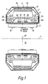
- the magnet is annular in construction and substantially symmetrical about its longitudinal axis 1.
- the magnet comprises an outer housing 2 within which is contained a vessel 3 which in use is filled with liquid helium.
- a heat shield 4 is positioned between the vessel 3 and the housing 2.
- the magnet comprises magnetising windings 5a, 5b and 6a, 6b and shield windings 7a, 7b which serve to contain the field produced by the magnetising windings 5a, 5b and 6a, 6b.
- the windings 7 are supported on a former 8 and the windings 5 and 6 are supported on formers 9 and 10 respectively.
- gradient coils 11 are provided within the bore 12 of the annular vessel.
- cold iron shim rings 13a and 13b are provided along side the windings 5a and 5b.
- shim rings 13a and 13b are effectively temperature stabilised, and by arranging that they are positionally fixed with respect to the windings 5a and 5b, they are rendered substantially insensitive to vibration which might otherwise produce differential movement between the shim rings 13a and 13b and their associated windings 5a and 5b.
- additional iron shim rings 14, 15 and 16 are provided in the form of warm iron which is positioned in the bore 12 adjacent to the gradient coils 11.
- the shim rings 14, 15 and 16 in the bore 12 are arranged to be substantially self compensating, i.e. instability produced by temperature changes and/or vibration in one shim is arranged to be compensated for by equal and opposite instability due to the other shim or shims.
- the theory behind this compensation has been earlier explained.
- a single pair of shim rings 14, 16 are provided symmetrically disposed with respect to the shim ring 15 which is centrally positioned.
- two pairs of shim rings 17a, 17b and 18a, 18b are provided arranged symmetrically about a central axis 19 orthogonal to the longitudinal axis 1.
- the choice of warm shim ring components is determined by the application in view and accordingly by the characteristics required.
- the sensitivity can be quantified in terms of the odd order amplitudes introduced per mm displacement of the shim set. This can also be translated into a pk-pk homogeneity shift on the imaging volume.
- a magnet according to the present invention may be made shorter by accepting a high degree of inhomogeneity of the field due to 'cold' components of the magnet, and then correcting this inhomogeneity using iron shims in the warm bore which serve as a 'self compensated' shim ring set such that the sensitivity with respect to temperature and/or vibrations normally associated with warm iron shim rings is compensated for.
- iron shims in the warm bore which serve as a 'self compensated' shim ring set such that the sensitivity with respect to temperature and/or vibrations normally associated with warm iron shim rings is compensated for.
Landscapes
- Physics & Mathematics (AREA)
- Condensed Matter Physics & Semiconductors (AREA)
- General Physics & Mathematics (AREA)
- Magnetic Resonance Imaging Apparatus (AREA)
Description
- This invention relates to electromagnets and more especially it relates to cryogenic electromagnets for use in magnetic resonance imaging (MRI) apparatus.
- It is a well understood requirement that magnets for MRI applications should provide a predetermined region of very high homogeneity magnetic field. This region, known as the imaging volume, is the region wherein that portion of a patient to be examined is positioned. It is comparatively easy to achieve high homogeneity with magnets having a relatively long axial length. However, long magnet bores tend to produce adverse patient reactions due to the effects of claustrophobia. Accordingly, it is highly desirable to reduce the axial length of magnets whereby the effects of claustrophobia are also reduced.
- In order to achieve shorter magnets, it is known to use iron in the magnet, whereby the field can be concentrated without sacrificing homogeneity to any significant extent. One such magnet is described in GB-A-2 276 945. In GB-A-2 276 945, an annular magnet for magnetic resonance imaging comprises an annular coil wound on an annular shim of magnetic material, the annular shim being coaxially disposed within the coil. Within the annular shim are located a plurality of magnet elements which interact with the fields produced by the coil and the annular shim to define a substantially homogeneous imaging field.
- Unfortunately, however, magnetisation of iron tends to be thermally sensitive which results in temperature related field fluctuations. Additionally, magnets which use iron can be vibration sensitive, which also results in magnetic field fluctuations due in this case to changes in the positional relationship between the iron and the magnet windings.
- GB-A-2 232 771 discloses a vessel in which iron is positioned within the vessel so that its temperature is stabilised, and so that the effects of vibration may also be reduced by mechanically anchoring the iron with respect to the magnet windings so that differential movement therebetween is minimised. However, because of the mass of iron required and because of other dimensional design considerations it may not be possible with short magnets to contain all of the iron required for optimum performance within the vessel without introducing other problems.
- It is an object of the present invention to provide a relatively short magnet with high tolerance of vibration and low sensitivity to temperature variations, or at least a magnet which is a good compromise between these desirable features, whereby a magnetic field is provided with an acceptably high degree of homogeneity as required for MRI applications.
- According to the present invention, a superconducting electromagnet for use in magnetic resonance imaging (MRI) apparatus comprising:-
- an annular vessel having a bore;
- annular windings located within the annular vessel, the windings being energisable to produce a magnetic field;
- a plurality of iron components located within the annular vessel and mechanically anchored with respect to the windings; and
- a plurality of shim rings positioned externally of the annular vessel and within its bore; characterised in that the plurality of shim rings comprises a shim ring set, the size and position of the shim rings of the shim ring set being chosen such that instability in the magnetic field introduced by one shim ring of the set due to vibration and/or temperature changes is compensated for by an equal and opposite instability produced by one or more of the other shim rings within the set.
-
- By containing most of the iron required within the vessel, problems related to vibration and temperature sensitivity are to some extent overcome and by arranging that the other iron required is in effect self compensating, field instability due to temperature and/or vibration can be substantially eliminated or at least significantly reduced.
- If the central magnetic field of a magnet according to the present invention is defined in terms of a spherical harmonic basis set, then in a cylindrical magnet exhibiting azimuthal symmetry, the field is given bywhere

- An = nth order harmonic amplitude
- R0 = Normalising Radius
- Pn = Legendre Polynomial of order n
-
- If the total field (cold iron + warm iron components) is defined in terms of the amplitudes B0 T and An T, the cold magnet field in terms of B0 C and An C and the field due to the ith warm iron ring pair in terms of B0 i and An i. Then the total field is related to the cold and warm fields by


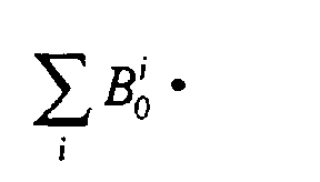
- Normally in magnet design B0 T and An T are optimised to achieve a predetermined field magnitude and homogeneity but in the present case additional constraints are introduced onand/or on

- Now, B0 i and An i are directly proportional to the saturation magnetisation of the rings, assuming the rings are axially magnetised to saturation. However, the saturation magnetisation of iron has a predetermined temperature sensitivity. Therefore, B0 i and An i also have a temperature sensitivity of the same size which translates into a temperature sensitivity in the magnet DC field (B0 T) and homogeneity (An T) respectively.
- Now, while it is impossible to modify the sensitivity of B0 i or of An i, it may be possible to find a shim set geometry such that


- Such a set is described as a zero order compensated and an nth order compensated shim set respectively.
- In this case, the thermal sensitivity of the compensated order is zero, provided any temperature change is the same for all i components. It is crucial to understand that there is also a differential sensitivity in the compensated order which becomes important when the shim temperatures diverge. The advantage is that it is easier to stabilise the relative temperature of the shims than it is to stabilise their absolute temperatures.
- Thus, in accordance with one embodiment of the invention, the warm iron comprises a shim ring set wherein instabilities in the zero-order term of the magnetic field of the shim ring set are compensated.
- In accordance with another aspect of the invention, the nth-order term of the magnetic field of the shim ring set is compensated.
- In accordance with a further aspect of the invention, both the zero-order term and the nth-order term of the magnetic field of the shim ring set are compensated, wherein n = 2.
- In order to achieve compensation, as aforesaid, one or more pairs of shim rings may be provided in accordance with the particular application in view.
- Some embodiments of the invention will now be described by way of example only, with reference to the accompanying drawings, in which:-
- FIGURE 1 is a sectional side view of a cryogenic magnet assembly which forms a part of an MRI system;
- FIGURE 2 is a sectional side view of an alternative cryogenic magnet for MRI applications;
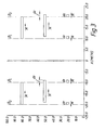
- FIGURE 3 is a diagram illustrating the effect of shim ring
displacement from a
central axis 19 as shown in Figure 2; and - FIGURE 4 is a graph of amplitudes Z1 and Z3 introduced by a pair of filamentary iron rings.
-
- Referring now to Figure 1, as can be seen from the drawing, the magnet is annular in construction and substantially symmetrical about its
longitudinal axis 1. The magnet comprises anouter housing 2 within which is contained avessel 3 which in use is filled with liquid helium. In order to improve thermal insulation aheat shield 4 is positioned between thevessel 3 and thehousing 2. The magnet comprisesmagnetising windings shield windings magnetising windings - In order to facilitate MRI operation,
gradient coils 11 are provided within thebore 12 of the annular vessel. Along side thewindings iron shim rings shim rings vessel 3, they are effectively temperature stabilised, and by arranging that they are positionally fixed with respect to thewindings shim rings windings - Although it is highly desirable to provide an arrangement as thus far described, wherein the iron is enclosed within the
vessel 3. For some applications it is not possible with the dimensional constraints imposed to contain all of the iron in the vessel. - Accordingly, additional
iron shim rings bore 12 adjacent to thegradient coils 11. As hereinbefore explained, theshim rings bore 12 are arranged to be substantially self compensating, i.e. instability produced by temperature changes and/or vibration in one shim is arranged to be compensated for by equal and opposite instability due to the other shim or shims. The theory behind this compensation has been earlier explained. - In the arrangement shown in Figure 1, a single pair of
shim rings shim ring 15 which is centrally positioned. - In an alternative arrangement however, as shown in Figure 2, wherein parts of the drawing which correspond to Figure 1 bear the same numerical designation, two pairs of
shim rings central axis 19 orthogonal to thelongitudinal axis 1. The choice of warm shim ring components is determined by the application in view and accordingly by the characteristics required. - The arrangement of Figure 1 serves to provide stabilised homogeneity whereas in Figure 2 the arrangement of shim rings has been chosen to provide optimum dc field stabilisation.
- The criteria for thermal sensitivity stabilisation has already been herein explained with reference to the theory involved. The criteria however for vibration sensitivity minimisation tends to be an empirically determined function which will now be considered.
- For a system of warm iron shim rings and coils, which are symmetrically disposed around the centre of a magnet, the odd orders (see equation 1) are zero. Now if the warm iron shim rings are displaced axially relative to the cold magnet, so that they are still concentric therewith but not symmetrically disposed about the central plane orthogonal with the longitudinal axis, then they will introduce some odd order amplitudes into the function as setforth in
equation 1. If the displacement is small enough, the even orders will be unchanged. - This can be shown by the following argument. First of all, define a filamentary pair of iron rings, having small cross sectional area, in terms of a parameter β, the ratio of the axial separation to the common diameter. Then consider the effect of displacing a pair of thin, iron rings through a small distance (dz). As illustrated in Figure 3, if the axial extent of the rings is defined by βL and βu, then this is equivalent to creating two pairs of rings of thickness dz at βL and βu. The elements of these rings are magnetised in opposite directions and therefore introduce only odd orders to the central field.
- This effect results in a sensitivity of the homogeneity to axial vibrations of the shim set relative to the cold magnet (non-axial vibrations are not considered). The sensitivity can be quantified in terms of the odd order amplitudes introduced per mm displacement of the shim set. This can also be translated into a pk-pk homogeneity shift on the imaging volume.
- But how can the vibrational sensitivity of a given shim configuration be estimated and optimised? In Figure 4, the first and third order harmonic amplitudes introduced by a pair of filamentary iron rings with opposite magnetisation are plotted as a function of β. These amplitudes are plotted for the case where the magnetisation vectors are pointing away from the mid plane of the magnet. For the opposite mode, the signs of the amplitudes are reversed. Notice from Figure 3 that the filamentary pairs created by the displacement have opposite modes of magnetisation. Therefore, a shim configuration such as shown in Figure 2 will introduce very little first order amplitude when displaced. Figure 4 also demonstrates that the vibrational sensitivity of a shim set is improved greatly of the shim set comprises more than one pair as shown in Figure 2, since there is much more scope for compensating the low order terms.
- It will be appreciated that a magnet according to the present invention may be made shorter by accepting a high degree of inhomogeneity of the field due to 'cold' components of the magnet, and then correcting this inhomogeneity using iron shims in the warm bore which serve as a 'self compensated' shim ring set such that the sensitivity with respect to temperature and/or vibrations normally associated with warm iron shim rings is compensated for. As will be readily apparent to the cognoscenti it is not possible to compensate against all factors simultaneously and accordingly a choice between homogeneity and the dc field will need to be made whereby satisfactory sensitivity to vibration can be determined according to the application envisaged.
Claims (9)
- A superconducting electromagnet for use in magnetic resonance imaging (MRI) apparatus comprising:-characterised in that the plurality of shim rings (14, 15, 16; 17a, 17b, 18a, 18b) comprises a shim ring set, the size and position of the shim rings (14, 15, 16; 17a, 17b, 18a, 18b) of the shim ring set being chosen such that instability in the magnetic field introduced by one shim ring of the set due to vibration and/or temperature changes is compensated for by an equal and opposite instability produced by one or more of the other shim rings within the set.an annular vessel (3) having a bore (12);annular windings (5a, 5b, 6a, 6b, 7a, 7b) located within the annular vessel (3), the windings (5a, 5b, 6a, 6b, 7a, 7b) being energisable to produce a magnetic field;a plurality of iron components (8, 9, 10, 13a, 13b) located within the annular vessel (3) and mechanically anchored with respect to the windings (5a, 5b, 6a, 6b, 7a, 7b); anda plurality of shim rings (14, 15, 16; 17a, 17b, 18a, 18b) positioned externally of the annular vessel (3) and within its bore (12);
- An electromagnet as claimed in Claim 1, wherein instabilities in the zero-order term of the magnetic field of the shim ring set are compensated.
- An electromagnet as claimed in Claim 1 or Claim 2, wherein the nth order term of the magnetic field of the shim ring set is compensated, and wherein n is preselected.
- An electromagnet as claimed in Claim 3, wherein both the zero-order term and the nth-order term of the magnetic field of the shim ring set are compensated, wherein n = 2.
- An electromagnet as claimed in any preceding claim, wherein the shim ring set includes at least one pair of shim rings (14, 16; 17a, 17b, 18a, 18b).
- An electromagnet as claimed in Claim 5, wherein said at least one pair of shim rings (14, 16) are arranged one on either side of a centrally disposed shim ring (15).
- An electromagnet as claimed in Claim 5, wherein the shim ring set includes two pairs of shim rings (17a, 17b, 18a, 18b).
- An electromagnet as claimed in any of Claims 5 to 7, wherein the shim rings (14, 15, 16; 17a, 17b, 17c) are symmetrically disposed about a central axis (19) orthogonal to the longitudinal axis (1) of the magnet.
- An electromagnet as claimed in any of Claims 5 to 7, wherein at least one pair of shim rings are offset with respect to a central axis (19) orthogonal to the longitudinal axis (1) of the magnet.
Applications Claiming Priority (2)
| Application Number | Priority Date | Filing Date | Title |
|---|---|---|---|
| GB9424069 | 1994-11-29 | ||
| GB9424069A GB2295672B (en) | 1994-11-29 | 1994-11-29 | Improvements in or relating to cryogenic MRI magnets |
Publications (2)
| Publication Number | Publication Date |
|---|---|
| EP0715181A1 EP0715181A1 (en) | 1996-06-05 |
| EP0715181B1 true EP0715181B1 (en) | 2002-04-17 |
Family
ID=10765151
Family Applications (1)
| Application Number | Title | Priority Date | Filing Date |
|---|---|---|---|
| EP95117309A Expired - Lifetime EP0715181B1 (en) | 1994-11-29 | 1995-11-03 | Improvements in or relating to cryogenic MRI magnets |
Country Status (5)
| Country | Link |
|---|---|
| US (1) | US5701112A (en) |
| EP (1) | EP0715181B1 (en) |
| JP (1) | JPH08224219A (en) |
| DE (1) | DE69526409T2 (en) |
| GB (1) | GB2295672B (en) |
Cited By (2)
| Publication number | Priority date | Publication date | Assignee | Title |
|---|---|---|---|---|
| US7224167B2 (en) | 2004-11-30 | 2007-05-29 | General Electric Company | Magnetic field generating apparatus and method for magnetic resonance imaging |
| US7439836B2 (en) | 2005-12-28 | 2008-10-21 | General Electric Company | Magnetic field generating apparatus for magnetic resonance imaging |
Families Citing this family (14)
| Publication number | Priority date | Publication date | Assignee | Title |
|---|---|---|---|---|
| EP0826978A1 (en) * | 1996-08-26 | 1998-03-04 | General Electric Company | Closed MRI magnet having compact design |
| US5874882A (en) * | 1998-02-19 | 1999-02-23 | General Electric Company | Open and shielded superconductive magnet |
| US6577125B2 (en) * | 2000-12-18 | 2003-06-10 | Halliburton Energy Services, Inc. | Temperature compensated magnetic field apparatus for NMR measurements |
| US6433550B1 (en) * | 2001-02-13 | 2002-08-13 | Koninklijke Philips Corporation N.V. | MRI magnet with vibration compensation |
| DE10217384C1 (en) * | 2002-04-18 | 2003-12-24 | Siemens Ag | gradient coil |
| WO2004099817A2 (en) | 2003-05-02 | 2004-11-18 | Halliburton Energy Services, Inc. | Systems and methods for nmr logging |
| EP1646884B1 (en) * | 2003-05-30 | 2015-01-07 | Koninklijke Philips N.V. | Magnetic resonance imaging scanner with molded fixed shims |
| GB2422201B (en) | 2003-10-03 | 2007-06-06 | Halliburton Energy Serv Inc | System And Methods For T1-Based Logging |
| US20090237076A1 (en) * | 2004-12-14 | 2009-09-24 | Koninklijke Philips Electronics N.V. | Magnetic resonance imaging apparatus, a method and a computer program for compensation of a field drift of the main magnet |
| JP4237786B2 (en) * | 2006-09-27 | 2009-03-11 | 株式会社日立製作所 | Nuclear magnetic resonance signal solenoid coil and nuclear magnetic resonance probe |
| DE102009045373B4 (en) * | 2009-10-06 | 2011-12-08 | Bruker Biospin Gmbh | A compact superconducting magnet arrangement with active shielding, wherein the shielding coil attenuates the field maximum of the main field coil |
| DE102010013890A1 (en) * | 2010-04-07 | 2011-10-13 | Siemens Aktiengesellschaft | Method and shim mass positioner for determining a shim mass arrangement |
| US8604793B2 (en) * | 2010-10-21 | 2013-12-10 | General Electric Company | Superconducting magnet having cold iron shimming capability |
| CN105324678B (en) | 2013-06-21 | 2018-11-20 | 皇家飞利浦有限公司 | Shim system for MRI hybrid scanners |
Family Cites Families (9)
| Publication number | Priority date | Publication date | Assignee | Title |
|---|---|---|---|---|
| DE3123493A1 (en) * | 1981-06-13 | 1982-12-30 | Bruker Analytische Meßtechnik GmbH, 7512 Rheinstetten | ELECTROMAGNET FOR NMR TOMOGRAPHY |
| DE3333755A1 (en) * | 1983-09-19 | 1985-04-18 | Siemens AG, 1000 Berlin und 8000 München | MAGNETIC DEVICE OF A SYSTEM OF CORE SPIN TOMOGRAPHY WITH A SHIELDING DEVICE |
| US4587504A (en) * | 1983-11-11 | 1986-05-06 | Oxford Magnet Technology Limited | Magnet assembly for use in NMR apparatus |
| US4743880A (en) * | 1987-09-28 | 1988-05-10 | Ga Technologies Inc. | MRI magnet system having shield and method of manufacture |
| NL9001300A (en) * | 1990-06-08 | 1992-01-02 | Koninkl Philips Electronics Nv | MAGNETIC SYSTEM FOR MAGNETIC RESONANCE. |
| FR2667948B1 (en) * | 1990-10-12 | 1993-04-16 | Magnetech | MAGNETIC SYSTEM WITH HOMOGENEOUS FIELD OF HIGH ACCESSIBILITY. |
| US5124651A (en) * | 1990-10-24 | 1992-06-23 | Fonar Corporation | Nuclear magnetic resonance scanners with composite pole facings |
| GB2276945B (en) * | 1993-04-08 | 1997-02-26 | Oxford Magnet Tech | Improvements in or relating to MRI magnets |
| FI105293B (en) * | 1993-06-08 | 2000-07-14 | Picker Nordstar Oy | Polsko for a magnet used in magnetic resonance imaging |
-
1994
- 1994-11-29 GB GB9424069A patent/GB2295672B/en not_active Expired - Fee Related
-
1995
- 1995-11-03 DE DE69526409T patent/DE69526409T2/en not_active Expired - Fee Related
- 1995-11-03 EP EP95117309A patent/EP0715181B1/en not_active Expired - Lifetime
- 1995-11-13 US US08/556,601 patent/US5701112A/en not_active Expired - Lifetime
- 1995-11-28 JP JP7309341A patent/JPH08224219A/en not_active Ceased
Cited By (2)
| Publication number | Priority date | Publication date | Assignee | Title |
|---|---|---|---|---|
| US7224167B2 (en) | 2004-11-30 | 2007-05-29 | General Electric Company | Magnetic field generating apparatus and method for magnetic resonance imaging |
| US7439836B2 (en) | 2005-12-28 | 2008-10-21 | General Electric Company | Magnetic field generating apparatus for magnetic resonance imaging |
Also Published As
| Publication number | Publication date |
|---|---|
| EP0715181A1 (en) | 1996-06-05 |
| GB9424069D0 (en) | 1995-01-18 |
| GB2295672A (en) | 1996-06-05 |
| GB2295672B (en) | 1999-05-12 |
| JPH08224219A (en) | 1996-09-03 |
| US5701112A (en) | 1997-12-23 |
| DE69526409D1 (en) | 2002-05-23 |
| DE69526409T2 (en) | 2002-11-07 |
Similar Documents
| Publication | Publication Date | Title |
|---|---|---|
| US5701112A (en) | Cryogenic MRI magnets | |
| EP0715180B1 (en) | Cryogenic MRI magnets | |
| US7567083B2 (en) | Superconductive magnetic apparatus for magnetic resonance imaging unit | |
| US5574417A (en) | Open MRI magnet with homogeneous imaging volume | |
| JPH09153408A (en) | Superconducting magnet device | |
| JPS6098343A (en) | Nuclear magnetic resonance device | |
| EP0770883A1 (en) | Cryogenic-fluid-cooled open MRI magnet with uniform magnetic field | |
| EP0334382A1 (en) | Magnet apparatus for use in magnetic resonance imaging system | |
| EP0819948B1 (en) | Superconducting MR yoke magnet and method of energizing same | |
| US9766312B2 (en) | Easily accessible deep-frozen NMR shim arrangement | |
| EP0770882B1 (en) | Open MRI superconductive magnet with cryogenic-fluid cooling | |
| US5396208A (en) | Magnet system for magnetic resonance imaging | |
| JPH09223620A (en) | Open type electromagnet | |
| US5939962A (en) | Split type magnetic field generating apparatus for MRI | |
| US5384538A (en) | Magnetic field generation device for use in superconductive type MRI | |
| EP1531337A1 (en) | Superconducting magnet apparatus and magnetic resonance imaging apparatus using the same | |
| US5521571A (en) | Open MRI magnet with uniform imaging volume | |
| EP0936290B1 (en) | Superconducting magnet device for crystal pulling device | |
| US20020135450A1 (en) | Open magnet with recessed field shaping coils | |
| US5038129A (en) | Electromagnetic having magnetic shield | |
| US4800355A (en) | Electromagnet having magnetic shield | |
| JP2000037366A (en) | Superconductive magnet device | |
| US7005953B2 (en) | Magnet system with shielded regenerator material | |
| US5534779A (en) | Magnet systems | |
| US6504372B1 (en) | High field open magnetic resonance magnet with reduced vibration |
Legal Events
| Date | Code | Title | Description |
|---|---|---|---|
| PUAI | Public reference made under article 153(3) epc to a published international application that has entered the european phase |
Free format text: ORIGINAL CODE: 0009012 |
|
| AK | Designated contracting states |
Kind code of ref document: A1 Designated state(s): DE FR GB |
|
| 17P | Request for examination filed |
Effective date: 19961015 |
|
| 17Q | First examination report despatched |
Effective date: 19980224 |
|
| GRAG | Despatch of communication of intention to grant |
Free format text: ORIGINAL CODE: EPIDOS AGRA |
|
| GRAG | Despatch of communication of intention to grant |
Free format text: ORIGINAL CODE: EPIDOS AGRA |
|
| GRAG | Despatch of communication of intention to grant |
Free format text: ORIGINAL CODE: EPIDOS AGRA |
|
| GRAH | Despatch of communication of intention to grant a patent |
Free format text: ORIGINAL CODE: EPIDOS IGRA |
|
| GRAG | Despatch of communication of intention to grant |
Free format text: ORIGINAL CODE: EPIDOS AGRA |
|
| REG | Reference to a national code |
Ref country code: GB Ref legal event code: IF02 |
|
| GRAH | Despatch of communication of intention to grant a patent |
Free format text: ORIGINAL CODE: EPIDOS IGRA |
|
| GRAG | Despatch of communication of intention to grant |
Free format text: ORIGINAL CODE: EPIDOS AGRA |
|
| GRAA | (expected) grant |
Free format text: ORIGINAL CODE: 0009210 |
|
| AK | Designated contracting states |
Kind code of ref document: B1 Designated state(s): DE FR GB |
|
| REF | Corresponds to: |
Ref document number: 69526409 Country of ref document: DE Date of ref document: 20020523 |
|
| ET | Fr: translation filed | ||
| PLBE | No opposition filed within time limit |
Free format text: ORIGINAL CODE: 0009261 |
|
| STAA | Information on the status of an ep patent application or granted ep patent |
Free format text: STATUS: NO OPPOSITION FILED WITHIN TIME LIMIT |
|
| 26N | No opposition filed |
Effective date: 20030120 |
|
| PGFP | Annual fee paid to national office [announced via postgrant information from national office to epo] |
Ref country code: FR Payment date: 20031110 Year of fee payment: 9 |
|
| PG25 | Lapsed in a contracting state [announced via postgrant information from national office to epo] |
Ref country code: FR Free format text: LAPSE BECAUSE OF NON-PAYMENT OF DUE FEES Effective date: 20050729 |
|
| REG | Reference to a national code |
Ref country code: FR Ref legal event code: ST |
|
| PGFP | Annual fee paid to national office [announced via postgrant information from national office to epo] |
Ref country code: DE Payment date: 20070420 Year of fee payment: 12 |
|
| PG25 | Lapsed in a contracting state [announced via postgrant information from national office to epo] |
Ref country code: DE Free format text: LAPSE BECAUSE OF NON-PAYMENT OF DUE FEES Effective date: 20080603 |
|
| REG | Reference to a national code |
Ref country code: GB Ref legal event code: 732E Free format text: REGISTERED BETWEEN 20090423 AND 20090429 |
|
| PGFP | Annual fee paid to national office [announced via postgrant information from national office to epo] |
Ref country code: GB Payment date: 20091112 Year of fee payment: 15 |
|
| GBPC | Gb: european patent ceased through non-payment of renewal fee |
Effective date: 20101103 |
|
| PG25 | Lapsed in a contracting state [announced via postgrant information from national office to epo] |
Ref country code: GB Free format text: LAPSE BECAUSE OF NON-PAYMENT OF DUE FEES Effective date: 20101103 |