EP0714342B1 - Method for cutting elongated tube - Google Patents
Method for cutting elongated tube Download PDFInfo
- Publication number
- EP0714342B1 EP0714342B1 EP93920254A EP93920254A EP0714342B1 EP 0714342 B1 EP0714342 B1 EP 0714342B1 EP 93920254 A EP93920254 A EP 93920254A EP 93920254 A EP93920254 A EP 93920254A EP 0714342 B1 EP0714342 B1 EP 0714342B1
- Authority
- EP
- European Patent Office
- Prior art keywords
- tube
- kerf
- walls
- kerfs
- severing
- Prior art date
- Legal status (The legal status is an assumption and is not a legal conclusion. Google has not performed a legal analysis and makes no representation as to the accuracy of the status listed.)
- Expired - Lifetime
Links
Images



Classifications
-
- B—PERFORMING OPERATIONS; TRANSPORTING
- B23—MACHINE TOOLS; METAL-WORKING NOT OTHERWISE PROVIDED FOR
- B23D—PLANING; SLOTTING; SHEARING; BROACHING; SAWING; FILING; SCRAPING; LIKE OPERATIONS FOR WORKING METAL BY REMOVING MATERIAL, NOT OTHERWISE PROVIDED FOR
- B23D31/00—Shearing machines or shearing devices covered by none or more than one of the groups B23D15/00 - B23D29/00; Combinations of shearing machines
- B23D31/002—Breaking machines, i.e. pre-cutting and subsequent breaking
Definitions
- This invention relates to a method for cutting tubular stock and in particular to a method for cutting flat tubular stock of the type defining a series of parallel generally rectangular longitudinally extending passages.
- Flat tubular stock defining multiple parallel passages has many industrial applications including the fabrication of condensers for air conditioner systems.
- condensers for air conditioner systems.
- This invention is directed to the provision of improved method for severing flat tubular stock.
- this invention is directed to the provision of a method for severing flat tubular stock to eliminate the necessity for any secondary finishing or resizing operations following the severing operation.
- a method of severing an elongated tube comprising the steps of forming a first transverse kerf in one side of the tube, forming a second transverse kerf, lying in a common transverse plane with the said first kerf, in an opposite side of the tube, and exerting a relative pulling force on the tube sections on opposite sides of the transverse plane to tear apart the remaining tube material at the plane and sever the tube, each kerf having a depth slightly less than the thickness of the wall of the tube, characterised in that the kerfs are formed in a broaching operation comprising a first cut in which a generally V-shaped narrow angle kerf is formed and a second cut in which the kerf is widened to provide a wide generally V-shaped wide angle cut.
- This methodology effectively removes a large percentage of the tube material at the cutting plane in the process of forming the kerfs so that a relatively small amount of tube material is actually torn apart in the final pulling operation so as to minimize the formation of burrs or other irregularities at the severed edge of the tube and eliminate the need for any further finishing or resizing operation.
- broaching operation ensures that the material of the tube is cleanly and totally removed in the formation of the kerfs so as to further minimize the amount of material that must be torn apart in the final pulling operation.
- the two kerfs are formed simultaneously and the pulling force is exerted after the kerfs have been formed.
- This specific methodology provides for a precise, positive severing of the tube at the kerf location.
- the broaching operation comprises a first cut in which a narrow, generally V-shaped narrow angle kerf is formed and a second cut in which the kerf is widened to provide a wide generally V-shaped wide angle cut.
- the first cut establishes the depth and location of the kerf and the second cut removes any burrs formed by the first cut and creates a shallow chamfer to facilitate mounting of the tube section in correspondingly chamfered seats on the header of an associated condenser.
- the invention is especially suitable for use with elongated flat metal tube stock of the type having upper and lower flat horizontal walls, vertical end edge walls, and vertical partition walls spaced between the end edge walls and interconnecting the upper and lower walls to divide the tube into a series of parallel, generally rectangular, longitudinally extending passages.
- a transverse kerf is formed in the upper wall lying in a transverse plane
- a transverse kerf is formed in the lower wall lying in the transverse plane
- relative pulling force is exerted on the tube sections on opposite sides of the transverse plane to tear apart the remaining tube material at the plane and sever the tube.
- a tube is fed along a longitudinal feed path to position a portion of the tube at a severing station, a first clamp is engaged with the tube at one side of the severing station and a second clamp is engaged with the tube at the other side of the severing station, transverse kerfs are simultaneously formed in the upper and lower walls of the tube at the severing station, and the first and second clamps are thereafter moved longitudinally relatively apart to tear apart the remaining tube material and sever the tube.
- each kerf has a depth slightly less than the thickness of the respective upper and lower tube walls so as to leave only a small amount of solid tube material between the base or root of the respective kerf and the adjacent wall surfaces of the passages of the tube.
- the invention apparatus is of the type including means for feeding the stock along a longitudinal feed path to position a portion of the tube at a severing station, means for weakening the tube at the severing station, and means for tearing apart the tube at the weakened location.
- the weakening means comprises a slide mounted at the severing station for transverse movement across the feed path and upper and lower knives mounted on the slide and positioned to form respective kerfs in the upper and lower walls of the flat tubular stock as the slide is moved across the feed path.
- each knife comprises a broaching knife including a leading tooth, sized to form a narrow, generally V-shaped kerf in the respective tube wall, and a trailing tooth, sized to widen the kerf and provide a wide, generally V-shaped wide angle kerf.
- This specific knife construction allows the first or leading tooth to establish the depth and location of the kerf in the respective wall and allows the trailing tooth to remove any burrs formed by the first tooth and provide a shallow chamfer configuration to the kerf to facilitate mounting of the severed tube sections in chamfered seats in the header of an associated condenser.
- the invention method and apparatus is especially suitable for severing flat aluminum tubing of the type seen in Figure 1 and including upper and lower flat horizontal walls 10a and 10b, vertical edge walls 10c, and vertical partitions 10d spaced between the end edge walls and interconnecting the upper and lower walls to divide the tube into a series of parallel, generally rectangular, longitudinally extending cores or passages 10e.
- Tubing of this type is used, for example, in forming condensers for air conditioning systems for motor vehicles.
- Flat aluminum tubing 10 supplied in roll form is severed to provide preselected lengths of flat tubing which are combined with the headers of the condenser to form the condenser assembly.
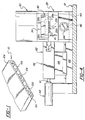
- the invention apparatus includes a base 12, a roll stand 14 to hold a roll 16 of flat tubular stock 10, a pair of feed or drive rolls 18 adapted to engage the upper and lower walls of flat tubular stock 10 and feed the stock in the direction indicated by the arrows, a stationary clamp assembly 20, a movable clamp assembly 24, and a cross slide assembly 26.
- Stationary clamp assembly 20 includes a fixed lower clamp member 28 supported on base 12, a power cylinder 30 supported on fixed lower clamp member 28, and a movable upper clamp member 32 carried by the piston rod 34 of cylinder 30 and movable into and out of clamping coaction with fixed lower clamp member 28 in response to actuation of cylinder 30 whereby to clamp or release tubular stock 10 fed therebetween.
- the upper face 28a of lower clamp member 28 may be provided with a sculptured recess as seen at 28b to facilitate the clamping of tubular stock 10 between face 28a and the lower face 32a of the upper clamp 32.
- Upper clamp 32 and lower clamp 28 also include tapered nose portions 32b and 28c proximate cross slide assembly 26.
- Movable clamp assembly 24 includes a lower clamp member 40 mounted for sliding longitudinal movement on a rail 42 mounted on base 12; a hydraulic cylinder 44 positioned beneath the lower clamp member 28 of clamp assembly 20 and including a piston rod 26 connected to lower clamp member 40 of clamp assembly 24 so as to move the clamp assembly 24 in reciprocal fashion along rail 42 in response to actuation of cylinder 44; a power cylinder 48 mounted on lower clamp member 40; and an upper clamp 50 secured to the lower end of the piston rod 52 of cylinder 48 whereby the upper clamp 50 may be moved into and out of clamping relation with lower clamp 40 in response to actuation of cylinder 48 to clamp or release tubular stock 10 fed therebetween.
- Upper clamp 50 and lower clamp 40 also each include a tapered nose portion 50a and 40a corresponding generally in size and configuration to the nose portions 32b and 28c of lower clamp members 28 and 32.
- nose portion 28c, nose portion 40a, and lower clamp member 40 are provided with a sculptured recess corresponding to the recess 28b in the upper face of clamp member 28.
- nose portions 32b and 28c are spaced from the rearward edges of nose portions 50a and 40a to define a severing station 60 between the spaced nose portions.
- Cross slide assembly 26 includes a cross slide 62, a bracket 64 mounting the cross slide for sliding movement in a direction transverse to the longtitudinal feed path of the tubular stock 10 along a track 66 positioned on the upper face of base 12, and a power cylinder 68 mounted on base 12 and including a piston rod 61 engaging cross slide 62 so that the cross slide is moved in a direction transverse to the feed path of the tube stock in response to actuation of cylinder 68.
- Cross slide 62 includes a main body portion 62a and a yoke portion 62b including spaced upper and lower arm portions 62c and 62d.
- a broaching knife 70 is suitably mounted on each arm 62c, 62d (as for example by bolts 72) with the knives confronting but spaced from each other as best seen in Figure 7.
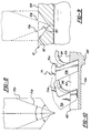
- Each broaching knife 70 includes a main body portion 70a for mounting in the respective arm 62c, 62d of the cross slide, a leading tooth 70b, and a trailing tooth 70c.
- Leading tooth 70b presents a narrow V-shaped profile and may for example have an included angle ⁇ of 42°.
- Trailing tooth 70c has a shallow wide V-shaped profile and may for example have an included angle ⁇ of 120°.
- the extreme lower edge of tooth 70b is preferably spaced somewhat below the extreme lower edge of tooth 70c.
- the lower edge of tooth 70b may be spaced 0.0178 cm (0.0070 inches) below the lower edge of tooth 70c.
- tooth 70b The front or leading edge of tooth 70b is cut away at 70d to facilitate chip curling and chip removal; the area 70e between tooth 70b and tooth 70c is cut away to further facilitate chip curling and chip removal; and the area 70f rearwardly of tooth 70c is relieved to further facilitate chip curling and chip removal.
- flat tube stock 10 is fed from roll 16 by feed rollers 18 and moves along a longitudinal teed path defined along the upper face of lower clamp 28 and the upper face of lower clamp 40 until the leading end 10a of the tube stock reaches a preselected position, as determined by a preselected number of rotations of feed rollers 18 corresponding to a preselected length of tube stock to be severed, whereafter cylinders 30 and 48 are actuated to lower clamps 32 and 50 to clampingly secure the cube stock at opposite sides of the severing station 60.
- Cross slide 62 is thereafter moved transversely across the feed path of the tube stock by suitable actuation of cylinder 68.
- teeth 70b of the upper and lower knives 70 engage the upper and lower walls 10a and 10b of the tube stock and, as the cross slide is moved across the feed path of the tube stock, remove tube material to form a narrow, generally V-shaped narrow angle kerf 80 in the upper and lower walls 10a and 10b of the tube stock.
- the following or trailing teeth 70c remove further tube material and act to widen the respective kerfs formed by the teeth 70b to provide a wide, generally V-shaped wide angle kerf 82 in the upper and lower tube walls.
- the cylinder 68 is actuated in a sense to return the cross slide to its rest position of Figure 7 whereafter cylinder 44 is actuated in a sense to move clamp assembly 24 forwardly or to the right as viewed in Figure 2 so as to exert a relative pulling force on the tube at opposite sides of the weakened portion formed by the kerfs 82, whereby to tear apart the remaining tube material in the plane of the kerfs and sever the tube.
- the severed section is thereafter removed from the apparatus and the apparatus is prepared for the next successive severing operation.
- the depth of the kerfs 80 and 82 is preferably only slightly less than the thickness of the walls 10a and 10b of the tube stock so that, after the removal of tube material by the broaching knives to form the kerfs, only a small amount of tube material in the upper and lower walls 10a and 10b remains to be severed by the pulling or tearing operation.
- the depth of kerfs 80 and 82 may approximate 0.030 cm (0.012 inches). Since only a small amount of material is severed or torn in the pulling operation, only very minor burr formations are created at the severed edge of the tube and the passageways 10e remain totally intact with virtually no distortion or deformation from their original rectangular shape.
- the invention method will thus be seen to provide a flat tube severing technique which requires no subsequent finishing or resizing operations and which provides a chamfered surface on the severed edge of the tube section to facilitate the subsequent assembly of the tube sections into the final condenser assembly.
Landscapes
- Engineering & Computer Science (AREA)
- Mechanical Engineering (AREA)
- Sawing (AREA)
- Re-Forming, After-Treatment, Cutting And Transporting Of Glass Products (AREA)
- Mechanical Treatment Of Semiconductor (AREA)
- Processing Of Stones Or Stones Resemblance Materials (AREA)
- Metal Extraction Processes (AREA)
- Perforating, Stamping-Out Or Severing By Means Other Than Cutting (AREA)
- Rigid Pipes And Flexible Pipes (AREA)
Abstract
Description
Claims (6)
- A method of severing an elongated tube comprising the steps of forming a first transverse kerf in one side of the tube, forming a second transverse kerf, lying in a common transverse plane with the said first kerf, in an opposite side of the tube, and exerting a relative pulling force on the tube sections on opposite sides of the transverse plane to tear apart the remaining tube material at the plane and sever the tube, each kerf having a depth slightly less than the thickness of the wall of the tube, characterised in that the kerfs are formed in a broaching operation comprising a first cut in which a generally V-shaped narrow angle kerf is formed and a second cut in which the kerf is widened to provide a wide generally V-shaped wide angle cut.
- A method according to claim 1 wherein the first narrow angle kerf is an acute angle kerf and the second wide angle kerf is an obtuse angle kerf.
- A method according to claim 1 wherein the tube is a flat tube having upper and lower flat horizontal walls, vertical edge walls, and vertical partition walls spaced between the end edge walls and interconnecting the upper and lower walls to divide the tube into a series of parallel generally rectangular longitudinally extending passages, the first kerf is formed in the upper wall of the tube, and the second kerf is formed in the lower wall of the tube.
- A method according to claims 1 - 3 wherein the two kerfs are formed simultaneously and the pulling force is exerted after the kerfs have been formed.
- A method according to claims 1 - 4 wherein the tube is fed along a longitudinal feed path to position a portion of the tube at a severing station, a first clamp is engaged with the tube at one side of the severing station, a second clamp is engaged with the tube at the other side of the severing station leaving a length of tubing exposed between the clamps at the severing stations.
- A method according to claim 5 wherein the first and second clamps are moved longitudinally apart to tear apart the tube material remaining between the kerfs and sever the tube.
Applications Claiming Priority (2)
| Application Number | Priority Date | Filing Date | Title |
|---|---|---|---|
| US07/833,051 US5249345A (en) | 1992-02-10 | 1992-02-10 | Method for cutting elongated tube stock |
| PCT/US1993/007858 WO1995005926A1 (en) | 1992-02-10 | 1993-08-20 | Method for cutting elongated tube |
Publications (3)
| Publication Number | Publication Date |
|---|---|
| EP0714342A1 EP0714342A1 (en) | 1996-06-05 |
| EP0714342A4 EP0714342A4 (en) | 1998-02-25 |
| EP0714342B1 true EP0714342B1 (en) | 2000-04-19 |
Family
ID=26786971
Family Applications (1)
| Application Number | Title | Priority Date | Filing Date |
|---|---|---|---|
| EP93920254A Expired - Lifetime EP0714342B1 (en) | 1992-02-10 | 1993-08-20 | Method for cutting elongated tube |
Country Status (6)
| Country | Link |
|---|---|
| EP (1) | EP0714342B1 (en) |
| AT (1) | ATE191874T1 (en) |
| DE (1) | DE69328446T2 (en) |
| DK (1) | DK0714342T3 (en) |
| ES (1) | ES2145057T3 (en) |
| WO (1) | WO1995005926A1 (en) |
Cited By (3)
| Publication number | Priority date | Publication date | Assignee | Title |
|---|---|---|---|---|
| DE10212309C1 (en) * | 2002-03-20 | 2003-02-13 | Erbsloeh Aluminium Gmbh | Separation method for aluminium or aluminium alloy flat tubular profiles has solder coating removed from flat tubular profile at separation point before separation |
| DE102009036006B3 (en) * | 2009-08-04 | 2010-12-30 | Modine Manufacturing Co., Racine | Method for producing metallic tube of heat exchanger, involves breaking tubes at breaking points between roller pairs, where tubes are loaded with laminar contact pressure during breaking and sufficient breaking load is transmitted to tubes |
| DE102010023384A1 (en) | 2010-06-10 | 2011-12-15 | Modine Manufacturing Co. | Manufacturing process, in particular for pipes and tear-off device |
Families Citing this family (1)
| Publication number | Priority date | Publication date | Assignee | Title |
|---|---|---|---|---|
| CN112589868B (en) * | 2020-11-25 | 2022-05-03 | 太原龙投富思特新材料科技有限公司 | Preparation and processing method of external wall heat-insulation decorative material |
Family Cites Families (3)
| Publication number | Priority date | Publication date | Assignee | Title |
|---|---|---|---|---|
| US3757627A (en) * | 1970-06-18 | 1973-09-11 | Wafios Maschinen Wagner | Method and apparatus for cutting pins for producing chain links |
| US5133492A (en) * | 1990-12-19 | 1992-07-28 | Peerless Of America, Incorporated | Method and apparatus for separating thin-walled, multiport micro-extrusions |
| US5143268A (en) * | 1991-07-17 | 1992-09-01 | Crown Unlimited Machine, Inc. | Flat tube cutting techniques |
-
1993
- 1993-08-20 EP EP93920254A patent/EP0714342B1/en not_active Expired - Lifetime
- 1993-08-20 DE DE69328446T patent/DE69328446T2/en not_active Expired - Fee Related
- 1993-08-20 DK DK93920254T patent/DK0714342T3/en active
- 1993-08-20 ES ES93920254T patent/ES2145057T3/en not_active Expired - Lifetime
- 1993-08-20 AT AT93920254T patent/ATE191874T1/en active
- 1993-08-20 WO PCT/US1993/007858 patent/WO1995005926A1/en not_active Ceased
Cited By (4)
| Publication number | Priority date | Publication date | Assignee | Title |
|---|---|---|---|---|
| DE10212309C1 (en) * | 2002-03-20 | 2003-02-13 | Erbsloeh Aluminium Gmbh | Separation method for aluminium or aluminium alloy flat tubular profiles has solder coating removed from flat tubular profile at separation point before separation |
| DE102009036006B3 (en) * | 2009-08-04 | 2010-12-30 | Modine Manufacturing Co., Racine | Method for producing metallic tube of heat exchanger, involves breaking tubes at breaking points between roller pairs, where tubes are loaded with laminar contact pressure during breaking and sufficient breaking load is transmitted to tubes |
| DE102010023384A1 (en) | 2010-06-10 | 2011-12-15 | Modine Manufacturing Co. | Manufacturing process, in particular for pipes and tear-off device |
| DE102010023384B4 (en) * | 2010-06-10 | 2014-08-28 | Modine Manufacturing Co. | Manufacturing process, in particular for pipes and tear-off device |
Also Published As
| Publication number | Publication date |
|---|---|
| DE69328446D1 (en) | 2000-05-25 |
| EP0714342A4 (en) | 1998-02-25 |
| ATE191874T1 (en) | 2000-05-15 |
| ES2145057T3 (en) | 2000-07-01 |
| WO1995005926A1 (en) | 1995-03-02 |
| DE69328446T2 (en) | 2000-12-07 |
| EP0714342A1 (en) | 1996-06-05 |
| DK0714342T3 (en) | 2000-09-18 |
Similar Documents
| Publication | Publication Date | Title |
|---|---|---|
| US5249345A (en) | Method for cutting elongated tube stock | |
| US5201117A (en) | Method and apparatus for sizing and cutting tubing | |
| US2120316A (en) | Apparatus for welding and flash trimmings | |
| US3866286A (en) | Method of making a finned tube heat exchanger having a circular cross section | |
| US5143268A (en) | Flat tube cutting techniques | |
| JPH11333530A (en) | Metal sheet punching method and punching tool | |
| US3938413A (en) | Extrusion preparation apparatus | |
| EP0714342A1 (en) | Method for cutting elongated tube | |
| PL172278B1 (en) | Method and device for producing parts from sheet metal PL | |
| US20080276774A1 (en) | Sheet metal section | |
| US4353235A (en) | Edge preforming of metal plate | |
| JPH06155140A (en) | Method and device for cutting cold pilger rolled pipe into shortened length | |
| US4476703A (en) | Edge preforming of metal plate | |
| US5388745A (en) | Method and apparatus for separating tubing | |
| CN215587974U (en) | On-line hot longitudinal cutting machine set for high-temperature steel plate | |
| WO2014021251A1 (en) | Cold working method for band-shaped workpieces, device therefor, and long sheet-shaped product | |
| JP2002137114A (en) | Method for cutting pipe member and device thereof | |
| JPH08206828A (en) | Butt welding process and cutting equipment | |
| DE2658184A1 (en) | Internal deburring unit small dia. welded pipe - has pressure roller to profile burr which is then removed by adjustable broaching tool hydraulically | |
| JPH0642018U (en) | Cutting device for thin metal tubes | |
| CN216966411U (en) | Flash removing device for headless rolling square billet | |
| JPS60255202A (en) | Push cutting method | |
| US777947A (en) | Method of manufacturing brake-shoe keys. | |
| US6928910B2 (en) | Method for separating a flat pipe section of aluminum or aluminum alloy from a solder-coated thin-walled flat pipe section member | |
| CN1022385C (en) | Connecting method for rolling stocks |
Legal Events
| Date | Code | Title | Description |
|---|---|---|---|
| PUAI | Public reference made under article 153(3) epc to a published international application that has entered the european phase |
Free format text: ORIGINAL CODE: 0009012 |
|
| 17P | Request for examination filed |
Effective date: 19960208 |
|
| AK | Designated contracting states |
Kind code of ref document: A1 Designated state(s): AT BE CH DE DK ES FR GB GR IE IT LI LU MC NL PT SE |
|
| RIN1 | Information on inventor provided before grant (corrected) |
Inventor name: MCCARBERY, HENRY Inventor name: VIRSIK, MILAN |
|
| A4 | Supplementary search report drawn up and despatched |
Effective date: 19980108 |
|
| AK | Designated contracting states |
Kind code of ref document: A4 Designated state(s): AT BE CH DE DK ES FR GB GR IE IT LI LU MC NL PT SE |
|
| 17Q | First examination report despatched |
Effective date: 19981016 |
|
| GRAG | Despatch of communication of intention to grant |
Free format text: ORIGINAL CODE: EPIDOS AGRA |
|
| GRAG | Despatch of communication of intention to grant |
Free format text: ORIGINAL CODE: EPIDOS AGRA |
|
| GRAH | Despatch of communication of intention to grant a patent |
Free format text: ORIGINAL CODE: EPIDOS IGRA |
|
| GRAH | Despatch of communication of intention to grant a patent |
Free format text: ORIGINAL CODE: EPIDOS IGRA |
|
| GRAA | (expected) grant |
Free format text: ORIGINAL CODE: 0009210 |
|
| AK | Designated contracting states |
Kind code of ref document: B1 Designated state(s): AT BE CH DE DK ES FR GB GR IE IT LI LU MC NL PT SE |
|
| PG25 | Lapsed in a contracting state [announced via postgrant information from national office to epo] |
Ref country code: LI Free format text: LAPSE BECAUSE OF FAILURE TO SUBMIT A TRANSLATION OF THE DESCRIPTION OR TO PAY THE FEE WITHIN THE PRESCRIBED TIME-LIMIT Effective date: 20000419 Ref country code: GR Free format text: LAPSE BECAUSE OF NON-PAYMENT OF DUE FEES Effective date: 20000419 Ref country code: CH Free format text: LAPSE BECAUSE OF FAILURE TO SUBMIT A TRANSLATION OF THE DESCRIPTION OR TO PAY THE FEE WITHIN THE PRESCRIBED TIME-LIMIT Effective date: 20000419 Ref country code: BE Free format text: LAPSE BECAUSE OF FAILURE TO SUBMIT A TRANSLATION OF THE DESCRIPTION OR TO PAY THE FEE WITHIN THE PRESCRIBED TIME-LIMIT Effective date: 20000419 Ref country code: AT Free format text: LAPSE BECAUSE OF FAILURE TO SUBMIT A TRANSLATION OF THE DESCRIPTION OR TO PAY THE FEE WITHIN THE PRESCRIBED TIME-LIMIT Effective date: 20000419 |
|
| REF | Corresponds to: |
Ref document number: 191874 Country of ref document: AT Date of ref document: 20000515 Kind code of ref document: T |
|
| REG | Reference to a national code |
Ref country code: CH Ref legal event code: EP |
|
| REF | Corresponds to: |
Ref document number: 69328446 Country of ref document: DE Date of ref document: 20000525 |
|
| REG | Reference to a national code |
Ref country code: IE Ref legal event code: FG4D |
|
| ET | Fr: translation filed | ||
| REG | Reference to a national code |
Ref country code: ES Ref legal event code: FG2A Ref document number: 2145057 Country of ref document: ES Kind code of ref document: T3 |
|
| ITF | It: translation for a ep patent filed | ||
| PG25 | Lapsed in a contracting state [announced via postgrant information from national office to epo] |
Ref country code: SE Free format text: LAPSE BECAUSE OF FAILURE TO SUBMIT A TRANSLATION OF THE DESCRIPTION OR TO PAY THE FEE WITHIN THE PRESCRIBED TIME-LIMIT Effective date: 20000719 Ref country code: PT Free format text: LAPSE BECAUSE OF FAILURE TO SUBMIT A TRANSLATION OF THE DESCRIPTION OR TO PAY THE FEE WITHIN THE PRESCRIBED TIME-LIMIT Effective date: 20000719 |
|
| PG25 | Lapsed in a contracting state [announced via postgrant information from national office to epo] |
Ref country code: LU Free format text: LAPSE BECAUSE OF NON-PAYMENT OF DUE FEES Effective date: 20000820 |
|
| PG25 | Lapsed in a contracting state [announced via postgrant information from national office to epo] |
Ref country code: MC Free format text: THE PATENT HAS BEEN ANNULLED BY A DECISION OF A NATIONAL AUTHORITY Effective date: 20000831 |
|
| REG | Reference to a national code |
Ref country code: DK Ref legal event code: T3 |
|
| REG | Reference to a national code |
Ref country code: CH Ref legal event code: PL |
|
| PLBE | No opposition filed within time limit |
Free format text: ORIGINAL CODE: 0009261 |
|
| STAA | Information on the status of an ep patent application or granted ep patent |
Free format text: STATUS: NO OPPOSITION FILED WITHIN TIME LIMIT |
|
| 26N | No opposition filed | ||
| REG | Reference to a national code |
Ref country code: GB Ref legal event code: IF02 |
|
| PGFP | Annual fee paid to national office [announced via postgrant information from national office to epo] |
Ref country code: NL Payment date: 20050803 Year of fee payment: 13 |
|
| PGFP | Annual fee paid to national office [announced via postgrant information from national office to epo] |
Ref country code: FR Payment date: 20050809 Year of fee payment: 13 |
|
| PGFP | Annual fee paid to national office [announced via postgrant information from national office to epo] |
Ref country code: IE Payment date: 20050811 Year of fee payment: 13 |
|
| PGFP | Annual fee paid to national office [announced via postgrant information from national office to epo] |
Ref country code: DK Payment date: 20050815 Year of fee payment: 13 |
|
| PGFP | Annual fee paid to national office [announced via postgrant information from national office to epo] |
Ref country code: GB Payment date: 20050817 Year of fee payment: 13 |
|
| PGFP | Annual fee paid to national office [announced via postgrant information from national office to epo] |
Ref country code: DE Payment date: 20050818 Year of fee payment: 13 |
|
| PGFP | Annual fee paid to national office [announced via postgrant information from national office to epo] |
Ref country code: ES Payment date: 20050927 Year of fee payment: 13 |
|
| PG25 | Lapsed in a contracting state [announced via postgrant information from national office to epo] |
Ref country code: IE Free format text: LAPSE BECAUSE OF NON-PAYMENT OF DUE FEES Effective date: 20060821 |
|
| PG25 | Lapsed in a contracting state [announced via postgrant information from national office to epo] |
Ref country code: DK Free format text: LAPSE BECAUSE OF NON-PAYMENT OF DUE FEES Effective date: 20060831 |
|
| PGFP | Annual fee paid to national office [announced via postgrant information from national office to epo] |
Ref country code: IT Payment date: 20060831 Year of fee payment: 14 |
|
| PG25 | Lapsed in a contracting state [announced via postgrant information from national office to epo] |
Ref country code: NL Free format text: LAPSE BECAUSE OF NON-PAYMENT OF DUE FEES Effective date: 20070301 Ref country code: DE Free format text: LAPSE BECAUSE OF NON-PAYMENT OF DUE FEES Effective date: 20070301 |
|
| REG | Reference to a national code |
Ref country code: DK Ref legal event code: EBP |
|
| GBPC | Gb: european patent ceased through non-payment of renewal fee |
Effective date: 20060820 |
|
| NLV4 | Nl: lapsed or anulled due to non-payment of the annual fee |
Effective date: 20070301 |
|
| REG | Reference to a national code |
Ref country code: IE Ref legal event code: MM4A |
|
| REG | Reference to a national code |
Ref country code: FR Ref legal event code: ST Effective date: 20070430 |
|
| REG | Reference to a national code |
Ref country code: ES Ref legal event code: FD2A Effective date: 20060821 |
|
| PG25 | Lapsed in a contracting state [announced via postgrant information from national office to epo] |
Ref country code: GB Free format text: LAPSE BECAUSE OF NON-PAYMENT OF DUE FEES Effective date: 20060820 |
|
| PG25 | Lapsed in a contracting state [announced via postgrant information from national office to epo] |
Ref country code: ES Free format text: LAPSE BECAUSE OF NON-PAYMENT OF DUE FEES Effective date: 20060821 |
|
| PG25 | Lapsed in a contracting state [announced via postgrant information from national office to epo] |
Ref country code: FR Free format text: LAPSE BECAUSE OF NON-PAYMENT OF DUE FEES Effective date: 20060831 |
|
| PG25 | Lapsed in a contracting state [announced via postgrant information from national office to epo] |
Ref country code: IT Free format text: LAPSE BECAUSE OF NON-PAYMENT OF DUE FEES Effective date: 20070820 |