EP0714151B1 - Broadband monopole antenna in uniplanar printed circuit technology and transmit- and/or receive device with such an antenna - Google Patents
Broadband monopole antenna in uniplanar printed circuit technology and transmit- and/or receive device with such an antenna Download PDFInfo
- Publication number
- EP0714151B1 EP0714151B1 EP95460040A EP95460040A EP0714151B1 EP 0714151 B1 EP0714151 B1 EP 0714151B1 EP 95460040 A EP95460040 A EP 95460040A EP 95460040 A EP95460040 A EP 95460040A EP 0714151 B1 EP0714151 B1 EP 0714151B1
- Authority
- EP
- European Patent Office
- Prior art keywords
- antenna
- radiating
- antenna according
- feeder
- strand
- Prior art date
- Legal status (The legal status is an assumption and is not a legal conclusion. Google has not performed a legal analysis and makes no representation as to the accuracy of the status listed.)
- Expired - Lifetime
Links
Images
Classifications
-
- H—ELECTRICITY
- H01—ELECTRIC ELEMENTS
- H01Q—ANTENNAS, i.e. RADIO AERIALS
- H01Q13/00—Waveguide horns or mouths; Slot antennas; Leaky-waveguide antennas; Equivalent structures causing radiation along the transmission path of a guided wave
- H01Q13/10—Resonant slot antennas
- H01Q13/106—Microstrip slot antennas
-
- H—ELECTRICITY
- H01—ELECTRIC ELEMENTS
- H01Q—ANTENNAS, i.e. RADIO AERIALS
- H01Q1/00—Details of, or arrangements associated with, antennas
- H01Q1/12—Supports; Mounting means
- H01Q1/22—Supports; Mounting means by structural association with other equipment or articles
- H01Q1/24—Supports; Mounting means by structural association with other equipment or articles with receiving set
- H01Q1/241—Supports; Mounting means by structural association with other equipment or articles with receiving set used in mobile communications, e.g. GSM
- H01Q1/242—Supports; Mounting means by structural association with other equipment or articles with receiving set used in mobile communications, e.g. GSM specially adapted for hand-held use
- H01Q1/243—Supports; Mounting means by structural association with other equipment or articles with receiving set used in mobile communications, e.g. GSM specially adapted for hand-held use with built-in antennas
-
- H—ELECTRICITY
- H01—ELECTRIC ELEMENTS
- H01Q—ANTENNAS, i.e. RADIO AERIALS
- H01Q1/00—Details of, or arrangements associated with, antennas
- H01Q1/36—Structural form of radiating elements, e.g. cone, spiral, umbrella; Particular materials used therewith
- H01Q1/38—Structural form of radiating elements, e.g. cone, spiral, umbrella; Particular materials used therewith formed by a conductive layer on an insulating support
-
- H—ELECTRICITY
- H01—ELECTRIC ELEMENTS
- H01Q—ANTENNAS, i.e. RADIO AERIALS
- H01Q21/00—Antenna arrays or systems
- H01Q21/24—Combinations of antenna units polarised in different directions for transmitting or receiving circularly and elliptically polarised waves or waves linearly polarised in any direction
-
- H—ELECTRICITY
- H01—ELECTRIC ELEMENTS
- H01Q—ANTENNAS, i.e. RADIO AERIALS
- H01Q9/00—Electrically-short antennas having dimensions not more than twice the operating wavelength and consisting of conductive active radiating elements
- H01Q9/04—Resonant antennas
- H01Q9/0407—Substantially flat resonant element parallel to ground plane, e.g. patch antenna
- H01Q9/0421—Substantially flat resonant element parallel to ground plane, e.g. patch antenna with a shorting wall or a shorting pin at one end of the element
-
- H—ELECTRICITY
- H01—ELECTRIC ELEMENTS
- H01Q—ANTENNAS, i.e. RADIO AERIALS
- H01Q9/00—Electrically-short antennas having dimensions not more than twice the operating wavelength and consisting of conductive active radiating elements
- H01Q9/04—Resonant antennas
- H01Q9/0407—Substantially flat resonant element parallel to ground plane, e.g. patch antenna
- H01Q9/045—Substantially flat resonant element parallel to ground plane, e.g. patch antenna with particular feeding means
- H01Q9/0457—Substantially flat resonant element parallel to ground plane, e.g. patch antenna with particular feeding means electromagnetically coupled to the feed line
-
- H—ELECTRICITY
- H01—ELECTRIC ELEMENTS
- H01Q—ANTENNAS, i.e. RADIO AERIALS
- H01Q9/00—Electrically-short antennas having dimensions not more than twice the operating wavelength and consisting of conductive active radiating elements
- H01Q9/04—Resonant antennas
- H01Q9/30—Resonant antennas with feed to end of elongated active element, e.g. unipole
- H01Q9/42—Resonant antennas with feed to end of elongated active element, e.g. unipole with folded element, the folded parts being spaced apart a small fraction of the operating wavelength
Definitions
- the field of the invention is that of radio transmissions. More specifically, the invention relates to transmit and / or receive antennas, in particular for smaller equipment, such as portable devices.
- the invention thus applies, in particular, to radiocommunication systems with mobiles.
- the extension of radiocommunication networks with land mobile requires the development of portable autonomous stations having the dual functionality for transmitting and receiving microwave signals. These stations must therefore include an integrated antenna.
- These antennas are generally in the form of a radiating element installed outside a metal case, for example of rectangular shape, constituting the shielding of one or more electronic cards ensuring in particular modulation and demodulation functions of microwave signals, in transmission and in reception respectively.
- a first known type of antenna is the half-wave doublet, that is to say a doublet of length ⁇ / 2, with ⁇ the operating wavelength.
- the half-wave doublet which generally consists of line elements two-wire (i.e. conductive cylindrical rods) supplied by a line power supply, has relatively broadband performance, which makes it usable in many applications.
- balun traditionally presents itself as a transformer involving localized or distributed impedances, and allowing, when placed between an element radiating symmetrical and an asymmetrical power line, making the currents symmetrical on the radiating structure.
- balun has the disadvantage major to require always a delicate development.
- the half-wave doublets with cylindrical rods have difficult mechanical handling and too much space important (although reduced), the minimum length of the antenna being imposed by the length of the main strands, about ⁇ / 2.
- a second type of antenna even more compact than the half-wave doublet, therefore has been designed.
- This is the inverted F antenna, which consists of a conductive element horizontal rectangular and a vertical rectangular conductive element.
- the element vertical ensures a short circuit function on the horizontal element, by connecting one of its ends to a ground plane.
- this antenna has very dispersive characteristics in frequency, and therefore, consequently, a very low bandwidth, and for example of in the range of 2 to 3%. This is due to the fact that this antenna structure behaves much like a ⁇ / 4 resonator.
- the bandwidth of an antenna is here defined as the frequency band on which the Stationary Wave Ratio (R.O.S) is less than 2. This last parameter represents the ability of the antenna to transmit the active power supplied to it, this which is most critical for small antennas.
- This quantity is directly related to the input impedance of the antenna, which must be adapted to the impedance of the transmission line carrying the microwave signal to send and / or receive.
- this impedance remains substantially constant (i.e. the R.O.S remains lower at 2, an R.O.S. equal to 1 corresponding to a perfect adaptation) over a large band of frequency.
- a bandwidth of 2 to 3% as obtained using an F-antenna is generally insufficient.
- document US 4,825,220 describes a radiating element comprising a dipole integrated into a "balun" structure.
- the ground plane of the line of unbalanced micro ribbon transmission is divided by a central slot so as to form a balanced transmission line acting with the slot located between part of the arms of the dipole formed.
- the ground plane is used as such on a part of the microstrip supply line.
- the invention particularly aims to overcome the drawbacks of the various known types of antenna, including those of half-wave dipoles and F-shaped antennas reversed.
- an objective of the invention is to provide an antenna small footprint with a large pass.
- the invention has in particular aims to provide such an antenna, whose bandwidth is at least of the order from 20 to 30% and having a reduced bulk especially in relation to an antenna in inverted F.
- the invention also aims to provide a self-symmetrized antenna, and does not therefore requiring no balun.
- the invention also aims to provide such an antenna, which can operate over a wide range of input impedances, and in particular for input impedances between 10 and 200 Ohms.
- the antenna of the invention is therefore produced in printed technology, which allows considerable space savings and much easier mechanical maintenance.
- the main surface of the conductive deposit constituting a plane of ground for the supply line, ensures that the supply is autosymmetrized.
- the antenna according to the invention does not require the joint use of a balun.
- the supply line feeds the radiating strand through the slit coupling.
- the antenna according to the invention is based in particular on a new adaptation and inventive of the inverted F antenna. Indeed, the two-dimensional configuration of the inverted F antenna was projected in a single plane containing the entire antenna. In in other words, the radiating strand and the ground plane are no longer in two planes separate parallels, but in the same plane. Compared to the inverted F antenna, the antenna of the invention is therefore much more compact since it overcomes the height h between the radiating strand (or horizontal conducting element) and the ground plane.
- the antenna of the invention has a much wider bandwidth than that of an inverted F antenna. This is explained in particular by the fact that for the inverted F antenna, the radiating strand is located just above the ground plane and forms with this a cavity which is very selective in frequency (generally 2 to 3% of bandwidth). On the other hand, in the case of the invention, the ground plane and the strand radiating are located in the same plane, so the cavity effect is much less marked. This achieves bandwidths close to 25%, and simultaneously cover the transmit band and the receive band.
- said supply line and said coupling slot are cross at a point called cross point, said supply line having a end portion, or series stub, extending beyond said crossing point of a first adaptable length, and said coupling slot having a portion end, or parallel stub, extending beyond said crossing point by one second adaptable length.
- At least one of the elements belonging to the group comprising said radiating strand, said main surface, and said coupling slot is shaped substantially rectangular.
- said conductive deposit comprises at least two strands radiant, the longitudinal space between each of said radiating strands and said main surface forming a separate coupling slot.
- the antenna comprises at least two feed lines, each of said radiating strands cooperating with one of said supply lines.
- said radiating strand has at least one bend, so that said radiating strand extends at least partially along at least two sides of said main surface.
- the overall size of the antenna is limited since the minimum antenna dimension is no longer linked to the total length of the radiating strand but only along the sides of the main surface of the conductive deposit.
- said radiating strand has a variable width. So, the bandwidth of the antenna is increased.
- said radiating strand exhibits at least one offset on the at least one of the longitudinal edges and / or at least one light on its surface.
- the light on the surface of the radiating strand is for example a slot.
- the antenna comprises also a ground plane placed at a predetermined distance from said line Power.
- ground plane is without radiating element, it makes it possible to remove the stray radiation from the power line and get radiation in a half space only
- said ground plane is a conductive deposit of same shape as that located on the second face of said substrate plate, comprising a main surface and at least one radiating strand.
- the ground plane makes it possible to obtain a symmetrical radiation of each side of the antenna.
- said supply line has an impedance substantially between 10 Ohms and 200 Ohms.
- the length of said radiating strand is substantially understood between ⁇ / 8 and ⁇ / 4, ⁇ being the wavelength of said microwave signals.
- the invention also relates to a device for transmitting and / or receiving microwave signals, comprising at least one antenna as described above.
- the invention therefore relates to a reduced-size antenna with wide bandwidth.
- This antenna is in particular intended to equip portable devices, and for example transmitters / receivers of radiocommunication networks with land mobiles.
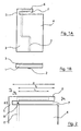
- FIGS. 1A and 1B which are respectively a top view and a view of side, illustrate a first embodiment of the invention.
- the antenna comprises a substrate plate 1 (not shown in FIG. 1), a supply line 2 and a conductive deposit 3.
- the supply line 2 is located on a first face (the lower face by example) of the substrate plate 1. This is for example a microstrip line.
- the conductive deposit 3, for example of copper, is located on a second face (the upper side for example) of the substrate plate 1 and can decompose (fictitiously, since it is in practice made in one piece) in three parts: a main surface 4, an intermediate part 5 and a radiating strand 6.
- the main surface 4 (rectangular in this example) of the conductive deposit 3 constitutes a ground plan for the supply line 2 located on the other side of the substrate plate 1.
- the antenna therefore generates symmetrical currents on the strand radiating 6.
- the antenna of the invention is autosymmetrized.
- the radiating strand 6 is rectangular and has a first end connected to the main surface 4 of the conductive deposit 3 by the intermediate part 5, and a second free end extending partially along one side of the surface main 4 of the driver depot 3.
- the length of the radiating strand 6 is close to ⁇ / 4, with ⁇ the wavelength the antenna.
- the antenna of the invention which is planar and whose maximum length is ⁇ / 4, has a smaller footprint than that of a dipole of length ⁇ / 2 or else than that of an inverted F antenna of length ⁇ / 4 but whose radiating strand is spaced a height h from the ground plane.
- the antenna of the invention not only has a very small footprint but also a large bandwidth. Indeed, the main surface 4 of the depot conductor 3 behaves like a ground plane, especially with respect to the line supply 2 and the coupling slot 7, and very little vis-à-vis the radiating strand 6, this which greatly reduces the selectivity of the antenna. In addition, the cavity effect (and therefore the antenna selectivity) is much less marked than for an inverted F antenna since the ground plane (that is to say the main surface 4 of the conductive deposit 3) and the radiating strand 6 are located in the same plane.
- the antenna according to the invention has a bandwidth of 20 to 30% and can be easily incorporated inside an ultra-light portable handset.
- the longitudinal space between the radiating strand 6 and the main surface 4 of the conductive deposit 3 forms a coupling slot 7 through which the supply line 2 supplies the radiating strand 6.
- the coupling slot 7 is also rectangular.
- FIG 2 is a partial detailed view of the antenna shown in Figure 1A.
- the antenna of the invention includes a serial stub and a parallel stub. These series and parallel stubs allow adaptation of the antenna according to the known principle of double stub adaptation, on a wide frequency band.
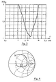
- FIG. 3 presents a variation curve, as a function of the frequency, of the standing wave ratio (or ROS) for an example of antenna according to the first mode of embodiment of FIGS. 1A and 2.
- This curve is used to calculate the bandwidth [f1, f2], defined here as the frequency band for which the ROS remains below 2.
- This bandwidth can also expressed as a percentage, obtained by dividing the width (f2, f1) of the bandwidth by the central frequency f3 of this band.
- the antenna according to the invention therefore has a bandwidth wide enough to simultaneously cover the transmission band and the transmission band reception.
- Figure 4 presents a variation curve, in a Smith chart, of the input impedance for the previous antenna example.
- the antenna is not, in this example, perfectly optimized. Indeed, better centering of the loop relative to the center of the abacus Smith would increase the performance of the antenna.
- the impedance of the power line carrying the HF signal to was set at 50 ⁇ , but this value does not constitute a characteristic decisive, because the input impedance of the antenna according to the invention can take any value between 10 and 200 ⁇ .
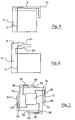
- FIG. 5 presents a top view of a second embodiment of the antenna according to the invention.
- This second embodiment differs from the first in that that the radiating strand 6 has an elbow 51 and extends along two sides of the main surface 4 of the conductive deposit 3.
- the overall size of the antenna is further reduced. If the length of radiating strand 6 is equal to ⁇ / 4, we can, by creating a elbow 51 at mid-length, reach dimensions close to ⁇ / 8. It is clear that the elbow 51 is not necessarily in the center of the radiating strand 6, or else that the radiating strand 6 may include more than one bend, so as to extend along more than two sides of the main surface 4.
- FIG. 6 presents a top view of a third embodiment of the antenna according to the invention.
- This third embodiment differs from the first in that the radiating strand 6 has a variable width over its length. This width variable, when chosen appropriately, increases bandwidth of the antenna.
- the radiating strand 6 has a recess 61, 62 on each of its longitudinal edges. It should be noted that in other embodiments, the radiating strand 6 may have a slit in the middle, or have several recesses on each of its longitudinal edges, or present one or more recesses on only one of its longitudinal edges.
- FIG. 7 shows a top view of a fourth embodiment of the antenna according to the invention.
- the antenna comprises several radiating strands 6 A , 6 B , 6 C , 6 D (four in this example).
- Each radiating strand 6 A , 6 B , 6 C , 6 D is connected to the main surface 4 by an intermediate part 5 A , 5 B , 5 C , 5 D , and each longitudinal space comprised between a radiating strand 6 A , 6 B , 6 C , 6 D and the main surface 4 forms a separate coupling slot 6 A , 6 B , 6 C , 6 D.
- the radiating strands 6 A , 6 B , 6 C , 6 D may or may not be identical.
- a single supply line can supply all the radiating strands 6 A , 6 B , 6 C , 6 D , or else several supply lines can be used.
- a single supply line can supply all the radiating strands 6 A , 6 B , 6 C , 6 D , or else several supply lines can be used.
- the antenna comprises means 71 for shaping the HF signals received from a main supply line (not shown) and to be transmitted on the various secondary supply lines 2 A , 2 B , 2 C , 2 D associated with the different radiating strands 6 A , 6 B , 6 C , 6 D.
- the elements (dividers, phase shifters) constituting the means 71 for shaping signals can be produced by different lengths of supply lines, by hybrid rings, or by any other solution known to those skilled in the art profession and performing the desired function.
- the antenna may for example include another ground plane, placed at a predetermined distance from the supply line and separated from it by air or by a dielectric.
- the antenna comprises the successive layers following: a ground plane, a dielectric, a supply line, a plate substrate and a conductive deposit.
- the role of the additional ground plane is for example remove stray radiation from the power line and obtain a radiation in half a space only.
- the additional ground plane is produced under form of a conductive deposit also comprising a main surface and a strand radiating associated with a slit. In this case, we obtain a symmetrical radiation of each side of the antenna.
- a strand radiating can have a variable width and extend on two sides of the surface main of the driver's depot.
- the invention also relates to any device for transmitting and / or receiving microwave signals equipped with an antenna according to the invention.
- Possibly, such device can comprise several antennas, and in particular a transmitting antenna and a receiving antenna.
Description
Le domaine de l'invention est celui des transmissions hertziennes. Plus précisément, l'invention concerne les antennes d'émission et/ou de réception, notamment pour les équipements de taille réduite, tels que les appareils portables.The field of the invention is that of radio transmissions. More specifically, the invention relates to transmit and / or receive antennas, in particular for smaller equipment, such as portable devices.
L'invention s'applique ainsi, en particulier, aux systèmes de radiocommunication avec des mobiles. En effet, l'extension des réseaux de radiocommunication avec des mobiles terrestres impose la mise au point de stations autonomes portables possédant la double fonctionnalité d'émission et de réception de signaux hyperfréquences. Ces stations doivent donc comprendre une antenne intégrée.The invention thus applies, in particular, to radiocommunication systems with mobiles. Indeed, the extension of radiocommunication networks with land mobile requires the development of portable autonomous stations having the dual functionality for transmitting and receiving microwave signals. These stations must therefore include an integrated antenna.
Les fréquences actuellement mises en oeuvre pour ces applications (de l'ordre de 2 GHz), ainsi que différentes contraintes liées à l'ergonomie et à l'esthétisme des combinés (intégration de l'antenne dans le dessin de l'appareil, facilité de stockage et d'utilisation, fragilité des antennes de grande taille, ...) conduisent à l'utilisation d'antennes de dimensions très réduites. On connaít ainsi plusieurs types d'antennes, dont les dimensions sont inférieures à la longueur d'onde du signal hyperfréquence.The frequencies currently used for these applications (of the order of 2 GHz), as well as various constraints linked to the ergonomics and aesthetics of combined (integration of the antenna in the design of the device, ease of storage and use, fragility of large antennas, ...) lead to use antennas of very reduced dimensions. We thus know several types of antennas, including the dimensions are less than the wavelength of the microwave signal.
Ces antennes se présentent en général sous la forme d'un élément rayonnant implanté à l'extérieur d'un boítier métallique, par exemple de forme parallélépipédique, constituant le blindage d'une ou plusieurs cartes électroniques assurant notamment des fonctions de modulation et de démodulation des signaux hyperfréquences, en émission et en réception respectivement.These antennas are generally in the form of a radiating element installed outside a metal case, for example of rectangular shape, constituting the shielding of one or more electronic cards ensuring in particular modulation and demodulation functions of microwave signals, in transmission and in reception respectively.
Un premier type d'antenne connu est le doublet demi-onde, c'est-à-dire un doublet de longueur λ/2, avec λ la longueur d'onde de fonctionnement.A first known type of antenna is the half-wave doublet, that is to say a doublet of length λ / 2, with λ the operating wavelength.
Le doublet demi-onde, qui est généralement constitué d'éléments de lignes bifilaires (c'est-à-dire de tiges cylindriques conductrices) alimentés par une ligne d'alimentation, présente des performances relativement large-bande, ce qui le rend utilisable dans de nombreuses applications.The half-wave doublet, which generally consists of line elements two-wire (i.e. conductive cylindrical rods) supplied by a line power supply, has relatively broadband performance, which makes it usable in many applications.
Toutefois, plusieurs inconvénients sont liés à son utilisation. En effet, les lignes d'alimentation (par exemple des lignes coaxiales) sont généralement dissymétriques, alors que les éléments rayonnants sont symétriques. Par conséquent, afin que le rayonnement du doublet demi-onde soit acceptable, il convient d'utiliser un symétriseur. Un symétriseur se présente traditionnellement comme un transformateur faisant intervenir des impédances localisées ou distribuées, et permettant, lorsqu'il est placé entre un élément rayonnant symétrique et une ligne d'alimentation dissymétrique, de rendre les courants symétriques sur la structure rayonnante. Un tel symétriseur présente l'inconvénient majeur de nécessiter une mise au point toujours délicate.However, several drawbacks are linked to its use. Indeed, the lines supply lines (for example coaxial lines) are generally asymmetrical, so that the radiating elements are symmetrical. Therefore, so that the radiation half-wave doublet is acceptable, a balun should be used. A balun traditionally presents itself as a transformer involving localized or distributed impedances, and allowing, when placed between an element radiating symmetrical and an asymmetrical power line, making the currents symmetrical on the radiating structure. Such a balun has the disadvantage major to require always a delicate development.
On connaít également des doublets demi-onde qui sont autosymétrisés, de façon à pouvoir être utilisés sans symétriseur. Toutefois, du fait de l'utilisation de tiges cylindriques conductrices, une telle caractéristique d'autosymétrie ne peut être obtenue qu'au prix d'une complexité accrue de la structure de l'antenne.We also know half-wave doublets which are self-symmetrized, so be able to be used without a balun. However, due to the use of rods conductive cylindrical, such an autosymmetry characteristic cannot be obtained that at the cost of increased complexity of the antenna structure.
Enfin, d'une façon générale, les doublets demi-onde à tiges cylindriques présentent un maniement mécanique difficile ainsi qu'un encombrement encore trop important (bien que réduit), la longueur minimale de l'antenne étant imposée par la longueur des brins principaux, soit environ λ/2.Finally, in general, the half-wave doublets with cylindrical rods have difficult mechanical handling and too much space important (although reduced), the minimum length of the antenna being imposed by the length of the main strands, about λ / 2.
Comme précisé auparavant, la réduction de l'encombrement est devenu un objectif essentiel pour les concepteurs d'antennes.As noted earlier, the reduction in footprint has become a essential objective for antenna designers.
Un second type d'antenne, encore plus compact que le doublet demi-onde, a donc été conçu. Il s'agit de l'antenne en F inversé, qui est constituée d'un élément conducteur rectangulaire horizontal et d'un élément conducteur rectangulaire vertical. L'élément vertical assure une fonction de court-circuit sur l'élément horizontal, en reliant l'une de ses extrémités à un plan de masse. La longueur de l'élément horizontal est généralement L = λ/4. En d'autres termes, l'élément horizontal est placé dans un plan parallèle au plan de masse et à une hauteur h de celui-ci.A second type of antenna, even more compact than the half-wave doublet, therefore has been designed. This is the inverted F antenna, which consists of a conductive element horizontal rectangular and a vertical rectangular conductive element. The element vertical ensures a short circuit function on the horizontal element, by connecting one of its ends to a ground plane. The length of the horizontal element is generally L = λ / 4. In other words, the horizontal element is placed in a plane parallel to the plane of mass and at a height h thereof.
Ainsi, pour des fréquences de l'ordre de 2 GHz, ces dimensions sont de l'ordre de quelques centimètres. L'antenne obtenue est donc d'encombrement très réduit (sa longueur minimale est λ/4 au lieu de λ/2 pour le doublet demi-onde).Thus, for frequencies of the order of 2 GHz, these dimensions are of the order a few centimeters. The antenna obtained is therefore very compact (its minimum length is λ / 4 instead of λ / 2 for the half-wave doublet).
En revanche, cette antenne présente des caractéristiques très dispersives en fréquence, et donc, en conséquence, une bande passante très faible, et par exemple de l'ordre de 2 à 3 %. Cela est dû au fait que cette structure d'antenne se comporte sensiblement comme un résonateur λ/4. However, this antenna has very dispersive characteristics in frequency, and therefore, consequently, a very low bandwidth, and for example of in the range of 2 to 3%. This is due to the fact that this antenna structure behaves much like a λ / 4 resonator.
La bande passante d'une antenne est ici définie comme la bande de fréquence sur laquelle le Rapport d'Onde Stationnaire (R.O.S) est inférieur à 2. Ce dernier paramètre représente l'aptitude de l'antenne à transmettre la puissance active qui lui est fournie, ce qui est le plus critique pour les antennes de taille réduite.The bandwidth of an antenna is here defined as the frequency band on which the Stationary Wave Ratio (R.O.S) is less than 2. This last parameter represents the ability of the antenna to transmit the active power supplied to it, this which is most critical for small antennas.
Cette grandeur est directement liée à l'impédance d'entrée de l'antenne, qui doit être adaptée à l'impédance de la ligne de transmission véhiculant le signal hyperfréquence à émettre et/ou à recevoir. Pour un fonctionnement optimal de l'antenne, il est nécessaire que cette impédance reste sensiblement constante (c'est-à-dire que le R.O.S reste inférieur à 2, un R.O.S. égal à 1 correspondant à une adaptation parfaite) sur un grande bande de fréquence. Une bande passante de 2 à 3 % telle qu'obtenue à l'aide d'une antenne en F inversée est généralement insuffisante.This quantity is directly related to the input impedance of the antenna, which must be adapted to the impedance of the transmission line carrying the microwave signal to send and / or receive. For optimal functioning of the antenna, it is necessary that this impedance remains substantially constant (i.e. the R.O.S remains lower at 2, an R.O.S. equal to 1 corresponding to a perfect adaptation) over a large band of frequency. A bandwidth of 2 to 3% as obtained using an F-antenna is generally insufficient.
Par ailleurs, le document US 4 825 220 décrit un élément rayonnant comprenant un dipôle intégré à une structure « balun ». Le plan de masse de la ligne de transmission micro ruban non équilibrée est divisé par une fente centrale de manière à former une ligne de transmission équilibrée agissant avec la fente située entre une partie des bras du dipôle formé. Le plan de masse est utilisé comme tel sur une partie de la ligne d'alimentation microruban.Furthermore, document US 4,825,220 describes a radiating element comprising a dipole integrated into a "balun" structure. The ground plane of the line of unbalanced micro ribbon transmission is divided by a central slot so as to form a balanced transmission line acting with the slot located between part of the arms of the dipole formed. The ground plane is used as such on a part of the microstrip supply line.
L'invention a notamment pour objectif de pallier les inconvénients des différents types connus d'antenne, et notamment ceux des doublets demi-onde et des antennes en F inversé.The invention particularly aims to overcome the drawbacks of the various known types of antenna, including those of half-wave dipoles and F-shaped antennas reversed.
Plus précisément, un objectif de l'invention est de fournir une antenne d'encombrement réduit présentant une large passante. Ainsi, l'invention a notamment pour objectif de fournir une telle antenne, dont la bande passante est au moins de l'ordre de 20 à 30 % et présentant un encombrement réduit notamment par rapport à une antenne en F inversé.More specifically, an objective of the invention is to provide an antenna small footprint with a large pass. Thus, the invention has in particular aims to provide such an antenna, whose bandwidth is at least of the order from 20 to 30% and having a reduced bulk especially in relation to an antenna in inverted F.
L'invention a également pour objectif de fournir une antenne autosymétrisée, et ne nécessitant donc aucun symétriseur.The invention also aims to provide a self-symmetrized antenna, and does not therefore requiring no balun.
L'invention a encore pour objectif de fournir une telle antenne, qui puisse fonctionner sur une grande plage d'impédances d'entrée, et en particulier pour des impédances d'entrée comprises entre 10 et 200 Ohms.The invention also aims to provide such an antenna, which can operate over a wide range of input impedances, and in particular for input impedances between 10 and 200 Ohms.
Ces objectifs, ainsi que d'autres qui apparaítront par la suite, sont atteints selon
l'invention à l'aide d'une antenne d'émission et/ou de réception de signaux
hyperfréquences décrite par la revendication 1. These objectives, as well as others that will appear later, are achieved according to
the invention using a signal transmitting and / or receiving antenna
The microwave described by
L'antenne de l'invention est donc réalisée en technologie imprimée, ce qui permet un gain de place considérable et un maintien mécanique beaucoup plus aisé.The antenna of the invention is therefore produced in printed technology, which allows considerable space savings and much easier mechanical maintenance.
Par ailleurs, la surface principale du dépôt conducteur, en constituant un plan de masse pour la ligne d'alimentation, assure que l'alimentation est autosymétrisée. En d'autres termes, l'antenne selon l'invention ne nécessite pas l'utilisation conjointe d'un symétriseur.Furthermore, the main surface of the conductive deposit, constituting a plane of ground for the supply line, ensures that the supply is autosymmetrized. In in other words, the antenna according to the invention does not require the joint use of a balun.
La ligne d'alimentation alimente le brin rayonnant par l'intermédiaire de la fente de couplage.The supply line feeds the radiating strand through the slit coupling.
L'antenne selon l'invention repose notamment sur une adaptation nouvelle et inventive de l'antenne en F inversé. En effet, la configuration bidimensionnelle de l'antenne en F inversé a été projetée dans un plan unique contenant toute l'antenne. En d'autres termes, le brin rayonnant et le plan de masse ne sont plus dans deux plans parallèles distincts, mais dans un même plan. Par rapport à l'antenne en F inversé, l'antenne de l'invention est donc beaucoup plus compacte puisque l'on s'affranchit de la hauteur h entre le brin rayonnant (ou élément conducteur horizontal) et le plan de masse.The antenna according to the invention is based in particular on a new adaptation and inventive of the inverted F antenna. Indeed, the two-dimensional configuration of the inverted F antenna was projected in a single plane containing the entire antenna. In in other words, the radiating strand and the ground plane are no longer in two planes separate parallels, but in the same plane. Compared to the inverted F antenna, the antenna of the invention is therefore much more compact since it overcomes the height h between the radiating strand (or horizontal conducting element) and the ground plane.
De plus, l'antenne de l'invention possède une bande passante beaucoup plus large que celle d'une antenne en F inversé. Ceci s'explique en particulier par le fait que pour l'antenne en F inversé, le brin rayonnant est situé juste au dessus du plan de masse et forme avec celui-ci une cavité qui est très sélective en fréquence (généralement 2 à 3 % de bande passante). Par contre, dans le cas de l'invention, le plan de masse et le brin rayonnant sont situés dans un même plan, de sorte que l'effet de cavité est beaucoup moins marqué. Ceci permet d'atteindre des largeurs de bande proches de 25 %, et de couvrir simultanément la bande d'émission et la bande de réception.In addition, the antenna of the invention has a much wider bandwidth than that of an inverted F antenna. This is explained in particular by the fact that for the inverted F antenna, the radiating strand is located just above the ground plane and forms with this a cavity which is very selective in frequency (generally 2 to 3% of bandwidth). On the other hand, in the case of the invention, the ground plane and the strand radiating are located in the same plane, so the cavity effect is much less marked. This achieves bandwidths close to 25%, and simultaneously cover the transmit band and the receive band.
Avantageusement, ladite ligne d'alimentation et ladite fente de couplage se croisent en un point appelé point de croisement, ladite ligne d'alimentation présentant une portion d'extrémité, ou stub série, s'étendant au-delà dudit point de croisement d'une première longueur adaptable, et ladite fente de couplage présentant une portion d'extrémité, ou stub parallèle, s'étendant au-delà dudit point de croisement d'une seconde longueur adaptable.Advantageously, said supply line and said coupling slot are cross at a point called cross point, said supply line having a end portion, or series stub, extending beyond said crossing point of a first adaptable length, and said coupling slot having a portion end, or parallel stub, extending beyond said crossing point by one second adaptable length.
Ainsi, il est possible de mettre en oeuvre le principe connu de l'adaptation double stubs (série et parallèle). Un choix convenable de ces stubs série et parallèle, et éventuellement d'autres paramètres (largeur du brin rayonnant, largeur de la fente de couplage, épaisseur de la partie de liaison de dépôt conducteur reliant le brin rayonnant à la surface principale, position de la ligne d'alimentation par rapport à la partie de liaison de dépôt conducteur) permet d'adapter l'antenne sur une large bande passante.Thus, it is possible to implement the known principle of double adaptation stubs (series and parallel). A suitable choice of these series and parallel stubs, and possibly other parameters (width of the radiating strand, width of the slit coupling, thickness of the conductive deposition link part connecting the radiating strand to the main surface, position of the supply line in relation to the connecting part conductive deposition) allows the antenna to be adapted over a wide bandwidth.
Préférentiellement, au moins un des éléments appartenant au groupe comprenant ledit brin rayonnant, ladite surface principale, et ladite fente de couplage, est de forme sensiblement rectangulaire.Preferably, at least one of the elements belonging to the group comprising said radiating strand, said main surface, and said coupling slot, is shaped substantially rectangular.
De façon avantageuse, ledit dépôt conducteur comprend au moins deux brins rayonnants, l'espace longitudinal compris entre chacun desdits brins rayonnants et ladite surface principale formant une fente de couplage distincte.Advantageously, said conductive deposit comprises at least two strands radiant, the longitudinal space between each of said radiating strands and said main surface forming a separate coupling slot.
Ainsi, on peut obtenir :
- une diversité de polarisation, en associant la ligne d'alimentation à un diviseur;
- une polarisation circulaire, en associant la ligne d'alimentation à des diviseurs et des déphaseurs.
- a diversity of polarization, by associating the supply line with a divider;
- circular polarization, by associating the supply line with dividers and phase shifters.
Avantageusement, l'antenne comprend au moins deux lignes d'alimentation, chacun desdits brins rayonnants coopérant avec une desdites lignes d'alimentation.Advantageously, the antenna comprises at least two feed lines, each of said radiating strands cooperating with one of said supply lines.
De cette façon, on peut obtenir une antenne multibande duplexée.In this way, a duplex multiband antenna can be obtained.
Préférentiellement, ledit brin rayonnant présente au moins un coude, de façon que ledit brin rayonnant s'étende au moins partiellement le long d'au moins deux côtés de ladite surface principale.Preferably, said radiating strand has at least one bend, so that said radiating strand extends at least partially along at least two sides of said main surface.
De cette façon, on limite l'encombrement global de l'antenne puisque la dimension minimale de l'antenne n'est plus liée à la longueur totale brin rayonnant mais seulement à la longueur des côtés de la surface principale du dépôt conducteur.In this way, the overall size of the antenna is limited since the minimum antenna dimension is no longer linked to the total length of the radiating strand but only along the sides of the main surface of the conductive deposit.
De façon préférentielle, ledit brin rayonnant présente une largeur variable. Ainsi, on augmente la bande passante de l'antenne.Preferably, said radiating strand has a variable width. So, the bandwidth of the antenna is increased.
Avantageusement, ledit brin rayonnant présente au moins un décrochement sur au moins un des bords longitudinaux et/ou au moins une lumière sur sa surface. La lumière sur la surface du brin rayonnant est par exemple une fente.Advantageously, said radiating strand exhibits at least one offset on the at least one of the longitudinal edges and / or at least one light on its surface. The light on the surface of the radiating strand is for example a slot.
Dans un mode de réalisation avantageux de l'invention, l'antenne comprend également un plan de masse placé à une distance prédéterminée de ladite ligne d'alimentation.In an advantageous embodiment of the invention, the antenna comprises also a ground plane placed at a predetermined distance from said line Power.
Si le plan de masse est sans élément rayonnant, il permet de supprimer le rayonnement parasite de la ligne d'alimentation et d'obtenir un rayonnement dans un demi-espace uniquementIf the ground plane is without radiating element, it makes it possible to remove the stray radiation from the power line and get radiation in a half space only
Selon une variante avantageuse, ledit plan de masse est un dépôt conducteur de même forme que celui situé sur la seconde face de ladite plaque de substrat, comprenant une surface principale et au moins un brin rayonnant.According to an advantageous variant, said ground plane is a conductive deposit of same shape as that located on the second face of said substrate plate, comprising a main surface and at least one radiating strand.
Dans ce cas, le plan de masse permet d'obtenir un rayonnement symétrique de chaque côté de l'antenne.In this case, the ground plane makes it possible to obtain a symmetrical radiation of each side of the antenna.
Préférentiellement, ladite ligne d'alimentation présente une impédance sensiblement comprise entre 10 Ohms et 200 Ohms.Preferably, said supply line has an impedance substantially between 10 Ohms and 200 Ohms.
De façon avantageuse, la longueur dudit brin rayonnant est sensiblement comprise entre λ/8 et λ/4, λ étant la longueur d'onde desdits signaux hyperfréquences.Advantageously, the length of said radiating strand is substantially understood between λ / 8 and λ / 4, λ being the wavelength of said microwave signals.
L'invention concerne également un dispositif d'émission et/ou de réception de signaux hyperfréquences, comprenant au moins une antenne telle que décrite ci-dessus.The invention also relates to a device for transmitting and / or receiving microwave signals, comprising at least one antenna as described above.
D'autres caractéristiques et avantages de l'invention apparaítront à la lecture de la description suivante de plusieurs modes de réalisation préférentiels de l'invention, donnés à titre d'exemple indicatif et non limitatif, et des dessins annexés, dans lesquels :
- les figures 1A et 1B présentent chacune une vue, respectivement de dessus et de côté, d'un premier mode de réalisation d'une antenne selon l'invention ;
- la figure 2 est une vue détaillée partielle de l'antenne présentée sur la figure 1A ;
- la figure 3 présente une courbe de variation, en fonction de la fréquence, du rapport d'onde stationnaire pour un exemple d'antenne selon l'invention ;
- la figure 4 est un diagramme de Smith présentant la courbe d'impédance correspondant à un exemple d'antenne selon l'invention ;
- les figures 5, 6
et 7 présentent chacune une vue de dessus d'un mode de réalisation distinct (second, troisième et quatrième respectivement) d'une antenne selon l'invention.
- FIGS. 1A and 1B each show a view, respectively from above and from the side, of a first embodiment of an antenna according to the invention;
- Figure 2 is a partial detailed view of the antenna shown in Figure 1A;
- FIG. 3 shows a variation curve, as a function of frequency, of the standing wave ratio for an example antenna according to the invention;
- FIG. 4 is a Smith diagram showing the impedance curve corresponding to an example of antenna according to the invention;
- Figures 5, 6 and 7 each show a top view of a separate embodiment (second, third and fourth respectively) of an antenna according to the invention.
L'invention concerne donc une antenne de taille réduite à large bande passante. Cette antenne est notamment destinée à équiper des appareils portables, et par exemple des émetteurs/récepteurs de réseaux de radiocommunication avec des mobiles terrestres.The invention therefore relates to a reduced-size antenna with wide bandwidth. This antenna is in particular intended to equip portable devices, and for example transmitters / receivers of radiocommunication networks with land mobiles.
Les figures 1A et 1B, qui sont respectivement une vue de dessus et une vue de côté, illustrent un premier mode de réalisation de l'invention.FIGS. 1A and 1B, which are respectively a top view and a view of side, illustrate a first embodiment of the invention.
Dans ce mode de réalisation, l'antenne comprend une plaque de substrat 1 (non
représentée sur la figure 1), une ligne d'alimentation 2 et un dépôt conducteur 3.In this embodiment, the antenna comprises a substrate plate 1 (not
shown in FIG. 1), a
La plaque de substrat 1 est par exemple un substrat faible perte Duroïd du type
verre téflon présentant une permittivité relative εr = 2,2 et une épaisseur réduite de 0,76
mm.The
La ligne d'alimentation 2 est située sur une première face (la face inférieure par
exemple) de la plaque de substrat 1. Il s'agit par exemple d'une ligne microruban.The
Le dépôt conducteur 3, par exemple de cuivre, est situé sur une seconde face (la
face supérieure par exemple) de la plaque de substrat 1 et peut se décomposer
(fictivement, puisqu'il est en pratique réalisé d'une seule pièce) en trois parties : une
surface principale 4, une partie intermédiaire 5 et un brin rayonnant 6.The
La surface principale 4 (rectangulaire dans cet exemple) du dépôt conducteur 3
constitue un plan de masse pour la ligne d'alimentation 2 située sur l'autre face de la
plaque de substrat 1. L'antenne génère donc des courants symétriques sur le brin
rayonnant 6. En d'autres termes, l'antenne de l'invention est autosymétrisée.The main surface 4 (rectangular in this example) of the
Dans cet exemple, le brin rayonnant 6 est rectangulaire et possède une première
extrémité reliée à la surface principale 4 du dépôt conducteur 3 par la partie intermédiaire
5, et une seconde extrémité libre s'étendant partiellement le long d'un côté de la surface
principale 4 du dépôt conducteur 3.In this example, the radiating
La longueur du brin rayonnant 6 est proche de λ / 4, avec λ la longueur d'onde
de fonctionnement de l'antenne.The length of the
Ainsi, l'antenne de l'invention, qui est plane et dont la longueur maximale est λ/4, présente un encombrement plus faible que celui d'un dipôle de longueur λ/2 ou encore que celui d'une antenne en F inversé de longueur λ /4 mais dont le brin rayonnant est espacé d'une hauteur h du plan de masse.Thus, the antenna of the invention, which is planar and whose maximum length is λ / 4, has a smaller footprint than that of a dipole of length λ / 2 or else than that of an inverted F antenna of length λ / 4 but whose radiating strand is spaced a height h from the ground plane.
L'antenne de l'invention présente non seulement un très faible encombrement
mais également une large bande passante. En effet, la surface principale 4 du dépôt
conducteur 3 se comporte comme un plan de masse surtout vis-à-vis de la ligne
d'alimentation 2 et de la fente de couplage 7, et très peu vis-à-vis du brin rayonnant 6, ce
qui diminue fortement la sélectivité de l'antenne. De plus, l'effet de cavité (et donc la
sélectivité de l'antenne) est beaucoup moins marqué que pour une antenne en F inversé
puisque le plan de masse (c'est-à-dire la surface principale 4 du dépôt conducteur 3) et le
brin rayonnant 6 sont situés dans un même plan.The antenna of the invention not only has a very small footprint
but also a large bandwidth. Indeed, the
D'une façon générale, l'antenne selon l'invention présente une bande passante de 20 à 30 % et peut être aisément incorporée à l'intérieur d'un combiné portable ultra-léger.In general, the antenna according to the invention has a bandwidth of 20 to 30% and can be easily incorporated inside an ultra-light portable handset.
L'espace longitudinal compris entre le brin rayonnant 6 et la surface principale 4
du dépôt conducteur 3 forme une fente de couplage 7 par l'intermédiaire de laquelle la
ligne d'alimentation 2 alimente le brin rayonnant 6.The longitudinal space between the radiating
Dans l'exemple présenté sur la figure 1A, la fente de couplage 7 est également
rectangulaire.In the example shown in FIG. 1A, the
La figure 2 est une vue détaillée partielle de l'antenne présentée sur la figure 1A.Figure 2 is a partial detailed view of the antenna shown in Figure 1A.
Afin de mettre au point l'antenne et d'ajuster sa largeur de bande en particulier, plusieurs paramètres peuvent être modifiés, et notamment :
- la longueur l1 d'un stub série, le stub série étant la portion d'extrémité de la ligne d'alimentation 2 qui dépasse du point de croisement 9 entre la ligne d'alimentation 2 et la fente de couplage 7 ;
- la longueur l2 d'un stub parallèle, le stub parallèle étant la portion d'extrémité de la fente de couplage 7 qui dépasse du point de croisement 9 ;
- la largeur e1 du brin rayonnant 6 ;
- la profondeur p de la fente de couplage 7 ;
- la largeur g de la fente de couplage 7 ;
- l'épaisseur e2 de la partie intermédiaire 5 reliant le brin rayonnant 6 la surface principale 4 ;
- la distance ep entre la ligne d'alimentation 2 et la partie intermédiaire 5.
- the length l 1 of a series stub, the series stub being the end portion of the
supply line 2 which protrudes from the crossing point 9 between thesupply line 2 and thecoupling slot 7; - the length l 2 of a parallel stub, the parallel stub being the end portion of the
coupling slot 7 which protrudes from the crossing point 9; - the width e 1 of the
radiating strand 6; - the depth p of the
coupling slot 7; - the width g of the
coupling slot 7; - the thickness e 2 of the
intermediate part 5 connecting theradiating strand 6 to themain surface 4; - the distance e p between the
supply line 2 and theintermediate part 5.
Ainsi, bien que réalisée en technologie imprimée, l'antenne de l'invention comprend un stub série et un stub parallèle. Ces stubs série et parallèle permettent l'adaptation de l'antenne selon le principe connu de l'adaptation double stub, sur une large bande de fréquences.Thus, although produced in printed technology, the antenna of the invention includes a serial stub and a parallel stub. These series and parallel stubs allow adaptation of the antenna according to the known principle of double stub adaptation, on a wide frequency band.
La figure 3 présente une courbe de variation, en fonction de la fréquence, du rapport d'onde stationnaire (ou ROS) pour un exemple d'antenne selon le premier mode de réalisation des figures 1A et 2.FIG. 3 presents a variation curve, as a function of the frequency, of the standing wave ratio (or ROS) for an example of antenna according to the first mode of embodiment of FIGS. 1A and 2.
Dans cet exemple, les paramètres de l'antenne possèdent les valeurs suivantes :
- l1 = 13 mm ;
- l2 = 22,6 mm ;
- e1 = 5 mm ;
- e2 = 6 mm ;
- g = 5 mm ;
- ep = 1,65 mm ;
- p = 24,25 mm.
- l 1 = 13 mm;
- l 2 = 22.6 mm;
- e 1 = 5 mm;
- e 2 = 6 mm;
- g = 5 mm;
- e p = 1.65 mm;
- p = 24.25 mm.
Cette courbe permet de calculer la bande passante [f1, f2], définie ici comme la bande de fréquences pour laquelle le ROS reste inférieur à 2. Cette bande passante peut également s'exprimer en pourcentage, obtenu par division de la largeur (f2, f1) de la bande passante par la fréquence centrale f3 de cette bande.This curve is used to calculate the bandwidth [f1, f2], defined here as the frequency band for which the ROS remains below 2. This bandwidth can also expressed as a percentage, obtained by dividing the width (f2, f1) of the bandwidth by the central frequency f3 of this band.
Dans l'exemple précité, la bande passante est sensiblement comprise entre f1 = 1,823 GHz et f2 = 2,333 GHz.In the above example, the bandwidth is substantially between f1 = 1.823 GHz and f2 = 2.333 GHz.
Avec une fréquence centrale f3 = 2,078 GHz, cette bande passante est environ égale à 25 %. L'antenne selon l'invention possède donc une bande passante suffisamment large pour couvrir simultanément la bande d'émission et la bande de réception.With a center frequency f3 = 2.078 GHz, this bandwidth is approximately equal to 25%. The antenna according to the invention therefore has a bandwidth wide enough to simultaneously cover the transmission band and the transmission band reception.
La figure 4 présente une courbe de variation, dans un abaque de Smith, de l'impédance d'entrée pour l'exemple précédent d'antenne. On rapelle que s'il existe une boucle autour du centre de l'abaque (qui est le point d'adaptation parfaite par rapport à une ligne d'alimentation 50 Ω), ceci garantit une faible dispersion en fréquence et traduit l'efficacité de l'adaptation.Figure 4 presents a variation curve, in a Smith chart, of the input impedance for the previous antenna example. Remember that if there is a loop around the center of the abacus (which is the point of perfect adaptation with respect to 50 Ω power line), this guarantees low frequency dispersion and reflects the effectiveness of adaptation.
Il est à noter toutefois que l'antenne n'est pas, dans cet exemple, parfaitement optimisée. En effet, un meilleur centrage de la boucle par rapport au centre de l'abaque de Smith permettrait d'accroítre les performances de l'antenne.It should be noted however that the antenna is not, in this example, perfectly optimized. Indeed, better centering of the loop relative to the center of the abacus Smith would increase the performance of the antenna.
Dans cet exemple, l'impédance de la ligne d'alimentation véhiculant le signal HF à émettre a été fixée à 50 Ω, mais cette valeur ne constitue pas une caractéristique déterminante, car l'impédance d'entrée de l'antenne selon l'invention peut prendre n'importe quelle valeur comprise entre 10 et 200 Ω.In this example, the impedance of the power line carrying the HF signal to was set at 50 Ω, but this value does not constitute a characteristic decisive, because the input impedance of the antenna according to the invention can take any value between 10 and 200 Ω.
La figure 5 présente une vue de dessus d'un second mode de réalisation de
l'antenne selon l'invention. Ce second mode de réalisation se différencie du premier en ce
que le brin rayonnant 6 comporte un coude 51 et s'étend le long de deux côtés de la
surface principale 4 du dépôt conducteur 3. Ainsi, l'encombrement global de l'antenne est
encore réduit. Si la longueur de brin rayonnant 6 est égale à λ/4, on peut, en créant un
coude 51 à mi-longueur, atteindre des dimensions proches de λ/8. Il est clair que le coude
51 n'est pas forcément au centre du brin rayonnant 6, ou encore que le brin rayonnant 6
peut comprendre plus d'un coude, de façon à s'étendre le long de plus de deux côtés de la
surface principale 4.FIG. 5 presents a top view of a second embodiment of
the antenna according to the invention. This second embodiment differs from the first in that
that the
La figure 6 présente une vue de dessus d'un troisième mode de réalisation de
l'antenne selon l'invention. Ce troisième mode de réalisation se différencie du premier en
ce que le brin rayonnant 6 possède une largeur variable sur sa longueur. Cette largeur
variable, lorsqu'elle est choisie convenablement, permet d'augmenter la bande passante
de l'antenne. Dans l'exemple présenté sur la figure 6, le brin rayonnant 6 présente un
décrochement 61, 62 sur chacun de ses bords longitudinaux. Il est à noter que dans
d'autres modes de réalisation, le brin rayonnant 6 peut présenter une fente en son milieu,
ou présenter plusieurs décrochements sur chacun de ses bords longitudinaux, ou encore
présenter un ou plusieurs décrochements sur un seul de ses bords longitudinaux.FIG. 6 presents a top view of a third embodiment of
the antenna according to the invention. This third embodiment differs from the first in
that the
La figure 7 présente une vue de dessus d'un quatrième mode de réalisation de
l'antenne selon l'invention. Dans ce quatrième mode de réalisation, l'antenne comporte
plusieurs brins rayonnants 6A, 6B, 6C, 6D (quatre dans cet exemple). Chaque brin
rayonnant 6A, 6B, 6C, 6D est relié à la surface principale 4 par une partie intermédiaire 5A,
5B, 5C, 5D, et chaque espace longitudinal compris entre un brin rayonnant 6A, 6B, 6C, 6D
et la surface principale 4 forme une fente de couplage distincte 6A, 6B, 6C, 6D.Figure 7 shows a top view of a fourth embodiment of the antenna according to the invention. In this fourth embodiment, the antenna comprises several radiating
Selon les applications, les brins rayonnants 6A, 6B, 6C, 6D peuvent être identiques
ou non.Depending on the applications, the radiating
De même, une ligne d'alimentation unique peut alimenter tous les brins
rayonnants 6A, 6B, 6C, 6D, ou bien plusieurs lignes d'alimentation peuvent être utilisées.
Ainsi, en accroissant le nombre de lignes d'alimentation et en associant chacun des brins
rayonnant à une ligne d'alimentation distincte, on peut obtenir une antenne multibande
duplexée.Likewise, a single supply line can supply all the radiating
Dans l'exemple présenté sur la figure 7,, l'antenne comprend des moyens 71 de
mise en forme des signaux HF reçus d'une ligne d'alimentation principale (non
représentée) et devant être transmis sur les différentes lignes d'alimentation secondaires
2A, 2B, 2C, 2D associées aux différents brins rayonnants 6A, 6B, 6C, 6D.In the example presented in FIG. 7, the antenna comprises means 71 for shaping the HF signals received from a main supply line (not shown) and to be transmitted on the various
Ces moyens 71 permettent d'obtenir :
- soit de la diversité de polarisation linéaire, si les moyens 71 comprennent un diviseur ;
- soit de la polarisation circulaire, si les moyens 71 comprennent des diviseurs et des déphaseurs.
- either of the linear polarization diversity, if the means 71 comprise a divider;
- or circular polarization, if the means 71 comprise dividers and phase shifters.
Les éléments (diviseurs, déphaseurs) constituant les moyens 71 de mise en forme
des signaux peuvent être réalisés par des longueurs de lignes d'alimentation différentes,
par des anneaux hybrides, ou encore par toute autre solution connue de l'homme du
métier et réalisant la fonction désirée.The elements (dividers, phase shifters) constituting the
Il est clair que de nombreux autres modes de réalisation de l'invention peuvent être envisagés. L'antenne peut par exemple comprendre un autre plan de masse, placé à une distance prédéterminée de la ligne d'alimentation et séparé de celle-ci par de l'air ou par un diélectrique. Dans ce dernier cas, l'antenne comprend les couches successives suivantes : un plan de masse, un diélectrique, une ligne d'alimentation, une plaque de substrat et un dépôt conducteur. Le rôle du plan de masse supplémentaire est par exemple de supprimer le rayonnement parasite de la ligne d'alimentation et d'obtenir un rayonnement dans un demi-espace uniquement.It is clear that many other embodiments of the invention can be considered. The antenna may for example include another ground plane, placed at a predetermined distance from the supply line and separated from it by air or by a dielectric. In the latter case, the antenna comprises the successive layers following: a ground plane, a dielectric, a supply line, a plate substrate and a conductive deposit. The role of the additional ground plane is for example remove stray radiation from the power line and obtain a radiation in half a space only.
On peut également prévoir que le plan de masse supplémentaire soit réalisé sous forme d'un dépôt conducteur comprenant également une surface principale et un brin rayonnant associé à une fente. Dans ce cas, on obtient un rayonnement symétrique de chaque côté de l'antenne.It can also be provided that the additional ground plane is produced under form of a conductive deposit also comprising a main surface and a strand radiating associated with a slit. In this case, we obtain a symmetrical radiation of each side of the antenna.
Les caractéristiques des différents modes de réalisation présentés ci-dessus peuvent également être combinées de multiples façons, afin de fournir encore d'autres modes de réalisation de l'antenne de l'invention. Ainsi, à titre d'exemple, un brin rayonnant peut présenter une largeur variable et s'étendre sur deux côtés de la surface principale du dépôt conducteur.The characteristics of the various embodiments presented above can also be combined in multiple ways to provide even more embodiments of the antenna of the invention. So, for example, a strand radiating can have a variable width and extend on two sides of the surface main of the driver's depot.
L'invention concerne également tout dispositif d'émission et/ou de réception de signaux hyperfréquences équipé d'une antenne selon l'invention. Eventuellement, un tel dispositif peut comprendre plusieurs antennes, et en particulier une antenne d'émission et une antenne de réception.The invention also relates to any device for transmitting and / or receiving microwave signals equipped with an antenna according to the invention. Possibly, such device can comprise several antennas, and in particular a transmitting antenna and a receiving antenna.
Claims (13)
- Transmitting and/or receiving antenna for microwave signals, comprising:a substrate plate (1);at least one feeder (2; 2A to 2D) located on a first face of said substrate plate;a conductive deposition (3) deposited on a second face, opposite to said first face of said substrate plate (1) so as to define:a principal surface (4) forming the ground plane for said feeder (2; 2A to 2D);at least one radiating strand (6; 6A to 6D) comprising a first end connected to said principal surface (4) and a second free end extending at least partially along at least one side of said principal surface (4);characterised in that a longitudinal space between each of said radiating strands (6; 6A to 6D) and said principal surface (4) forms a coupling slot (7; 7A to 7D) with one feeder.
- Antenna according to Claim 1, characterised in that said feeder (2; 2A to 2D) and said coupling slot (7; 7A to 7D) intersect at a point termed the crosspoint,
in that said feeder(2; 2A to 2D) has an end portion, or series stub, extending beyond said crosspoint, of a first adaptable length,
and in that said coupling slot (7; 7A to 7D) has an end portion, or parallel stub, extending beyond said crosspoint, of a second adaptable length. - Antenna according to any of Claims 1 and 2,
characterised in that at least one of the elements belonging to a group comprising said radiating strand (6; 6A to 6D), said principal surface (4), and said coupling slot (7; 7A to 7D), is of a substantially rectangular shape. - Antenna according to any of Claims 1 to 3, characterised in that said conductive deposition (3) comprises at least two radiating strands (6A to 6D), the longitudinal space between each of said radiating strands and said principal surface forming a distinct coupling slot (7A to 7D).
- Antenna according to Claim 4, characterised in that it comprises at least two feeders (2A to 2D), each of said radiating strands (6A to 6D) co-operating with one of said feeders.
- Antenna according to any of Claims 1 to 5, characterised in that said radiating strand (6; 6A to 6D) has at least one elbow (51), so that said radiating strand extends at least partially along at least two sides of said principal surface (41).
- Antenna according to any of Claims 1 to 6, characterised in that said radiating strand (6; 6A to 6D) has a variable length.
- Antenna according to Claim 7, characterised in that said radiating strand (6; 6A to 6D) has at least one offset (61, 62) on at least one of the longitudinal edges and/or at least one opening, for example a slot, on its surface.
- Antenna according to any of Claims 1 to 8, characterised in that it also comprises a supplementary ground plane superimposed at a predetermined distance from said feeder, said supplementary ground plane not forming any radiating element and allowing a radiation from the antenna to be obtained in a unique semi-space.
- Antenna according to any of Claims 1 to 8, characterised in that it also comprises a supplementary ground plane superimposed at a predetermined distance from said feeder, said supplementary ground plane being a conductive deposition of the same shape as that situated on the second face of said substrate plate, comprising a principal surface and at least one radiating strand, said supplementary ground plane allowing a radiation from the antenna to be obtained that is symmetrical on each side of the antenna.
- Antenna according to any of Claims 1 to 10,
characterised in that said feeder (2; 2A to 2D) has an input impedance that is substantially between 10 Ohms and 200 Ohms. - Antenna according to any of Claims 1 to 11,
characterised in that the length of said radiating strand (6; 6A to 6D) is substantially between _/8 and _/4, _ being the wavelength of said microwave signals. - Transmitting and/or receiving device for microwave signals, characterised in that it comprises at least one antenna according to any of Claims 1 to 12.
Applications Claiming Priority (2)
| Application Number | Priority Date | Filing Date | Title |
|---|---|---|---|
| FR9414198 | 1994-11-22 | ||
| FR9414198A FR2727250A1 (en) | 1994-11-22 | 1994-11-22 | MONOPOLY BROADBAND ANTENNA IN UNIPLANAR PRINTED TECHNOLOGY AND TRANSMITTING AND / OR RECEIVING DEVICE INCORPORATING SUCH ANTENNA |
Publications (2)
| Publication Number | Publication Date |
|---|---|
| EP0714151A1 EP0714151A1 (en) | 1996-05-29 |
| EP0714151B1 true EP0714151B1 (en) | 2003-09-03 |
Family
ID=9469188
Family Applications (1)
| Application Number | Title | Priority Date | Filing Date |
|---|---|---|---|
| EP95460040A Expired - Lifetime EP0714151B1 (en) | 1994-11-22 | 1995-11-06 | Broadband monopole antenna in uniplanar printed circuit technology and transmit- and/or receive device with such an antenna |
Country Status (5)
| Country | Link |
|---|---|
| US (1) | US5835063A (en) |
| EP (1) | EP0714151B1 (en) |
| JP (1) | JPH08256009A (en) |
| DE (1) | DE69531655T2 (en) |
| FR (1) | FR2727250A1 (en) |
Families Citing this family (48)
| Publication number | Priority date | Publication date | Assignee | Title |
|---|---|---|---|---|
| US6138050A (en) * | 1997-09-17 | 2000-10-24 | Logitech, Inc. | Antenna system and apparatus for radio-frequency wireless keyboard |
| US5929813A (en) * | 1998-01-09 | 1999-07-27 | Nokia Mobile Phones Limited | Antenna for mobile communications device |
| EP0929115A1 (en) * | 1998-01-09 | 1999-07-14 | Nokia Mobile Phones Ltd. | Antenna for mobile communications device |
| US6016126A (en) * | 1998-05-29 | 2000-01-18 | Ericsson Inc. | Non-protruding dual-band antenna for communications device |
| AU2979700A (en) * | 1999-02-02 | 2000-08-25 | Qualcomm Incorporated | Wireless phone design for improving radiation performance |
| US6140970A (en) * | 1999-04-30 | 2000-10-31 | Nokia Mobile Phones Limited | Radio antenna |
| US6414640B1 (en) * | 2000-04-18 | 2002-07-02 | Nokia Corporation | Antenna assembly, and associated method, which exhibits circular polarization |
| FR2811478A1 (en) * | 2000-07-05 | 2002-01-11 | Eaton Corp | Planar antenna has gamma feed by plated through hole is all printed construction |
| JP3830358B2 (en) * | 2001-03-23 | 2006-10-04 | 日立電線株式会社 | Flat antenna and electric device having the same |
| US6456243B1 (en) | 2001-06-26 | 2002-09-24 | Ethertronics, Inc. | Multi frequency magnetic dipole antenna structures and methods of reusing the volume of an antenna |
| JP3622959B2 (en) * | 2001-11-09 | 2005-02-23 | 日立電線株式会社 | Manufacturing method of flat antenna |
| KR100454103B1 (en) * | 2002-01-30 | 2004-10-26 | 주식회사 선우커뮤니케이션 | The asymmetrical flat type dipole antenna with broadband characteristics and dipole antenna array structure using the same elements |
| US6573867B1 (en) | 2002-02-15 | 2003-06-03 | Ethertronics, Inc. | Small embedded multi frequency antenna for portable wireless communications |
| JP3656610B2 (en) * | 2002-03-27 | 2005-06-08 | 日立電線株式会社 | Plate-like antenna and electric device having the same |
| US6943730B2 (en) * | 2002-04-25 | 2005-09-13 | Ethertronics Inc. | Low-profile, multi-frequency, multi-band, capacitively loaded magnetic dipole antenna |
| US6744410B2 (en) * | 2002-05-31 | 2004-06-01 | Ethertronics, Inc. | Multi-band, low-profile, capacitively loaded antennas with integrated filters |
| GB0210601D0 (en) * | 2002-05-09 | 2002-06-19 | Koninkl Philips Electronics Nv | Antenna arrangement and module including the arrangement |
| JP3690375B2 (en) | 2002-07-09 | 2005-08-31 | 日立電線株式会社 | Plate-like multi-antenna and electric device provided with the same |
| US6911940B2 (en) * | 2002-11-18 | 2005-06-28 | Ethertronics, Inc. | Multi-band reconfigurable capacitively loaded magnetic dipole |
| US6859175B2 (en) | 2002-12-03 | 2005-02-22 | Ethertronics, Inc. | Multiple frequency antennas with reduced space and relative assembly |
| US7084813B2 (en) * | 2002-12-17 | 2006-08-01 | Ethertronics, Inc. | Antennas with reduced space and improved performance |
| JP2004208223A (en) * | 2002-12-26 | 2004-07-22 | Alps Electric Co Ltd | Two band patch antenna |
| TW574767B (en) | 2003-01-13 | 2004-02-01 | Uniwill Comp Corp | Antenna and shield assembly and wireless transmission module thereof |
| US6919857B2 (en) * | 2003-01-27 | 2005-07-19 | Ethertronics, Inc. | Differential mode capacitively loaded magnetic dipole antenna |
| US7123209B1 (en) | 2003-02-26 | 2006-10-17 | Ethertronics, Inc. | Low-profile, multi-frequency, differential antenna structures |
| JP2004343402A (en) * | 2003-05-15 | 2004-12-02 | Nippon Antenna Co Ltd | Antenna system |
| KR100544675B1 (en) * | 2003-10-18 | 2006-01-23 | 한국전자통신연구원 | Apparatus for Repeating Satellite Signal using Microstrip Patch Array Antenna |
| KR100594964B1 (en) * | 2003-12-24 | 2006-06-30 | 한국전자통신연구원 | Broadband Inverted L Antenna with Fixed Polarization |
| JP4213634B2 (en) | 2004-06-24 | 2009-01-21 | インターナショナル・ビジネス・マシーンズ・コーポレーション | Mobile information terminal with communication function |
| US7432860B2 (en) * | 2006-05-17 | 2008-10-07 | Sony Ericsson Mobile Communications Ab | Multi-band antenna for GSM, UMTS, and WiFi applications |
| US9317798B2 (en) * | 2007-08-29 | 2016-04-19 | Intelleflex Corporation | Inverted F antenna system and RFID device having same |
| KR101472371B1 (en) * | 2007-09-21 | 2014-12-15 | 삼성전자주식회사 | Antenna for a usage in multiple frequency bands, and, antenna system thereof |
| FR2925772A1 (en) * | 2007-12-21 | 2009-06-26 | Thomson Licensing Sas | RADIANT MULTI-SECTOR DEVICE HAVING AN OMNIDIRECTIONAL MODE |
| KR100960961B1 (en) | 2008-02-15 | 2010-06-03 | 경기대학교 산학협력단 | Small dual band monopole antenna using metamaterial structure |
| TWI388086B (en) * | 2008-10-28 | 2013-03-01 | Wistron Neweb Corp | Slot antenna |
| CN101740856B (en) * | 2008-11-06 | 2013-09-18 | 启碁科技股份有限公司 | Slot antenna |
| FR2942676A1 (en) * | 2009-02-27 | 2010-09-03 | Thomson Licensing | COMPACT ANTENNA SYSTEM WITH DIVERSITY OF ORDER 2. |
| TWI393291B (en) * | 2009-03-27 | 2013-04-11 | Acer Inc | A monopole slot antenna |
| TWI451631B (en) | 2010-07-02 | 2014-09-01 | Ind Tech Res Inst | Multiband antenna and method for an antenna to be capable of multiband operation |
| US8610626B2 (en) | 2010-12-09 | 2013-12-17 | Industrial Technology Research Institute | Antenna with slot |
| TWI483464B (en) * | 2011-10-20 | 2015-05-01 | Acer Inc | Communication device and antenna structure therein |
| GB201210114D0 (en) * | 2012-06-08 | 2012-07-25 | Ucl Business Plc | Antenna configuration for use in a mobile communication device |
| TWI508367B (en) | 2012-09-27 | 2015-11-11 | Ind Tech Res Inst | Communication device and method for designing antenna element thereof |
| US9252502B2 (en) | 2013-06-18 | 2016-02-02 | Telefonaktiebolaget L M Ericsson (Publ) | Inverted F-antennas at a wireless communication node |
| DE202014002207U1 (en) * | 2014-02-18 | 2014-04-09 | Antennentechnik Abb Bad Blankenburg Gmbh | Multi-range antenna for a receiving and / or transmitting device for mobile use |
| US9742063B2 (en) * | 2014-06-13 | 2017-08-22 | Arcadyan Technology Corporation | External LTE multi-frequency band antenna |
| CN104134857B (en) * | 2014-08-01 | 2016-05-18 | 清华大学 | A kind of eight frequency range planographic antenna for mobile phone |
| EP3367504B1 (en) * | 2017-02-27 | 2019-01-23 | Sick AG | Antenna for an rfid reading device and method for transferring and/or receiving rfid signals |
Family Cites Families (8)
| Publication number | Priority date | Publication date | Assignee | Title |
|---|---|---|---|---|
| FR2311422A1 (en) * | 1975-05-15 | 1976-12-10 | France Etat | DOUBLET FOLDED IN PLATES |
| US4072951A (en) * | 1976-11-10 | 1978-02-07 | The United States Of America As Represented By The Secretary Of The Navy | Notch fed twin electric micro-strip dipole antennas |
| FR2487588A1 (en) * | 1980-07-23 | 1982-01-29 | France Etat | DOUBLE REPLIES IN PLATES FOR VERY HIGH FREQUENCY AND NETWORKS OF SUCH DOUBLETS |
| US4825220A (en) * | 1986-11-26 | 1989-04-25 | General Electric Company | Microstrip fed printed dipole with an integral balun |
| JP3239435B2 (en) * | 1992-04-24 | 2001-12-17 | ソニー株式会社 | Planar antenna |
| FR2699740B1 (en) * | 1992-12-23 | 1995-03-03 | Patrice Brachat | Broadband antenna with reduced overall dimensions, and corresponding transmitting and / or receiving device. |
| FR2709604B1 (en) * | 1993-09-02 | 1995-10-20 | Sat | Antenna for portable radio device. |
| US5539414A (en) * | 1993-09-02 | 1996-07-23 | Inmarsat | Folded dipole microstrip antenna |
-
1994
- 1994-11-22 FR FR9414198A patent/FR2727250A1/en active Granted
-
1995
- 1995-11-06 EP EP95460040A patent/EP0714151B1/en not_active Expired - Lifetime
- 1995-11-06 DE DE69531655T patent/DE69531655T2/en not_active Expired - Lifetime
- 1995-11-22 JP JP7304526A patent/JPH08256009A/en active Pending
-
1997
- 1997-09-30 US US08/941,178 patent/US5835063A/en not_active Expired - Lifetime
Also Published As
| Publication number | Publication date |
|---|---|
| DE69531655T2 (en) | 2004-06-24 |
| FR2727250B1 (en) | 1997-02-07 |
| JPH08256009A (en) | 1996-10-01 |
| EP0714151A1 (en) | 1996-05-29 |
| FR2727250A1 (en) | 1996-05-24 |
| DE69531655D1 (en) | 2003-10-09 |
| US5835063A (en) | 1998-11-10 |
Similar Documents
| Publication | Publication Date | Title |
|---|---|---|
| EP0714151B1 (en) | Broadband monopole antenna in uniplanar printed circuit technology and transmit- and/or receive device with such an antenna | |
| EP0604338B1 (en) | Space-saving broadband antenna with corresponding transceiver | |
| EP0805512B1 (en) | Compact printed antenna with little radiation in elevation | |
| EP1073143B1 (en) | Dual polarisation printed antenna and corresponding array | |
| EP2047558B1 (en) | Isotropic antenna and associated measurement sensor | |
| FR2810163A1 (en) | IMPROVEMENT TO ELECTROMAGNETIC WAVE EMISSION / RECEPTION SOURCE ANTENNAS | |
| EP0888647B1 (en) | Helix antenna with a built-in broadband power supply, and manufacturing methods therefor | |
| FR2752646A1 (en) | PLANE PRINTED ANTENNA WITH OVERLAPPING ELEMENTS SHORT CIRCUITS | |
| EP0542595A1 (en) | Microstrip antenna device especially for satellite telephone transmissions | |
| WO2019034760A1 (en) | Patch antenna having two different radiation modes with two separate working frequencies, device using such an antenna | |
| EP1902491A1 (en) | Antenna system with second-order diversity and card for wireless communication apparatus which is equipped with one such device | |
| EP1075043A1 (en) | Antenna with stacked resonating structures and multiband radiocommunication device using the same | |
| FR2817661A1 (en) | DEVICE FOR RECEIVING AND / OR TRANSMITTING MULTI-BEAM SIGNALS | |
| FR2778272A1 (en) | RADIOCOMMUNICATION DEVICE AND BIFREQUENCY ANTENNA MADE ACCORDING TO MICRO-TAPE TECHNIQUE | |
| EP0888648B1 (en) | Helical antenna with built-in duplexing means, and manufacturing methods therefore | |
| EP0098192B1 (en) | Multiplexing device for combining two frequency bands | |
| EP3258543A1 (en) | Compact wifi antenna with a metamaterial reflector | |
| EP1466384B1 (en) | Device for receiving and/or emitting electromagnetic waves with radiation diversity | |
| FR2833764A1 (en) | Domestic wire less transmission wide frequency band circular polarization transmitter/receiver having feed line annular slot antenna connected and feed line two points connected. | |
| EP0605338A1 (en) | Patch antenna with dual polarisation and corresponding device for transmission/reception | |
| EP2610966B1 (en) | Very-thin broadband compact antenna with dual orthogonal linear polarisations operating in the V/UHF bands | |
| EP0463263B1 (en) | Circularly-polarized omnidirectionnal antenna with maximum horizontal gain | |
| CA2808511C (en) | Flat antenna for a terminal operating in dual circular polarisation, airborne terminal and satellite telecommunication system featuring at least one antenna | |
| EP0860894B1 (en) | Miniature resonant antenna in the form of annular microstrips | |
| EP0860895A1 (en) | Resonant antenna for emitting or receiving polarized waves |
Legal Events
| Date | Code | Title | Description |
|---|---|---|---|
| PUAI | Public reference made under article 153(3) epc to a published international application that has entered the european phase |
Free format text: ORIGINAL CODE: 0009012 |
|
| AK | Designated contracting states |
Kind code of ref document: A1 Designated state(s): DE GB |
|
| 17P | Request for examination filed |
Effective date: 19960903 |
|
| 17Q | First examination report despatched |
Effective date: 20000829 |
|
| GRAH | Despatch of communication of intention to grant a patent |
Free format text: ORIGINAL CODE: EPIDOS IGRA |
|
| GRAS | Grant fee paid |
Free format text: ORIGINAL CODE: EPIDOSNIGR3 |
|
| GRAA | (expected) grant |
Free format text: ORIGINAL CODE: 0009210 |
|
| AK | Designated contracting states |
Kind code of ref document: B1 Designated state(s): DE GB |
|
| REG | Reference to a national code |
Ref country code: GB Ref legal event code: FG4D Free format text: NOT ENGLISH |
|
| REF | Corresponds to: |
Ref document number: 69531655 Country of ref document: DE Date of ref document: 20031009 Kind code of ref document: P |
|
| GBT | Gb: translation of ep patent filed (gb section 77(6)(a)/1977) |
Effective date: 20031224 |
|
| PLBE | No opposition filed within time limit |
Free format text: ORIGINAL CODE: 0009261 |
|
| STAA | Information on the status of an ep patent application or granted ep patent |
Free format text: STATUS: NO OPPOSITION FILED WITHIN TIME LIMIT |
|
| 26N | No opposition filed |
Effective date: 20040604 |
|
| PGFP | Annual fee paid to national office [announced via postgrant information from national office to epo] |
Ref country code: DE Payment date: 20101025 Year of fee payment: 16 |
|
| PGFP | Annual fee paid to national office [announced via postgrant information from national office to epo] |
Ref country code: GB Payment date: 20101026 Year of fee payment: 16 |
|
| GBPC | Gb: european patent ceased through non-payment of renewal fee |
Effective date: 20111106 |
|
| REG | Reference to a national code |
Ref country code: DE Ref legal event code: R119 Ref document number: 69531655 Country of ref document: DE Effective date: 20120601 |
|
| PG25 | Lapsed in a contracting state [announced via postgrant information from national office to epo] |
Ref country code: GB Free format text: LAPSE BECAUSE OF NON-PAYMENT OF DUE FEES Effective date: 20111106 |
|
| PG25 | Lapsed in a contracting state [announced via postgrant information from national office to epo] |
Ref country code: DE Free format text: LAPSE BECAUSE OF NON-PAYMENT OF DUE FEES Effective date: 20120601 |