EP0714045B1 - Method and apparatus for manipulation of large format media supply cassettes - Google Patents
Method and apparatus for manipulation of large format media supply cassettes Download PDFInfo
- Publication number
- EP0714045B1 EP0714045B1 EP95202326A EP95202326A EP0714045B1 EP 0714045 B1 EP0714045 B1 EP 0714045B1 EP 95202326 A EP95202326 A EP 95202326A EP 95202326 A EP95202326 A EP 95202326A EP 0714045 B1 EP0714045 B1 EP 0714045B1
- Authority
- EP
- European Patent Office
- Prior art keywords
- supply cassette
- movable support
- cassette
- supply
- media
- Prior art date
- Legal status (The legal status is an assumption and is not a legal conclusion. Google has not performed a legal analysis and makes no representation as to the accuracy of the status listed.)
- Expired - Lifetime
Links
Images


Classifications
-
- G—PHYSICS
- G03—PHOTOGRAPHY; CINEMATOGRAPHY; ANALOGOUS TECHNIQUES USING WAVES OTHER THAN OPTICAL WAVES; ELECTROGRAPHY; HOLOGRAPHY
- G03B—APPARATUS OR ARRANGEMENTS FOR TAKING PHOTOGRAPHS OR FOR PROJECTING OR VIEWING THEM; APPARATUS OR ARRANGEMENTS EMPLOYING ANALOGOUS TECHNIQUES USING WAVES OTHER THAN OPTICAL WAVES; ACCESSORIES THEREFOR
- G03B27/00—Photographic printing apparatus
- G03B27/32—Projection printing apparatus, e.g. enlarger, copying camera
- G03B27/52—Details
- G03B27/58—Baseboards, masking frames, or other holders for the sensitive material
- G03B27/587—Handling photosensitive webs
- G03B27/588—Supply rolls; Cutting arrangements
Definitions
- the invention is related to media supply cassette handling, and more specifically to installation and removal of large format media supply cassettes used in imagesetters.
- Imagesetters typically have a supply roll of photosensitive media in a light-safe supply cassette, a recording support surface, and an image scanning system for scanning an image onto the media.
- the media passes from the supply roll supported in the supply cassette, to the recording support surface where the photosensitive media is exposed by the image scanning system.
- the exposed media is transported in web form into a take-up cassette for storage in a light-safe environment. Otherwise, the media is transported by a conveyor directly from the imagesetter to a processor for developing.
- the supply roll runs out or when the operator requires a different media type for imaging, the supply cassette is removed by the operator and reloaded with a new supply roll, or replaced by another media supply cassette containing the different media type.
- Large format media supply cassettes are relatively bulky and heavy for manual manipulation, as typically they can accommodate supply rolls 91cm (36 inches) in width, for example.
- a fully loaded supply cassette can range in weight from approximately 16 to 27 kg (30 to 60 pounds), depending on the width of the media and the construction material of the supply cassette.
- Manual loading and installation of the large format media into an imagesetter usually requires two operators due to the bulk and weight of the loaded supply cassette. It is desirable to assist a single operator so as to easily manipulate such large format supply cassettes during installation and removal to increase productivity.
- DE 37 13 170 A1 describes a photographic printer with a station for accommodating a mobile, carriage-like cassette in an operative position.
- the operative station receives a take-off cassette, carrying a reel of photographic material.
- An additional station holds a replacement cassette in a ready position.
- EP 0 461 467 A2 describes a travel roller moving between an initial and an end point, while supporting photosensitive material.
- the photosensitive material is exposed by an expose-scanning unit.
- EP 0 561 438 A1 describes a daylight reloadable lighttight cassette for holding a roll of light-sensitive web.
- the media supply cassette to be used in said positioning apparatus and in said image setting device contains a media supply roll and the media supply cassette is supported by a movable support in the imagesetter.
- the movable support has two functional positions, an operational position in which the media supply cassette supplies media to the imagesetter, and an access position in which the media supply cassette is easily accessible for reloading the media supply cassette with a media supply roll.
- the access position is also for installing and removing the media supply cassette to and from the movable support.
- Loading a media supply cassette into the imagesetter involves first installing a media supply cassette onto the movable support in the imagesetter while the movable support is in the access position; automatically securing the media supply cassette to the movable support with a locking mechanism; positioning the movable support from the access position to the operational position with the media supply cassette secured to the movable support, and supplying media from the media supply roll contained in the media supply cassette to the imagesetter.
- a supply cassette positioning apparatus positions a first supply cassette containing a first roll of web material and a second supply cassette containing a second roll of web material.
- a first movable support for supporting the first supply cassette is movable between a first position and a second position. The first position supports the first supply cassette in an operational position in which the material is drawn from the first roll of web material, and the second position supports the first supply cassette in an access position in which the first supply cassette can be reloaded with a new roll of web material while the first supply cassette is supported by the first movable support and in which the first supply cassette can be removed from the first movable support.
- a second movable support for supporting the second supply cassette is movable between a first position and a second position.
- the first position supports the second supply cassette in an operating position in which the material is drawn from the second roll of web material
- the second position supports the second supply cassette in an access position in which the second supply cassette can be reloaded with a new roll of web material while the second supply cassette is supported by the second movable support and in which the second supply cassette can be removed from the second movable support.
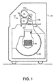
- a supply cassette positioning system shown in Fig. 1 is generally indicated by reference numeral 10.
- the system 10 is mounted within an imagesetter 12 and is shown supporting two media supply cassettes 14a, 14b which contain rolls of photographic media 16 or other image recording material such as paper, lithographic plate, etc. in web form.
- the media supply cassettes 14a, 14b are supported by an upper support tray 18 and a lower support tray 20, respectively.
- the imagesetter 12 has two media supply docking locations to allow the imagesetter operator to select from either supply cassette 14a, 14b which can contain the same types of media, different types of media, or different widths or thicknesses of media.
- a scanning support surface 22 is provided, in this embodiment as an internal drum, for supporting the media 16 drawn out from one of the supply cassettes supported in the docking locations.
- An image scanning apparatus 24 is located above the drum 22 for scanning an image with a modulated energy source (not shown) onto the media 16 supported by the drum 22.
- the supply cassette positioning system is shown having the upper support tray 18 and cassette 14a in the docked, operational position and the lower support tray 20 and supply cassette 14b in a non-operational, access position.
- the upper support tray 18 in the operational position has the supply cassette positioned at the feed rollers 26a, 26b.
- the feed rollers 26a, 26c are driven by conventional means to advance and lead the media 16 from the supply cassette to the scanning support surface 22.
- the middle feed roller 26b is movable between the driven rollers 26a, 26c to cooperate with the driven roller 26a adjacent to the media supply cassette in use 14a.
- Support plates 30 are perpendicular to the longitudinal axes of the supply cassettes 14a, 14b and of the feed rollers 26a,b,c and are located at the ends thereof to support the feed rollers 26a,b,c for rotation.
- Positioning guides 32a, 32b are provided in the support plates 30 to mount the supply cassettes 14a, 14b into their respective docked locations at the feed rollers 26a,b,c.
- Each supply roll 34a, 34b contained in the supply cassettes 14a, 14b is supported by a spindle 36a, 36b which is inserted through the core of the supply roll.
- the ends of the spindles 36a, 36b extend through the ends of the supply cassette 14a, 14b and are received by the guides 32a, 32b, respectively, of the support plates 30 to guide the cassettes 14a, 14b into position at the feed rollers 26a,b,c.
- the lower support tray 20 is fixed to two laterally spaced rods 40 (one shown) which slide linearly with respect to the positioning guides 32b.
- Each rod 40 is slideably supported by at least one linear bearing 42, allowing the lower support tray 20 to be pulled out manually by the operator from the operational position at the feed rollers 26a,b,c, to the access position shown in Fig. 2 in which the cassette 14b can be opened and reloaded with another supply roll of media or the cassette 14b can be removed from the support tray 20 and the imagesetter.
- the imagesetter has covers 44 which open allowing the operator to access the media supply area of the imagesetter.
- the supply cassette has a lid 46 which can be opened about hinge 47 to access the media supply.
- the lid and lower portion of the supply cassette have a bore formed therein to accommodate the spindle such that the lid can open and closed around the spindle ends.
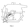
- a locking mechanism is located at each end of the support tray 20 to secure the cassette 14b in several different orientations with respect to the support tray 20.
- the locking mechanism 50 is mounted to the end bracket 52 secured to the end of the support tray 20.
- a sliding member 54 is supported by the bracket 52 between the end of the supply cassette and the bracket 52.
- the sliding member 54 has two pins 56, 58 cooperating with a slot 60 provided in the bracket 52 to guide the movement of the sliding member 54.
- the pins 56, 58 pass through the bracket slot 60 to the opposite side of the bracket 52 where a spring 62 is attached to the pin 58 on the sliding member 54 and to another pin 64 on the bracket 52.
- the spring 62 urges the sliding member 54 into engagement with a locking pin 66 to lock the supply cassette 14b into the support tray 20.
- a rotatable shaft 68 mounted through a bore 70 in the front of the support tray 20 extends past the end bracket 52.
- a lever 72 is attached on each end of the shaft 68 to enable the operator to actuate the locking mechanism 50 from either end of the support tray 20.
- the lever 72 has a slot 74 which the pin 56 on the sliding member 54 also passes through.
- the sliding member 54 Upon pivoting the lever 72 and the rotatable shaft 68, the sliding member 54 is pulled downward and forward by engagement of the pin 56 in the lever slot 74 and the bracket slot 60.
- the locking pin 66 becomes disengaged from the sliding member 54 and the supply cassette 14b is free to be lifted or rotated out of the support tray 20.
- the bottom of the supply cassette 14b is fully supported within the support tray 20 and the locking pin 66 is engaged with the locking mechanism 50.
- a handle 76 is provided on the top of the supply cassette 14b to facilitate removal of the cassette 14b from the support tray 20. With the support tray 20 in the access position, the cassette 14b can be removed from the support tray by lifting the cassette 14b vertically.
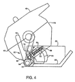
- the locking mechanism 50 on the lower support tray 20 is provided with an intermediate position which supports the supply cassette 14b in a rotated position relative to the support tray 20, to facilitate supply roll replacement.
- the sliding member 54 has a recess 80 for receiving the locking pin 66 when the cassette 14b is rotated approximately forty degrees from the horizontal position to the intermediate position.
- the cassette bottom has a semicylindrical, longitudinal recess 82 which receives the front lip 84 of the lower support tray 20.
- the front lip 84 has a rounded shape which cooperates with the recess 82 of the cassette bottom, acting as a detachable hinge and allowing for supported rotation of the cassette with respect to the support tray. A substantial amount of the weight of the supply cassette bears against the front lip 84 of the support tray during rotation, enabling easily manipulation by an operator.
- the rounded front lip 84 further prevents the cassette 14b from sliding horizontally off the support tray 20.
- the lever 72 is rotated downward about the axis of the bore 70 (counterclockwise in Fig. 4), the sliding member 54 is retracted against the force of the spring 62 by engagement of the pin 56 in the lever slot 74.
- the cassette 14b is manually rotated about the front lip 84 of the support tray 20 causing the locking pin 66 to pass around the edge of the retracted sliding member 54.
- the lever 72 is released and the sliding member 54 is pulled back by the spring 62, securing the locking pin 66 in the recess 80 and locking the cassette 14b into the intermediate position.
- an operator can open the lid 46 of the supply cassette 14b for easy supply roll replacement while the supply cassette 14b remains secured to the lower support tray 20.
- the lever 72 can be pivoted downward to retract the sliding member 54 and release the locking pin 66 from the sliding member 54.
- the cassette is then manually rotated with the weight of the cassette 14b bearing on the front lip 84 of the lower support tray 20 approximately ninety degrees from the horizontal docking position, or approximately fifty degrees from the intermediate position described above, at which point the locking pin 66 clears the sliding member 54 and the cassette is disengaged from the locking mechanism 50 completely.
- the lever 72 is then released, and the cassette 14b is rolled onto its backside onto a roll-up table or other suitable support means (not shown).
- the grooved portion 82 on the bottom of the cassette 14b is positioned against the front lip 84 of the lower support tray 20 by manual maneuvering of the roll-up table.
- the lever 72 is pulled downward to retract the sliding member 54 while the cassette 14b is rotated approximately ninety degrees into the lower support tray 20 from the table.
- the lever 72 is then released by the operator, actuating the locking mechanism 50 by engaging the locking pin 66 with the sliding member 54, thereby securing the cassette 14b within the support tray 20.
- the tray 20 can then be returned to the operational position as shown in Fig. 1, by sliding the lower support tray into the docking location. Engagement of the spindle ends 36b (Fig. 2) in the positioning guides 32b aligns the supply cassette 14b with respect to the feed rollers 26b, 26c.
- the upper support tray 18 and cassette 14a are shown in the docked position.
- the docked position has the supply cassette 14a positioned at the feed rollers 26a, 26b for extracting the media from the supply cassette and advancing it onto the scanning support surface.
- the ends of the spindle 36a protrude from the supply cassette 14a and cooperate with and are received in the positioning guides 32a to position the cassette 14a with respect to the feed rollers 26a, 26b.
- the upper support tray 18 and cassette 14a are angled downward when in the docked position relative to the horizontal docking position of the lower support tray 20 and cassette 14b.
- the upper support tray 18 is fixed to a support arm 90 which is pivotable about a pivot pin 92.
- the pivotable support arm 90 When the upper support tray 18 is in the docked position, the pivotable support arm 90 is generally vertical and the upper support tray 18 is angled downward toward the feed rollers 26a, 26b.
- the supply cassette 14a is secured to the upper tray by a locking mechanism as described with reference to the lower support tray and cassette.
- the support arm 90 When the support arm 90 is pivoted approximately ninety degrees about pivot pin 92, as in Fig. 6, the upper tray 18 and supply cassette 14a are in the access position.
- the upper tray 18 is lowered considerably to about the same position as the lower support tray 20 when pulled out to the access position.
- the upper support tray 18 and cassette 14a are already positioned for reloading without the need for rotation of the cassette 14a relative to the support tray 18.
- the cassette 14a is angled upward about forty degrees from the horizontal position, which is generally the same orientation as the supply cassette 14b located in the lower support tray 20 when rotated to the intermediate position of the locking mechanism 50.
- the support arm 90 facilitates reloading of the supply roll of media while the cassette 14a remains secured to the support tray 18 via the locking mechanism, shown in Figs.
- the pivotable support arm 90 for the upper support tray 18 has a counterbalancing mechanism 100 to assist the operator with positioning the supply cassette 14a between the upper docking location and the access position.
- a pivotable rod 102 mounted inside of the support arm 90 pivots about pivot pin 104 as the support arm 90 pivots about pivot pin 92.
- the pivot pins 92, 104 are fixed to the imagesetter frame 106 and the rod 102 is allowed to pivot inside the arm 90 to effect a change in the relative distance between the pivot point 104 and a flange 108 fixed to the inside of the arm 90.
- the distance between the pivot pin 104 and the flange 108 is largest when the support arm 90 is horizontal.
- a compression spring 110 is coiled around the rod 102 and is compressed between the flange 108 and a stop 112 on the end of the rod 102.
- the supply cassette can have a weight ranging from approximately 7 kg (15 pounds) when empty and constructed of structural foam plus the spindle, to about 27 kg (60 pounds) when full of large format media 91 cm (36") wide and constructed of cast aluminum plus the spindle, for example.
- the compression spring 110 has a relatively large spring constant, k, to create a force, F, large enough to counterbalance the heaviest supply cassette supported by the pivoting support arm 90.
- the force F created by the spring 110 during pivoting of the arm 90 from the vertical position to the horizontal position is directly proportional to the amount the spring is compressed along the rod 102. Therefore, regardless of the weight supported by the support arm 90, the counterbalance force is determined by the position of the support arm. As a result, for lighter loads the counterbalancing mechanism force can pull the support arm back to the upright position undesirably.
- the preferred embodiment of the invention includes a damping mechanism such as a hydraulic damper 120 mounted on each end of the support arm 90.
- the damper viewed in Figs. 5 and 6 is attached to the support plate 30 at pivot pin 122 and to the support arm at pivot pin 124.
- the damper 120 has a plunger rod 126 mounted telescopically relative to a cylinder 128 which is filled with a damping fluid.
- the plunger rod 126 moves telescopically within the cylinder 128 during pivotal movement of the support arm 90.
- the damper 120 resists the counterbalance force when light loads are being supported on the upper support tray 18 and prevents the support arm 90 from swinging back up to the vertical position. For heavy loads, the damper 120 prevents the support arm 90 from pivoting too quickly from the vertical position to the horizontal position under the weight of the supply cassette 14a. It will be appreciated that other suitable damping mechanisms may be substituted for the hydraulic damper.
- the locking mechanism is released and the cassette is rotated by the imagesetter operator with the weight of the supply cassette bearing on the front lip of the supply tray.
- the rotation of the cassette with respect to the support tray is supported by the front lip and is manipulated with little effort by the operator.
- the cassette is rotated approximately fifty degrees until the cassette separates from the supply tray at the detachable hinge, as described previously for the lower support tray and supply cassette.
- the cassette can be released onto a roll-up table or another suitable support means.
Landscapes
- Physics & Mathematics (AREA)
- General Physics & Mathematics (AREA)
- Replacement Of Web Rolls (AREA)
- Paper Feeding For Electrophotography (AREA)
- Sheets, Magazines, And Separation Thereof (AREA)
Description
- The invention is related to media supply cassette handling, and more specifically to installation and removal of large format media supply cassettes used in imagesetters.
- Imagesetters typically have a supply roll of photosensitive media in a light-safe supply cassette, a recording support surface, and an image scanning system for scanning an image onto the media. The media passes from the supply roll supported in the supply cassette, to the recording support surface where the photosensitive media is exposed by the image scanning system. The exposed media is transported in web form into a take-up cassette for storage in a light-safe environment. Otherwise, the media is transported by a conveyor directly from the imagesetter to a processor for developing. When the supply roll runs out or when the operator requires a different media type for imaging, the supply cassette is removed by the operator and reloaded with a new supply roll, or replaced by another media supply cassette containing the different media type.
- Large format media supply cassettes are relatively bulky and heavy for manual manipulation, as typically they can accommodate supply rolls 91cm (36 inches) in width, for example. A fully loaded supply cassette can range in weight from approximately 16 to 27 kg (30 to 60 pounds), depending on the width of the media and the construction material of the supply cassette. Manual loading and installation of the large format media into an imagesetter usually requires two operators due to the bulk and weight of the loaded supply cassette. It is desirable to assist a single operator so as to easily manipulate such large format supply cassettes during installation and removal to increase productivity.
- DE 37 13 170 A1 describes a photographic printer with a station for accommodating a mobile, carriage-like cassette in an operative position. The operative station receives a take-off cassette, carrying a reel of photographic material. An additional station holds a replacement cassette in a ready position.
- EP 0 461 467 A2 describes a travel roller moving between an initial and an end point, while supporting photosensitive material. The photosensitive material is exposed by an expose-scanning unit.
- EP 0 561 438 A1 describes a daylight reloadable lighttight cassette for holding a roll of light-sensitive web.
- It is accordingly a general object of the present invention to assist an imagesetter operator with large format media supply cassette reloading, installation and removal.
- It is another object of the invention to allow a single operator to install, remove and reload a media supply cassette without requiring any lifting of the supply cassette by the operator.
- It is yet another object of the invention to facilitate reloading or removal of a supply cassette from an imagesetter while another supply cassette is in use by the imagesetter.
- It is a specific object of the invention to provide an assist mechanism to pivot a large format media supply cassette from an upper docked position to a lower access position and to counterbalance the assist mechanism that performs the pivoting of the supply cassette between the docked position to the access position.
- The above mentioned objects are realised by a positioning apparatus having the specific features set out in claim 1, by an imagesetting device having the specific features set out in claim 5 and by a method having the specific features set out in claim 6. Specific features for preferred embodiments of the invention are set out in the dependent claims.
- The media supply cassette to be used in said positioning apparatus and in said image setting device contains a media supply roll and the media supply cassette is supported by a movable support in the imagesetter. The movable support has two functional positions, an operational position in which the media supply cassette supplies media to the imagesetter, and an access position in which the media supply cassette is easily accessible for reloading the media supply cassette with a media supply roll. The access position is also for installing and removing the media supply cassette to and from the movable support. Loading a media supply cassette into the imagesetter involves first installing a media supply cassette onto the movable support in the imagesetter while the movable support is in the access position; automatically securing the media supply cassette to the movable support with a locking mechanism; positioning the movable support from the access position to the operational position with the media supply cassette secured to the movable support, and supplying media from the media supply roll contained in the media supply cassette to the imagesetter.
- A supply cassette positioning apparatus positions a first supply cassette containing a first roll of web material and a second supply cassette containing a second roll of web material. A first movable support for supporting the first supply cassette is movable between a first position and a second position. The first position supports the first supply cassette in an operational position in which the material is drawn from the first roll of web material, and the second position supports the first supply cassette in an access position in which the first supply cassette can be reloaded with a new roll of web material while the first supply cassette is supported by the first movable support and in which the first supply cassette can be removed from the first movable support. A second movable support for supporting the second supply cassette is movable between a first position and a second position. The first position supports the second supply cassette in an operating position in which the material is drawn from the second roll of web material, and the second position supports the second supply cassette in an access position in which the second supply cassette can be reloaded with a new roll of web material while the second supply cassette is supported by the second movable support and in which the second supply cassette can be removed from the second movable support.
- The features and objects of the invention will become apparent in the following description taken with the accompanying drawings, in which:
- Figure 1 is an illustrative side view of an imagesetter employing a media supply cassette positioning system according to the invention.
- Figure 2 is an illustrative side view of the imagesetter in Fig. 1 showing a lower supply cassette positioned in an access position by means of the media supply cassette positioning system according to the invention.
- Figure 3 is an illustrative side view of a media supply cassette secured to a support tray of the media supply cassette positioning system by a locking mechanism.
- Figure 4 is an illustrative side view of the media supply in Fig. 3 rotated to an intermediate position with respect to the support tray and secured by the locking mechanism.
- Figure 5 is an illustrative side view of a pivotable support arm of the media supply cassette positioning system positioning an upper supply cassette according to the invention.
- Figure 6 is an illustrative side view of the support arm in Fig. 5 positioning the upper supply cassette into an access position and a counterbalancing mechanism according to the invention.
-
- A supply cassette positioning system shown in Fig. 1 is generally indicated by
reference numeral 10. Thesystem 10 is mounted within animagesetter 12 and is shown supporting twomedia supply cassettes photographic media 16 or other image recording material such as paper, lithographic plate, etc. in web form. Themedia supply cassettes upper support tray 18 and alower support tray 20, respectively. Theimagesetter 12 has two media supply docking locations to allow the imagesetter operator to select from eithersupply cassette scanning support surface 22 is provided, in this embodiment as an internal drum, for supporting themedia 16 drawn out from one of the supply cassettes supported in the docking locations. Animage scanning apparatus 24 is located above thedrum 22 for scanning an image with a modulated energy source (not shown) onto themedia 16 supported by thedrum 22. - Referring to Figure 2, the supply cassette positioning system is shown having the upper support tray 18 and
cassette 14a in the docked, operational position and thelower support tray 20 andsupply cassette 14b in a non-operational, access position. The upper support tray 18 in the operational position has the supply cassette positioned at thefeed rollers feed rollers media 16 from the supply cassette to thescanning support surface 22. Themiddle feed roller 26b is movable between the drivenrollers roller 26a adjacent to the media supply cassette inuse 14a. -
Support plates 30 are perpendicular to the longitudinal axes of thesupply cassettes feed rollers 26a,b,c and are located at the ends thereof to support thefeed rollers 26a,b,c for rotation.Positioning guides support plates 30 to mount thesupply cassettes feed rollers 26a,b,c. Eachsupply roll supply cassettes spindle spindles supply cassette guides support plates 30 to guide thecassettes feed rollers 26a,b,c. - The
lower support tray 20 is fixed to two laterally spaced rods 40 (one shown) which slide linearly with respect to thepositioning guides 32b. Eachrod 40 is slideably supported by at least one linear bearing 42, allowing the lower support tray 20 to be pulled out manually by the operator from the operational position at thefeed rollers 26a,b,c, to the access position shown in Fig. 2 in which thecassette 14b can be opened and reloaded with another supply roll of media or thecassette 14b can be removed from thesupport tray 20 and the imagesetter. The imagesetter has covers 44 which open allowing the operator to access the media supply area of the imagesetter. - Referring to Fig. 3, it can be seen the supply cassette has a
lid 46 which can be opened abouthinge 47 to access the media supply. The lid and lower portion of the supply cassette have a bore formed therein to accommodate the spindle such that the lid can open and closed around the spindle ends. A locking mechanism, generally indicated byreference numeral 50, is located at each end of the support tray 20 to secure thecassette 14b in several different orientations with respect to thesupport tray 20. Thelocking mechanism 50 is mounted to theend bracket 52 secured to the end of thesupport tray 20. A slidingmember 54 is supported by thebracket 52 between the end of the supply cassette and thebracket 52. The slidingmember 54 has twopins slot 60 provided in thebracket 52 to guide the movement of the slidingmember 54. Thepins bracket slot 60 to the opposite side of thebracket 52 where aspring 62 is attached to thepin 58 on the slidingmember 54 and to anotherpin 64 on thebracket 52. Thespring 62 urges the slidingmember 54 into engagement with alocking pin 66 to lock thesupply cassette 14b into thesupport tray 20. Arotatable shaft 68 mounted through abore 70 in the front of thesupport tray 20 extends past theend bracket 52. Alever 72 is attached on each end of theshaft 68 to enable the operator to actuate thelocking mechanism 50 from either end of thesupport tray 20. Thelever 72 has aslot 74 which thepin 56 on the slidingmember 54 also passes through. Upon pivoting thelever 72 and therotatable shaft 68, the slidingmember 54 is pulled downward and forward by engagement of thepin 56 in thelever slot 74 and thebracket slot 60. When the slidingmember 54 is retracted by thelever 72, the lockingpin 66 becomes disengaged from the slidingmember 54 and thesupply cassette 14b is free to be lifted or rotated out of thesupport tray 20. The bottom of thesupply cassette 14b is fully supported within thesupport tray 20 and the lockingpin 66 is engaged with thelocking mechanism 50. Ahandle 76 is provided on the top of thesupply cassette 14b to facilitate removal of thecassette 14b from thesupport tray 20. With thesupport tray 20 in the access position, thecassette 14b can be removed from the support tray by lifting thecassette 14b vertically. It is not necessary to actuate thelever 72 to retract the slidingmember 54 because the lockingpin 66 overcomes the slidingmember 54 by a slight forward movement of the cassette (to the right in Fig. 3) while lifting in a generally vertical direction. Replacement of thecassette 14b into thesupport tray 20 in a downward vertical direction also does not require thelever 72 to be actuated for the lockingpin 66 to engage thelocking mechanism 50 and secure the cassette for docking. - Referring to Fig. 3 and 4, the
locking mechanism 50 on thelower support tray 20 is provided with an intermediate position which supports thesupply cassette 14b in a rotated position relative to thesupport tray 20, to facilitate supply roll replacement. The slidingmember 54 has arecess 80 for receiving the lockingpin 66 when thecassette 14b is rotated approximately forty degrees from the horizontal position to the intermediate position. The cassette bottom has a semicylindrical,longitudinal recess 82 which receives thefront lip 84 of thelower support tray 20. Thefront lip 84 has a rounded shape which cooperates with therecess 82 of the cassette bottom, acting as a detachable hinge and allowing for supported rotation of the cassette with respect to the support tray. A substantial amount of the weight of the supply cassette bears against thefront lip 84 of the support tray during rotation, enabling easily manipulation by an operator. The roundedfront lip 84 further prevents thecassette 14b from sliding horizontally off thesupport tray 20. - To support the supply cassette for roll replacement, the
lever 72 is rotated downward about the axis of the bore 70 (counterclockwise in Fig. 4), the slidingmember 54 is retracted against the force of thespring 62 by engagement of thepin 56 in thelever slot 74. Thecassette 14b is manually rotated about thefront lip 84 of thesupport tray 20 causing the lockingpin 66 to pass around the edge of the retracted slidingmember 54. When the lockingpin 66 is aligned with therecess 80, thelever 72 is released and the slidingmember 54 is pulled back by thespring 62, securing the lockingpin 66 in therecess 80 and locking thecassette 14b into the intermediate position. With the angled intermediate position, an operator can open thelid 46 of thesupply cassette 14b for easy supply roll replacement while thesupply cassette 14b remains secured to thelower support tray 20. - To remove the
supply cassette 14b from thelower support tray 20 without requiring an operator to manually lift the supply cassette, thelever 72 can be pivoted downward to retract the slidingmember 54 and release the lockingpin 66 from the slidingmember 54. The cassette is then manually rotated with the weight of thecassette 14b bearing on thefront lip 84 of thelower support tray 20 approximately ninety degrees from the horizontal docking position, or approximately fifty degrees from the intermediate position described above, at which point the lockingpin 66 clears the slidingmember 54 and the cassette is disengaged from thelocking mechanism 50 completely. Thelever 72 is then released, and thecassette 14b is rolled onto its backside onto a roll-up table or other suitable support means (not shown). - To return the cassette from the table to the
lower support tray 20, the groovedportion 82 on the bottom of thecassette 14b is positioned against thefront lip 84 of thelower support tray 20 by manual maneuvering of the roll-up table. Thelever 72 is pulled downward to retract the slidingmember 54 while thecassette 14b is rotated approximately ninety degrees into thelower support tray 20 from the table. Thelever 72 is then released by the operator, actuating thelocking mechanism 50 by engaging the lockingpin 66 with the slidingmember 54, thereby securing thecassette 14b within thesupport tray 20. Thetray 20 can then be returned to the operational position as shown in Fig. 1, by sliding the lower support tray into the docking location. Engagement of the spindle ends 36b (Fig. 2) in the positioning guides 32b aligns thesupply cassette 14b with respect to thefeed rollers - Referring to Figs. 5 and 6, the
upper support tray 18 andcassette 14a are shown in the docked position. The docked position has thesupply cassette 14a positioned at thefeed rollers spindle 36a protrude from thesupply cassette 14a and cooperate with and are received in the positioning guides 32a to position thecassette 14a with respect to thefeed rollers upper support tray 18 andcassette 14a are angled downward when in the docked position relative to the horizontal docking position of thelower support tray 20 andcassette 14b. Theupper support tray 18 is fixed to asupport arm 90 which is pivotable about apivot pin 92. When theupper support tray 18 is in the docked position, thepivotable support arm 90 is generally vertical and theupper support tray 18 is angled downward toward thefeed rollers supply cassette 14a is secured to the upper tray by a locking mechanism as described with reference to the lower support tray and cassette. - When the
support arm 90 is pivoted approximately ninety degrees aboutpivot pin 92, as in Fig. 6, theupper tray 18 andsupply cassette 14a are in the access position. Theupper tray 18 is lowered considerably to about the same position as thelower support tray 20 when pulled out to the access position. Theupper support tray 18 andcassette 14a are already positioned for reloading without the need for rotation of thecassette 14a relative to thesupport tray 18. Thecassette 14a is angled upward about forty degrees from the horizontal position, which is generally the same orientation as thesupply cassette 14b located in thelower support tray 20 when rotated to the intermediate position of thelocking mechanism 50. Thesupport arm 90 facilitates reloading of the supply roll of media while thecassette 14a remains secured to thesupport tray 18 via the locking mechanism, shown in Figs. 3 and 4, as previously described with regard to the lower supply cassette. It should be noted that since thesupply cassette 14a is already positioned for reloading when thesupport arm 90 is horizontal, the locking mechanism on the upper support tray does not require the intermediate position as described with respect to the lower support tray. - The
pivotable support arm 90 for theupper support tray 18 has acounterbalancing mechanism 100 to assist the operator with positioning thesupply cassette 14a between the upper docking location and the access position. Apivotable rod 102 mounted inside of thesupport arm 90 pivots aboutpivot pin 104 as thesupport arm 90 pivots aboutpivot pin 92. The pivot pins 92, 104 are fixed to theimagesetter frame 106 and therod 102 is allowed to pivot inside thearm 90 to effect a change in the relative distance between thepivot point 104 and aflange 108 fixed to the inside of thearm 90. The distance between thepivot pin 104 and theflange 108 is largest when thesupport arm 90 is horizontal. Acompression spring 110 is coiled around therod 102 and is compressed between theflange 108 and astop 112 on the end of therod 102. Upon pivotal movement of thesupport arm 90 aboutpivot pin 92 from the vertical position toward the horizontal position, the distance between thepivot pin 104 and theflange 108 increases, thereby increasing the compression of thespring 110 and creating a force F in the direction of thepivot pin 104 that counterbalances the moment M aroundpivot pin 92 caused by the weight of thesupply cassette 14a. The supply cassette can have a weight ranging from approximately 7 kg (15 pounds) when empty and constructed of structural foam plus the spindle, to about 27 kg (60 pounds) when full of large format media 91 cm (36") wide and constructed of cast aluminum plus the spindle, for example. Consequently, thecompression spring 110 has a relatively large spring constant, k, to create a force, F, large enough to counterbalance the heaviest supply cassette supported by the pivotingsupport arm 90. The force F created by thespring 110 during pivoting of thearm 90 from the vertical position to the horizontal position is directly proportional to the amount the spring is compressed along therod 102. Therefore, regardless of the weight supported by thesupport arm 90, the counterbalance force is determined by the position of the support arm. As a result, for lighter loads the counterbalancing mechanism force can pull the support arm back to the upright position undesirably. - The preferred embodiment of the invention includes a damping mechanism such as a
hydraulic damper 120 mounted on each end of thesupport arm 90. The damper viewed in Figs. 5 and 6 is attached to thesupport plate 30 atpivot pin 122 and to the support arm atpivot pin 124. Thedamper 120 has aplunger rod 126 mounted telescopically relative to acylinder 128 which is filled with a damping fluid. Theplunger rod 126 moves telescopically within thecylinder 128 during pivotal movement of thesupport arm 90. Thedamper 120 resists the counterbalance force when light loads are being supported on theupper support tray 18 and prevents thesupport arm 90 from swinging back up to the vertical position. For heavy loads, thedamper 120 prevents thesupport arm 90 from pivoting too quickly from the vertical position to the horizontal position under the weight of thesupply cassette 14a. It will be appreciated that other suitable damping mechanisms may be substituted for the hydraulic damper. - To remove the supply cassette from the upper support tray without manually lifting the supply cassette, the locking mechanism is released and the cassette is rotated by the imagesetter operator with the weight of the supply cassette bearing on the front lip of the supply tray. The rotation of the cassette with respect to the support tray is supported by the front lip and is manipulated with little effort by the operator. The cassette is rotated approximately fifty degrees until the cassette separates from the supply tray at the detachable hinge, as described previously for the lower support tray and supply cassette. The cassette can be released onto a roll-up table or another suitable support means.
- While this invention has been described in terms of various preferred embodiments, those skilled in the art will appreciate that various modifications, substitutions, omissions and changes may be made. Accordingly, it is intended that the scope of the present invention be limited solely by the scope of the following claims.
Claims (10)
- A positioning apparatus (10) for an imagesetting device (12) comprising:characterised in that said movable support (20) comprises means (40, 42) for sliding linearly from said operational position to said access position and has a locking mechanism (50) for securing the cassette (14b) in several different rotated orientations with respect to said movable support (20).a first supply cassette (14b) containing a roll (34b) of web material;a movable support (20) for supporting and moving said supply cassette (14b), said movable support (20) being movable between a first position and a second position the first position for supporting the supply cassette (14b) in an operational position in which the web material can be with drawn from said roll (34b) of web material, and the second position for supporting the supply cassette (14b) in an access position in which said supply cassette (14b) can be reloaded with a new roll of web material while said supply cassette (14b) is supported by said movable support (20) and in which said supply cassette (14b) can be removed from said movable support (20);
- The positioning apparatus (10) according to claim 1, further comprising:a second supply cassette (14a) containing a second roll (34a) of web material;a second movable support (18) for supporting and pivotally moving said second supply cassette (14a), said second movable support (18) being movable between a first position in which the second supply cassette is superimposed to said first supply cassette and a second position, the first position for supporting the second supply cassette (14a) in an operational position in which the web material can be drawn from said second roll (34a) of web material, and the second position for supporting the second supply cassette (14a) in an access position in which said second supply cassette (14a) can be reloaded with a new roll of web material while said second supply cassette (14a) is supported by said second movable support (18) and in which said second supply cassette (14a) can be removed from said second movable support (18).
- The positioning apparatus (10) according to any one of the preceding claims, wherein at least one movable support (18, 20) includes counterbalancing means (100) for counterbalancing the weight of said first or second supply cassette (14a, 14b) during movement between said first and second position.
- The positioning apparatus (10) according to any one of the preceding claims, wherein at least one movable support (18, 20) includes damping means (120) for damping the movement of the movable support (18, 20) between said first and second position.
- An imagesetting device (12), comprising:the positioning apparatus (10) according to any one of the preceding claims, wherein the web material is image recording media;means (22) for supporting said media from a supply cassette (14a, 14b), when said media is withdrawn from said supply cassette (14a, 14b);an image scanning means (24) for scanning an image onto said media, when supported by said media supporting means (22).
- A method of installation, removal and reloading a supply cassette (14a, 14b) in a positioning apparatus (10) according to any one of the preceding claims 1-4, or an imagesetting device (12) according to claim 5 comprising the steps of:installing a supply cassette (14a, 14b) onto a movable support (18, 20) in said positioning apparatus (10) or imagesetting device (12) while the movable support (18, 20) is in the access position; support (18, 20) is in the access position;automatically securing the supply cassette (14a, 14b) to the movable support (18, 20) by a locking mechanism (50);positioning the movable support (18, 20) from the access position to the operational position, with the supply cassette (14a, 14b) secured to the movable support (18, 20); and,supplying web material from the roll (34a, 34b) in the supply cassette (14a, 14b) to said positioning apparatus (10) or imagesetting device (12).
- The method according to claim 6, further comprising the steps of:positioning the movable support (18, 20) from the operational position to the access position, with the supply cassette (14a, 14b) secured to the movable support; and,reloading the supply cassette (14a, 14b) with a new supply roll (34a, 34b) while the supply cassette (14a, 14b) is secured to the movable support (18, 20) in the access position.
- The method according to claim 6, further comprising the steps of:positioning the movable support (18, 20) from the operational position to the access position with the supply cassette (14a, 14b) secured to the movable support; and,releasing the locking mechanism (50) and removing the supply cassette (14a, 14b) from the movable support (18, 20).
- The method according to any one of claims 6 to 8, wherein the step of positioning the movable support (18, 20) includes moving a movable support (18) between the access position and the operational position in a pivotal motion and counterbalancing the pivotal motion of the movable support (18, 20).
- The method according to claim 9, further including damping the pivotal motion of the movable support to accommodate the varying loads on the movable support.
Applications Claiming Priority (2)
| Application Number | Priority Date | Filing Date | Title |
|---|---|---|---|
| US08/329,030 US5684570A (en) | 1994-10-25 | 1994-10-25 | Method and apparatus for manipulation of large format media supply cassettes |
| US329030 | 1994-10-25 |
Publications (2)
| Publication Number | Publication Date |
|---|---|
| EP0714045A1 EP0714045A1 (en) | 1996-05-29 |
| EP0714045B1 true EP0714045B1 (en) | 2002-01-23 |
Family
ID=23283564
Family Applications (1)
| Application Number | Title | Priority Date | Filing Date |
|---|---|---|---|
| EP95202326A Expired - Lifetime EP0714045B1 (en) | 1994-10-25 | 1995-08-29 | Method and apparatus for manipulation of large format media supply cassettes |
Country Status (4)
| Country | Link |
|---|---|
| US (1) | US5684570A (en) |
| EP (1) | EP0714045B1 (en) |
| JP (1) | JPH08208082A (en) |
| DE (1) | DE69525133T2 (en) |
Families Citing this family (7)
| Publication number | Priority date | Publication date | Assignee | Title |
|---|---|---|---|---|
| US6698959B2 (en) * | 2000-12-13 | 2004-03-02 | Fuji Photo Film Co., Ltd. | Printer for printing paper roll having a position regulating device |
| DE10223412B4 (en) * | 2002-05-25 | 2011-11-10 | Leica Biosystems Nussloch Gmbh | Tableau for holding cassettes and / or slides for histological or cytological preparations |
| US20050210839A1 (en) * | 2004-03-24 | 2005-09-29 | Sealed Air Corporation (Us) | Overhead packaging cushion supply system |
| US9254698B2 (en) * | 2007-01-26 | 2016-02-09 | Hewlett-Packard Development Company, L.P. | Printing apparatus |
| JP2012006728A (en) * | 2010-06-25 | 2012-01-12 | Seiko Epson Corp | Consumable product accommodating device, liquid ejection apparatus and method of controlling consumable product accommodating device |
| JP5663978B2 (en) * | 2010-06-29 | 2015-02-04 | セイコーエプソン株式会社 | Roll medium storage device and liquid ejecting device |
| KR20150085358A (en) * | 2014-01-15 | 2015-07-23 | 삼성전자주식회사 | Image forming apparatus |
Citations (1)
| Publication number | Priority date | Publication date | Assignee | Title |
|---|---|---|---|---|
| EP0561438A1 (en) * | 1992-03-19 | 1993-09-22 | Agfa-Gevaert N.V. | A reloadable lighttight plastic cassette |
Family Cites Families (8)
| Publication number | Priority date | Publication date | Assignee | Title |
|---|---|---|---|---|
| US4218135A (en) * | 1977-06-24 | 1980-08-19 | Olympus Optical Co., Ltd. | Roll sheet cassette loading apparatus |
| US4135805A (en) * | 1977-08-04 | 1979-01-23 | Xerox Corporation | Counterbalancing apparatus |
| DE3713170A1 (en) * | 1987-04-17 | 1988-11-03 | Agfa Gevaert Ag | PHOTOGRAPHIC DEVICE FOR THE PROCESSING OF PHOTOGRAPHIC REEL MATERIAL THAT CAN BE PLACED IN MOBILE CASSETTE |
| JP2519820B2 (en) * | 1990-06-15 | 1996-07-31 | 大日本スクリーン製造株式会社 | Flatbed scanning image recorder |
| DE4031024A1 (en) * | 1990-10-01 | 1992-04-02 | Agfa Gevaert Ag | PHOTOGRAPHIC ROLL COPIER WITH OVERHEAD PAPER RUN |
| JP2915619B2 (en) * | 1991-05-13 | 1999-07-05 | 富士写真フイルム株式会社 | Paper magazine mounting device and method |
| DE59206990D1 (en) * | 1991-08-13 | 1996-10-02 | Agfa Gevaert Ag | Photographic copier with a storage cassette |
| DE59208711D1 (en) * | 1992-05-22 | 1997-08-21 | Gretag Imaging Ag | Copier for copying master copies onto sheet-like copy material |
-
1994
- 1994-10-25 US US08/329,030 patent/US5684570A/en not_active Expired - Fee Related
-
1995
- 1995-08-29 EP EP95202326A patent/EP0714045B1/en not_active Expired - Lifetime
- 1995-08-29 DE DE69525133T patent/DE69525133T2/en not_active Expired - Fee Related
- 1995-10-20 JP JP7295926A patent/JPH08208082A/en active Pending
Patent Citations (1)
| Publication number | Priority date | Publication date | Assignee | Title |
|---|---|---|---|---|
| EP0561438A1 (en) * | 1992-03-19 | 1993-09-22 | Agfa-Gevaert N.V. | A reloadable lighttight plastic cassette |
Also Published As
| Publication number | Publication date |
|---|---|
| EP0714045A1 (en) | 1996-05-29 |
| US5684570A (en) | 1997-11-04 |
| JPH08208082A (en) | 1996-08-13 |
| DE69525133T2 (en) | 2002-08-22 |
| DE69525133D1 (en) | 2002-03-14 |
Similar Documents
| Publication | Publication Date | Title |
|---|---|---|
| US6904844B2 (en) | Printing plate removing/supplying device | |
| GB2139984A (en) | Magazine | |
| JP2915619B2 (en) | Paper magazine mounting device and method | |
| US5684570A (en) | Method and apparatus for manipulation of large format media supply cassettes | |
| EP0692739B1 (en) | Method and apparatus for pivotally mounted media transport bridge with improved counterbalance system | |
| US5737988A (en) | System for buffering moving material between two modular machines | |
| US5107296A (en) | Photographic paper transporting apparatus and method for photographic printer | |
| EP0708048B1 (en) | Method and apparatus for installing a media supply cassette in an imagesetter | |
| EP0653667B1 (en) | Support system for paper magazine | |
| US5187520A (en) | Photographic copying apparatus | |
| JPH05265100A (en) | Photocopying apparatus and operating method thereof | |
| US6115106A (en) | Image recording apparatus | |
| JPH082697A (en) | Longitudinal type paper feeding tray for image forming device | |
| KR100449731B1 (en) | Paper supplying cassette of printing apparatus | |
| EP0892304B1 (en) | Installation guide mechanism for paper roll and guide apparatus for paper magazine | |
| US6177981B1 (en) | Loading arrangement and film platform for APS film | |
| US5006874A (en) | Apparatus for recording images on a roll of film and a film winding cartridge | |
| JP2584852B2 (en) | Sheet feeding device | |
| JPH0736756Y2 (en) | Printer | |
| JPH02163228A (en) | Manual paper feeder | |
| JPH04257840A (en) | Printing apparatus for photography | |
| JPH01294146A (en) | Magazine storage device | |
| JPS62173444A (en) | Image recording device | |
| JPH03256951A (en) | Electrostatic recording vertical printer | |
| JPH10236664A (en) | Sheet material storage device and image forming device |
Legal Events
| Date | Code | Title | Description |
|---|---|---|---|
| PUAI | Public reference made under article 153(3) epc to a published international application that has entered the european phase |
Free format text: ORIGINAL CODE: 0009012 |
|
| AK | Designated contracting states |
Kind code of ref document: A1 Designated state(s): BE DE FR GB NL |
|
| 17P | Request for examination filed |
Effective date: 19961129 |
|
| RAP1 | Party data changed (applicant data changed or rights of an application transferred) |
Owner name: AGFA CORPORATION |
|
| RAP1 | Party data changed (applicant data changed or rights of an application transferred) |
Owner name: AGFA CORPORATION |
|
| 17Q | First examination report despatched |
Effective date: 20000904 |
|
| GRAG | Despatch of communication of intention to grant |
Free format text: ORIGINAL CODE: EPIDOS AGRA |
|
| GRAG | Despatch of communication of intention to grant |
Free format text: ORIGINAL CODE: EPIDOS AGRA |
|
| GRAH | Despatch of communication of intention to grant a patent |
Free format text: ORIGINAL CODE: EPIDOS IGRA |
|
| GRAH | Despatch of communication of intention to grant a patent |
Free format text: ORIGINAL CODE: EPIDOS IGRA |
|
| GRAA | (expected) grant |
Free format text: ORIGINAL CODE: 0009210 |
|
| REG | Reference to a national code |
Ref country code: GB Ref legal event code: IF02 |
|
| AK | Designated contracting states |
Kind code of ref document: B1 Designated state(s): BE DE FR GB NL |
|
| PG25 | Lapsed in a contracting state [announced via postgrant information from national office to epo] |
Ref country code: NL Free format text: LAPSE BECAUSE OF FAILURE TO SUBMIT A TRANSLATION OF THE DESCRIPTION OR TO PAY THE FEE WITHIN THE PRESCRIBED TIME-LIMIT Effective date: 20020123 Ref country code: BE Free format text: LAPSE BECAUSE OF FAILURE TO SUBMIT A TRANSLATION OF THE DESCRIPTION OR TO PAY THE FEE WITHIN THE PRESCRIBED TIME-LIMIT Effective date: 20020123 |
|
| REF | Corresponds to: |
Ref document number: 69525133 Country of ref document: DE Date of ref document: 20020314 |
|
| ET | Fr: translation filed | ||
| NLV1 | Nl: lapsed or annulled due to failure to fulfill the requirements of art. 29p and 29m of the patents act | ||
| PLBE | No opposition filed within time limit |
Free format text: ORIGINAL CODE: 0009261 |
|
| STAA | Information on the status of an ep patent application or granted ep patent |
Free format text: STATUS: NO OPPOSITION FILED WITHIN TIME LIMIT |
|
| 26N | No opposition filed | ||
| PGFP | Annual fee paid to national office [announced via postgrant information from national office to epo] |
Ref country code: FR Payment date: 20030619 Year of fee payment: 9 |
|
| PGFP | Annual fee paid to national office [announced via postgrant information from national office to epo] |
Ref country code: GB Payment date: 20030620 Year of fee payment: 9 Ref country code: DE Payment date: 20030620 Year of fee payment: 9 |
|
| PG25 | Lapsed in a contracting state [announced via postgrant information from national office to epo] |
Ref country code: GB Free format text: LAPSE BECAUSE OF NON-PAYMENT OF DUE FEES Effective date: 20040829 |
|
| PG25 | Lapsed in a contracting state [announced via postgrant information from national office to epo] |
Ref country code: DE Free format text: LAPSE BECAUSE OF NON-PAYMENT OF DUE FEES Effective date: 20050301 |
|
| GBPC | Gb: european patent ceased through non-payment of renewal fee |
Effective date: 20040829 |
|
| PG25 | Lapsed in a contracting state [announced via postgrant information from national office to epo] |
Ref country code: FR Free format text: LAPSE BECAUSE OF NON-PAYMENT OF DUE FEES Effective date: 20050429 |
|
| REG | Reference to a national code |
Ref country code: FR Ref legal event code: ST |