EP0713969A2 - Structure for connecting spark plug and ignition coil for internal combustion engine - Google Patents
Structure for connecting spark plug and ignition coil for internal combustion engine Download PDFInfo
- Publication number
- EP0713969A2 EP0713969A2 EP95117454A EP95117454A EP0713969A2 EP 0713969 A2 EP0713969 A2 EP 0713969A2 EP 95117454 A EP95117454 A EP 95117454A EP 95117454 A EP95117454 A EP 95117454A EP 0713969 A2 EP0713969 A2 EP 0713969A2
- Authority
- EP
- European Patent Office
- Prior art keywords
- air vent
- lid portion
- ignition coil
- vent passage
- plug hole
- Prior art date
- Legal status (The legal status is an assumption and is not a legal conclusion. Google has not performed a legal analysis and makes no representation as to the accuracy of the status listed.)
- Granted
Links
Images


Classifications
-
- F—MECHANICAL ENGINEERING; LIGHTING; HEATING; WEAPONS; BLASTING
- F02—COMBUSTION ENGINES; HOT-GAS OR COMBUSTION-PRODUCT ENGINE PLANTS
- F02P—IGNITION, OTHER THAN COMPRESSION IGNITION, FOR INTERNAL-COMBUSTION ENGINES; TESTING OF IGNITION TIMING IN COMPRESSION-IGNITION ENGINES
- F02P13/00—Sparking plugs structurally combined with other parts of internal-combustion engines
-
- H—ELECTRICITY
- H01—ELECTRIC ELEMENTS
- H01T—SPARK GAPS; OVERVOLTAGE ARRESTERS USING SPARK GAPS; SPARKING PLUGS; CORONA DEVICES; GENERATING IONS TO BE INTRODUCED INTO NON-ENCLOSED GASES
- H01T13/00—Sparking plugs
- H01T13/02—Details
- H01T13/06—Covers forming a part of the plug and protecting it against adverse environment
-
- F—MECHANICAL ENGINEERING; LIGHTING; HEATING; WEAPONS; BLASTING
- F02—COMBUSTION ENGINES; HOT-GAS OR COMBUSTION-PRODUCT ENGINE PLANTS
- F02P—IGNITION, OTHER THAN COMPRESSION IGNITION, FOR INTERNAL-COMBUSTION ENGINES; TESTING OF IGNITION TIMING IN COMPRESSION-IGNITION ENGINES
- F02P3/00—Other installations
- F02P3/02—Other installations having inductive energy storage, e.g. arrangements of induction coils
Definitions
- the present invention relates to a structure for connecting an ignition coil and a spark plug for use in an internal combustion engine.
- a spark plug 51 mounted in the bottom of a plug hole H formed in a cylinder head C and an ignition coil 52 fixed on the cylinder head C are electrically connected in a manner to be described below.
- a connecting terminal 53 projecting downwardly from the underside of the ignition coil 52 is electrically connected to a terminal 54 of the spark plug 51 which projects upwardly in the cylinder head C through a conductive member 55 such as a single spring, a metal round bar, and a metal cylinder.
- An insulating member 56 covers an outer periphery of the conductive member 55 to extend from the connecting terminal 53 to the terminal 54.
- insulating members 56 There are two types of insulating members 56.
- One type is an insulating member comprised of three members: a cap for covering the range from the connecting terminal 53 to the conductive member 55, a bushing for covering the range from the terminal 54 to the conductive member 55, and a sleeve for covering the conductive member 55 to extend from the cap to the bushing.
- the other type is an insulating member comprised of the cap, bushing and sleeve which are formed integrally. In either case, the cap or a portion corresponding to the cap is fitted in an upper portion of the plug hole C in such a manner that an upper surface thereof is in intimate contact with the underside of the ignition coil 52 and an outer periphery thereof is in intimate contact with an inner peripheral surface of the plug hole H.
- a first air vent hole 57 is formed in the contact portion between the upper surface of the cap or the portion corresponding to the cap and the bottom surface of the ignition coil 52 and extends from the outer edge of the contact portion.
- a second air vent hole 58 for communication between the first air vent hole 57 and the interior of the plug hole H is formed in the cap or the portion corresponding to the cap.
- the expanded amount of air may be escaped through the first and second air vent holes 57 and 58, preventing changes in pressure in the plug hole H.
- a first aspect of the present invention is directed to a structure for connecting a spark plug and an ignition coil for an internal combustion engine.
- the structure comprises: a spark plug mounted in the bottom of a plug hole formed in a cylinder head; an ignition coil mounted on the cylinder head and having a lid portion for closing an upper opening of the plug hole; and a connecting member for electrically and mechanically connecting the ignition coil and the spark plug in the plug hole, the connecting member including an insulating cap between the lid portion of the ignition coil and the cylinder head and in intimate contact with a bottom surface of the lid portion and a periphery of the upper opening of the plug hole, there being a first air vent passage between the insulating cap and the lid portion and in communication with the exterior, the insulating cap having a second air vent passage for communication between the first air vent passage and the interior of the plug hole, there being a large-volume reservoir space between the insulating cap and the lid portion at a position along the first air vent passage and having a cross-sectional area enlarged from the
- the first air vent passage is defined by a space surrounded by a groove formed in an upper surface of the insulating cap and the bottom surface of the lid portion.
- the first air vent passage is defined by a space surrounded by an upper surface of the insulating cap and a groove formed in the bottom surface of the lid portion.
- the first air vent passage is defined by a space surrounded by a groove formed in an upper surface of the insulating cap and a groove formed in the bottom surface of the lid portion.
- the reservoir space is defined by a space surrounded by a recess formed in the upper surface of the insulating cap and the bottom surface of the lid portion.
- the reservoir space is defined by a space surrounded by the upper surface of the insulating cap and a recess formed in the bottom surface of the lid portion.
- the reservoir space is defined by a space surrounded by a recess formed in the upper surface of the insulating cap and a recess formed in the bottom surface of the lid portion.
- the structure comprises: a spark plug mounted in the bottom of a plug hole formed in a cylinder head; an ignition coil including a bar-shaped coil body portion received in the plug hole, a plug connecting portion at the lower end of the coil body portion and connected to the spark plug, and a lid portion at the upper end of the coil body portion and located exteriorly of the plug hole; and an annular rubber member provided between the lid portion of the ignition coil and the cylinder head and in intimate contact with a bottom surface of the lid portion and a periphery of an upper opening of the plug hole, there being a first air vent passage between the annular rubber member and the lid portion and in communication with the exterior, the annular rubber member having a second air vent passage for communication between the first air vent passage and the interior of the plug hole, there being a large-volume reservoir space between the annular rubber member and the lid portion at a position along the first air vent passage and having a cross-sectional area enlarged from the first air vent passage.
- the first air vent passage is defined by a space surrounded by a groove formed in an upper surface of the annular rubber member and the bottom surface of the lid portion.
- the reservoir space is defined by a space surrounded by a recess formed in the upper surface of the annular rubber member and the bottom surface of the lid portion.
- the lid portion of the ignition coil includes a fixing stay for fixing the ignition coil to the cylinder head, and an electrical connector for connecting a signalling line from an ignition controller to the ignition coil; and an end of the first air vent passage which is open to the exterior is located under the fixing stay or the electrical connector.
- the annular rubber member and the ignition coil include a mechanism for preventing the annular rubber member from rotating relative to the ignition coil.
- the annular rubber member is prevented from rotating relative to the ignition coil by bringing a projection formed on an outer peripheral surface of the coil body portion into engagement with a recess formed in an inner peripheral surface of the annular rubber member.
- the reservoir space at a position along the first air vent passage stores water from the first air vent passage therein to limit the force of the water.
- the provision of the reservoir space in the cap or ignition coil is effective in reducing the weight of the structure itself.
- a spark plug 10 is fixed in the bottom of a plug hole H formed in a cylinder head C so that a terminal portion 11 projects upwardly.
- An ignition coil 20 is mounted on the opening periphery of the plug hole H of the cylinder head C so that a high-tension tower 21 having a connecting terminal 22 projects from a bottom surface of an ignition coil body 23 toward the interior of the plug hole H.
- the ignition coil 20 includes a disc portion serving as a lid portion.
- the terminal portion 11 of the spark plug 10 is connected to the connecting terminal 22 of the ignition coil 20 through a coil spring 30 serving as a conductive member.
- the coil spring 30 is covered with an insulating member 40 extending from the terminal portion 11 to the high-tension tower 21.
- the insulating member 40 comprises a sleeve 47 receiving the coil spring 30 for covering the terminal portion 11 of the spark plug 10, a cap 41 for covering the range from the high-tension tower 21 of the ignition coil 20 to an upper portion of the sleeve 47, and a bushing 48 mounted to the sleeve 47 from therebelow for covering the inner and outer surfaces of a lower portion of the sleeve 47.
- the sleeve 47, cap 41 and bushing 48 are made of an insulating resin. More specifically, the sleeve 47 is made of a rigid resin, and the cap 41 and bushing 48 are made of rubber.
- the cap 41 includes, in its upper end portion, an outwardly extending collar portion 42 having an upper surface in intimate contact with a bottom surface of the disc portion of the ignition coil body 23.
- the lower surface of the collar portion 42 is in intimate contact with the opening periphery of the plug hole H and has a groove 42a formed circumferentially and receiving a ledge c formed in the peripheral portion of the plug hole H of the cylinder head C for positioning the cap 41.
- the cap 41 comprises a high-tension tower receiving portion 41a for receiving the high-tension tower 21 of the ignition coil 20, and a sleeve receiving portion 41b formed in continuation to the high-tension tower receiving portion 41a for receiving the upper end portion of the sleeve 47 covering the coil spring 30.
- the high-tension tower receiving portion 41a and the sleeve receiving portion 41b have inner surface configurations corresponding respectively to the outer surface configurations of the high-tension tower 21 and sleeve 47.
- a lower outer peripheral surface of the cap 41 has a bump portion 43 raised outwardly so that an outer surface of the bump portion 43 is in intimate contact with the inner peripheral surface of the plug hole H when the cap 41 is fitted in the plug hole H.
- the bump portion 43 has a circumferential groove 43a formed throughout the entire circumference for ease of fitting in the plug hole H.
- a circumferential groove 44a and a communication groove 44b extending from the circumferential groove 44a to the outer edge of the collar portion 42 are formed in the upper surface of the collar portion 42.
- a plurality of recesses 45a which are wider and deeper than the circumferential groove 44a are formed in circumferentially spaced apart relation along the circumferential groove 44a.
- a communication groove 44c extends radially inwardly from one of the recesses 45a.
- the circumferential groove 44a and communication grooves 44b, 44c and the bottom surface of the ignition coil body 23 which is in intimate contact with the upper surface of the collar portion 42 define a first air vent hole 44 serving as a first air vent passage, and the recesses 45a and the bottom surface of the ignition coil body 23 define reservoir spaces 45 in circumferential positions along the air vent hole 44.
- the cap 41 has a second air vent hole 46 as a second air vent passage extending from a bottom surface of the communication groove 44c and in communication with the circumferential groove 43a formed in the bump portion 43.
- the reservoir spaces 45 function as a relief of the synthetic resin of the collar portion 42 compressed between the bottom surface of the ignition coil body 23 and the ledge c.
- the first air vent hole 44 and reservoir spaces 45 are defined by the circumferential groove 44a, communication grooves 44b, 44c and recesses 45a formed in the upper surface of the cap 41 and the flat bottom surface of the ignition coil body 23 as above stated.
- the first air vent hole 44 and reservoir spaces 45 may be defined by similar grooves and recesses formed in the bottom surface of the ignition coil body 23 and the flat upper surface of the cap 41.
- the first air vent hole 44 and reservoir spaces 45 may be defined by the combination of corresponding grooves and recesses formed in both of the upper surface of the cap 41 and the bottom surface of the ignition coil body 23.
- the conductive member employs the coil spring 30 in the first preferred embodiment but is not limited thereto.
- a metal round bar, a metal cylinder or a combination thereof with a coil spring may be used as the conductive member.
- the insulating member of the first preferred embodiment comprises three members: the cap 41, the sleeve 47, and the bushing 48.
- the cap 41, sleeve 47 and bushing 48 may be formed integrally.
- Figs. 4 and 5 illustrate a second preferred embodiment according to the present invention. Described in the first preferred embodiment is the structure for connecting the spark plug 10 and the ignition coil 20 of the type located exteriorly of the plug hole H formed in the cylinder head C. Description will be given on a structure for connecting the spark plug and an ignition coil 50 of the type located within the plug hole H in the second preferred embodiment.
- the spark plug is fixed in the bottom of the plug hole H formed in the cylinder head C so that the terminal portion thereof projects upwardly as in the first preferred embodiment.
- the ignition coil 50 comprises a coil body portion 51 received in the plug hole H, a plug connecting portion 52 at the lower end of the coil body portion 51 and connected to the terminal portion of the spark plug, and a lid portion 53 at the upper end of the coil body portion 51 and extending in the form of an umbrella.
- the coil body portion 51 is bar-shaped so as to be received in the plug hole H, and contains a magnetic core, a primary coil, and a secondary coil in the portion indicated by the broken lines of Fig. 4.
- the lid portion 53 is located exteriorly of the plug hole H as shown in Fig. 4 and includes an electrical connector 53a for connecting a signalling line (not shown) from an ignition controller to the ignition coil 50, and a fixing stay 53b for fixing the ignition coil 50 to the cylinder head C.
- the electrical connector 53a and the fixing stay 53b project in opposite directions.
- An annular rubber member 60 is fitted on the coil body portion 51 in intimate contact therewith between the lid portion 53 of the ignition coil 50 and the cylinder head C and acts as a watertight member.
- the upper and lower surfaces of the annular rubber member 60 are adapted to closely contact a lower surface of the lid portion 53 and an upper surface of the cylinder head C, respectively.
- a circumferential groove 61a and a communication groove 61b extending form the circumferential groove 61a to the outer edge are formed in the upper surface of the annular rubber member 60.
- a plurality of recesses 62a which are wider and deeper than the circumferential groove 61a are formed in circumferentially spaced apart relation along the circumferential groove 61a.
- a communication groove 61c extends radially inwardly from one of the recesses 62a.
- the circumferential groove 61a and communication grooves 61b, 61c and the bottom surface of the lid portion 53 which is in intimate contact with the upper surface of the annular rubber member 60 define a first air vent hole 61 serving as an air vent passage, and the recesses 62a and the bottom surface of the lid portion 53 define reservoir spaces 62 in circumferential positions along the air vent hole 61.
- a vertical groove 63a in communication with an end of the communication groove 61c is formed in an inner peripheral surface of the annular rubber member 60.
- the vertical groove 63a and the outer peripheral surface of the coil body portion 51 which is in intimate contact with the inner peripheral surface of the annular rubber member 60 define a second air vent hole 63 in communication with the first air vent hole 61 and the interior of the plug hole H.
- a recess 64 is formed in the inner peripheral surface of the annular rubber member 60 to engage a projection (not shown) formed on the outer peripheral surface of the coil body portion 51, preventing the annular rubber member 60 from rotating relative to the ignition coil 50 fixed to the cylinder head C.
- the recess 64 is located so that an end of the first air vent hole 61 which is open to the exterior is located under the fixing stay 53b of the lid portion 53 (Fig. 4).
- the end of the first air vent hole 61 which is open to the exterior is located under the fixing stay 53b in the second preferred embodiment, but the present invention is not limited thereto.
- the recess 64 may be located so that the end of the first air vent hole 61 which is open to the exterior is located under the electrical connector 53a.
- the second air vent hole 63 is defined by the vertical groove 63a formed in the annular rubber member 60 and the outer peripheral surface of the coil body portion 51. Like the first preferred embodiment, the second air vent hole 63 may be formed directly in the annular rubber member 60.
- the coil body portion 51 is received in the plug hole H.
- the reservoir spaces formed in circumferential positions along the first air vent hole 61 may capture the water which has entered the first air vent hole 61 to prevent water from entering the plug hole H.
- the end of the first air vent hole 61 which is open to the exterior is located under the fixing stay 53b or electrical connector 53a of the lid portion 53 as above described, the end of the first air vent hole 61 which is open to the exterior is prevented from being exposed to water directly. This further reduces the amount of water which enters the first air vent hole 61.
Abstract
Description
- The present invention relates to a structure for connecting an ignition coil and a spark plug for use in an internal combustion engine.
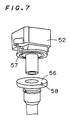
- Referring to Figs. 6 and 7, a
spark plug 51 mounted in the bottom of a plug hole H formed in a cylinder head C and anignition coil 52 fixed on the cylinder head C are electrically connected in a manner to be described below. - A connecting
terminal 53 projecting downwardly from the underside of theignition coil 52 is electrically connected to aterminal 54 of thespark plug 51 which projects upwardly in the cylinder head C through aconductive member 55 such as a single spring, a metal round bar, and a metal cylinder. Aninsulating member 56 covers an outer periphery of theconductive member 55 to extend from the connectingterminal 53 to theterminal 54. - There are two types of insulating
members 56. One type is an insulating member comprised of three members: a cap for covering the range from the connectingterminal 53 to theconductive member 55, a bushing for covering the range from theterminal 54 to theconductive member 55, and a sleeve for covering theconductive member 55 to extend from the cap to the bushing. The other type is an insulating member comprised of the cap, bushing and sleeve which are formed integrally. In either case, the cap or a portion corresponding to the cap is fitted in an upper portion of the plug hole C in such a manner that an upper surface thereof is in intimate contact with the underside of theignition coil 52 and an outer periphery thereof is in intimate contact with an inner peripheral surface of the plug hole H. - A first
air vent hole 57 is formed in the contact portion between the upper surface of the cap or the portion corresponding to the cap and the bottom surface of theignition coil 52 and extends from the outer edge of the contact portion. A secondair vent hole 58 for communication between the firstair vent hole 57 and the interior of the plug hole H is formed in the cap or the portion corresponding to the cap. - When the air in the plug hole H is heated to expand, the expanded amount of air may be escaped through the first and second
air vent holes - The above stated connecting structure presents no significant problem when the cylinder head C is exposed to a small amount of water. However, when the cylinder head C is subjected to high-pressure water, for example, during car washing, water might enter the plug hole H through the first and second
air vent holes - A first aspect of the present invention is directed to a structure for connecting a spark plug and an ignition coil for an internal combustion engine. According to the present invention, the structure comprises: a spark plug mounted in the bottom of a plug hole formed in a cylinder head; an ignition coil mounted on the cylinder head and having a lid portion for closing an upper opening of the plug hole; and a connecting member for electrically and mechanically connecting the ignition coil and the spark plug in the plug hole, the connecting member including an insulating cap between the lid portion of the ignition coil and the cylinder head and in intimate contact with a bottom surface of the lid portion and a periphery of the upper opening of the plug hole, there being a first air vent passage between the insulating cap and the lid portion and in communication with the exterior, the insulating cap having a second air vent passage for communication between the first air vent passage and the interior of the plug hole, there being a large-volume reservoir space between the insulating cap and the lid portion at a position along the first air vent passage and having a cross-sectional area enlarged from the first air vent passage.
- Preferably, according to a second aspect of the present invention, the first air vent passage is defined by a space surrounded by a groove formed in an upper surface of the insulating cap and the bottom surface of the lid portion.
- Preferably, according to a third aspect of the present invention, the first air vent passage is defined by a space surrounded by an upper surface of the insulating cap and a groove formed in the bottom surface of the lid portion.
- Preferably, according to a fourth aspect of the present invention, the first air vent passage is defined by a space surrounded by a groove formed in an upper surface of the insulating cap and a groove formed in the bottom surface of the lid portion.
- Preferably, according to a fifth aspect of the present invention, the reservoir space is defined by a space surrounded by a recess formed in the upper surface of the insulating cap and the bottom surface of the lid portion.
- Preferably, according to a sixth aspect of the present invention, the reservoir space is defined by a space surrounded by the upper surface of the insulating cap and a recess formed in the bottom surface of the lid portion.
- Preferably, according to a seventh aspect of the present invention, the reservoir space is defined by a space surrounded by a recess formed in the upper surface of the insulating cap and a recess formed in the bottom surface of the lid portion.
- According to an eighth aspect of the present invention, the structure comprises: a spark plug mounted in the bottom of a plug hole formed in a cylinder head; an ignition coil including a bar-shaped coil body portion received in the plug hole, a plug connecting portion at the lower end of the coil body portion and connected to the spark plug, and a lid portion at the upper end of the coil body portion and located exteriorly of the plug hole; and an annular rubber member provided between the lid portion of the ignition coil and the cylinder head and in intimate contact with a bottom surface of the lid portion and a periphery of an upper opening of the plug hole, there being a first air vent passage between the annular rubber member and the lid portion and in communication with the exterior, the annular rubber member having a second air vent passage for communication between the first air vent passage and the interior of the plug hole, there being a large-volume reservoir space between the annular rubber member and the lid portion at a position along the first air vent passage and having a cross-sectional area enlarged from the first air vent passage.
- Preferably, according to a ninth aspect of the present invention, the first air vent passage is defined by a space surrounded by a groove formed in an upper surface of the annular rubber member and the bottom surface of the lid portion.
- Preferably, according to a tenth aspect of the present invention, the reservoir space is defined by a space surrounded by a recess formed in the upper surface of the annular rubber member and the bottom surface of the lid portion.
- Preferably, according to an eleventh aspect of the present invention, the lid portion of the ignition coil includes a fixing stay for fixing the ignition coil to the cylinder head, and an electrical connector for connecting a signalling line from an ignition controller to the ignition coil; and an end of the first air vent passage which is open to the exterior is located under the fixing stay or the electrical connector.
- Preferably, according to a twelfth aspect of the present invention, the annular rubber member and the ignition coil include a mechanism for preventing the annular rubber member from rotating relative to the ignition coil.
- Preferably, according to a thirteenth aspect of the present invention, the annular rubber member is prevented from rotating relative to the ignition coil by bringing a projection formed on an outer peripheral surface of the coil body portion into engagement with a recess formed in an inner peripheral surface of the annular rubber member.
- In the structure for connecting the ignition coil and the spark plug as above constructed, when the cylinder head is subjected to high-pressure water, the reservoir space at a position along the first air vent passage stores water from the first air vent passage therein to limit the force of the water. Thus it is difficult and it takes much time for water to reach the plug hole, and the entry of water into the plug hole is effectively prevented.
- The provision of the reservoir space in the cap or ignition coil is effective in reducing the weight of the structure itself.
- It is therefore an object of the present invention to provide a structure for connecting an ignition coil and a spark plug which prevents water from entering a plug hole through an air vent passage when a cylinder head is subjected to high-pressure water.
- These and other objects, features, aspects and advantages of the present invention will become more apparent from the following detailed description of the present invention when taken in conjunction with the accompanying drawings.
-
- Fig. 1 is a fragmentary cross-sectional view of a first preferred embodiment according to the present invention;
- Fig. 2 is a cross-sectional view of an insulating member of the first preferred embodiment;
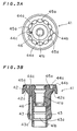
- Figs. 3A and 3B illustrate a cap of the first preferred embodiment;
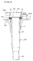
- Fig. 4 is a fragmentary cross-sectional view of a second preferred embodiment according to the present invention;
- Fig. 5 is a plan view of an annular rubber member of the second preferred embodiment;
- Fig. 6 is a fragmentary cross-sectional view of the background art; and
- Fig. 7 is an exploded perspective view of the details of an ignition coil and a cap portion of the background art.
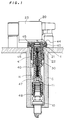
- Preferred embodiments according to the present invention will now be described with reference to the drawings. Referring to Fig. 1, a
spark plug 10 is fixed in the bottom of a plug hole H formed in a cylinder head C so that aterminal portion 11 projects upwardly. Anignition coil 20 is mounted on the opening periphery of the plug hole H of the cylinder head C so that a high-tension tower 21 having a connectingterminal 22 projects from a bottom surface of anignition coil body 23 toward the interior of the plug hole H. Theignition coil 20 includes a disc portion serving as a lid portion. - The
terminal portion 11 of thespark plug 10 is connected to the connectingterminal 22 of theignition coil 20 through acoil spring 30 serving as a conductive member. Thecoil spring 30 is covered with aninsulating member 40 extending from theterminal portion 11 to the high-tension tower 21. - As shown in Figs. 1 and 2, the
insulating member 40 comprises asleeve 47 receiving thecoil spring 30 for covering theterminal portion 11 of thespark plug 10, acap 41 for covering the range from the high-tension tower 21 of theignition coil 20 to an upper portion of thesleeve 47, and abushing 48 mounted to thesleeve 47 from therebelow for covering the inner and outer surfaces of a lower portion of thesleeve 47. Thesleeve 47,cap 41 and bushing 48 are made of an insulating resin. More specifically, thesleeve 47 is made of a rigid resin, and thecap 41 and bushing 48 are made of rubber. - Referring to Figs. 3A and 3B, the
cap 41 includes, in its upper end portion, an outwardly extendingcollar portion 42 having an upper surface in intimate contact with a bottom surface of the disc portion of theignition coil body 23. The lower surface of thecollar portion 42 is in intimate contact with the opening periphery of the plug hole H and has agroove 42a formed circumferentially and receiving a ledge c formed in the peripheral portion of the plug hole H of the cylinder head C for positioning thecap 41. - The
cap 41 comprises a high-tensiontower receiving portion 41a for receiving the high-tension tower 21 of theignition coil 20, and asleeve receiving portion 41b formed in continuation to the high-tensiontower receiving portion 41a for receiving the upper end portion of thesleeve 47 covering thecoil spring 30. The high-tensiontower receiving portion 41a and thesleeve receiving portion 41b have inner surface configurations corresponding respectively to the outer surface configurations of the high-tension tower 21 andsleeve 47. A lower outer peripheral surface of thecap 41 has abump portion 43 raised outwardly so that an outer surface of thebump portion 43 is in intimate contact with the inner peripheral surface of the plug hole H when thecap 41 is fitted in the plug hole H. Thebump portion 43 has acircumferential groove 43a formed throughout the entire circumference for ease of fitting in the plug hole H. - A
circumferential groove 44a and acommunication groove 44b extending from thecircumferential groove 44a to the outer edge of thecollar portion 42 are formed in the upper surface of thecollar portion 42. A plurality ofrecesses 45a which are wider and deeper than thecircumferential groove 44a are formed in circumferentially spaced apart relation along thecircumferential groove 44a. Acommunication groove 44c extends radially inwardly from one of therecesses 45a. - Thus, as shown in Fig. 1, the
circumferential groove 44a andcommunication grooves ignition coil body 23 which is in intimate contact with the upper surface of thecollar portion 42 define a firstair vent hole 44 serving as a first air vent passage, and therecesses 45a and the bottom surface of theignition coil body 23 definereservoir spaces 45 in circumferential positions along theair vent hole 44. - The
cap 41 has a secondair vent hole 46 as a second air vent passage extending from a bottom surface of thecommunication groove 44c and in communication with thecircumferential groove 43a formed in thebump portion 43. With thecap 41 fitted in the plug hole H, excess air in the plug hole H is discharged out of the plug hole H through the first and secondair vent holes - In the structure for connecting the ignition coil and spark plug as above constructed, water might enter the first
air vent hole 44 when the cylinder head C and theignition coil 20 are subjected to high-pressure water. However, the water which has entered the firstair vent hole 44 is stored in thereservoir spaces 45 at circumferential positions along the firstair vent hole 44 to provide a limited force. Thus it is difficult and it takes much time for water to reach the secondair vent hole 46. - Therefore, when the cylinder head C and
ignition coil 20 are subjected to high-pressure water, there is little likelihood that water enters the plug hole H, and watertight performance is improved. For improvement in watertight performance, it is important to provide the air vent passage which is partially enlarged in cross section and to capture waterdrops in the enlarged spaces as in the first preferred embodiment. It is, in particular, significant to provide thereservoir spaces 45 having a cross-sectional area sufficiently greater than the air vent passage in the direction of water flow. - When the
cap 41 is positioned by fitting the ledge c formed on the peripheral portion of the plug hole H of the cylinder head C into thegroove 42a formed in thecollar portion 42 of thecap 41 as in the first preferred embodiment, thereservoir spaces 45 function as a relief of the synthetic resin of thecollar portion 42 compressed between the bottom surface of theignition coil body 23 and the ledge c. - In the first preferred embodiment, the first
air vent hole 44 andreservoir spaces 45 are defined by thecircumferential groove 44a,communication grooves recesses 45a formed in the upper surface of thecap 41 and the flat bottom surface of theignition coil body 23 as above stated. Conversely, the firstair vent hole 44 andreservoir spaces 45 may be defined by similar grooves and recesses formed in the bottom surface of theignition coil body 23 and the flat upper surface of thecap 41. Alternatively, the firstair vent hole 44 andreservoir spaces 45 may be defined by the combination of corresponding grooves and recesses formed in both of the upper surface of thecap 41 and the bottom surface of theignition coil body 23. - The conductive member employs the
coil spring 30 in the first preferred embodiment but is not limited thereto. For example, a metal round bar, a metal cylinder or a combination thereof with a coil spring may be used as the conductive member. The insulating member of the first preferred embodiment comprises three members: thecap 41, thesleeve 47, and thebushing 48. However, thecap 41,sleeve 47 andbushing 48 may be formed integrally. - Figs. 4 and 5 illustrate a second preferred embodiment according to the present invention. Described in the first preferred embodiment is the structure for connecting the
spark plug 10 and theignition coil 20 of the type located exteriorly of the plug hole H formed in the cylinder head C. Description will be given on a structure for connecting the spark plug and anignition coil 50 of the type located within the plug hole H in the second preferred embodiment. - Although not shown, the spark plug is fixed in the bottom of the plug hole H formed in the cylinder head C so that the terminal portion thereof projects upwardly as in the first preferred embodiment.
- Referring to Fig. 4, the
ignition coil 50 comprises acoil body portion 51 received in the plug hole H, aplug connecting portion 52 at the lower end of thecoil body portion 51 and connected to the terminal portion of the spark plug, and alid portion 53 at the upper end of thecoil body portion 51 and extending in the form of an umbrella. - The
coil body portion 51 is bar-shaped so as to be received in the plug hole H, and contains a magnetic core, a primary coil, and a secondary coil in the portion indicated by the broken lines of Fig. 4. - The
lid portion 53 is located exteriorly of the plug hole H as shown in Fig. 4 and includes anelectrical connector 53a for connecting a signalling line (not shown) from an ignition controller to theignition coil 50, and a fixingstay 53b for fixing theignition coil 50 to the cylinder head C. Theelectrical connector 53a and the fixingstay 53b project in opposite directions. - An
annular rubber member 60 is fitted on thecoil body portion 51 in intimate contact therewith between thelid portion 53 of theignition coil 50 and the cylinder head C and acts as a watertight member. The upper and lower surfaces of theannular rubber member 60 are adapted to closely contact a lower surface of thelid portion 53 and an upper surface of the cylinder head C, respectively. - Referring to Fig. 5, a
circumferential groove 61a and acommunication groove 61b extending form thecircumferential groove 61a to the outer edge are formed in the upper surface of theannular rubber member 60. A plurality ofrecesses 62a which are wider and deeper than thecircumferential groove 61a are formed in circumferentially spaced apart relation along thecircumferential groove 61a. Acommunication groove 61c extends radially inwardly from one of therecesses 62a. - Thus, as shown in Fig. 4, the
circumferential groove 61a andcommunication grooves lid portion 53 which is in intimate contact with the upper surface of theannular rubber member 60 define a firstair vent hole 61 serving as an air vent passage, and therecesses 62a and the bottom surface of thelid portion 53 definereservoir spaces 62 in circumferential positions along theair vent hole 61. - A
vertical groove 63a in communication with an end of thecommunication groove 61c is formed in an inner peripheral surface of theannular rubber member 60. Thevertical groove 63a and the outer peripheral surface of thecoil body portion 51 which is in intimate contact with the inner peripheral surface of theannular rubber member 60 define a secondair vent hole 63 in communication with the firstair vent hole 61 and the interior of the plug hole H. - A
recess 64 is formed in the inner peripheral surface of theannular rubber member 60 to engage a projection (not shown) formed on the outer peripheral surface of thecoil body portion 51, preventing theannular rubber member 60 from rotating relative to theignition coil 50 fixed to the cylinder head C. Therecess 64 is located so that an end of the firstair vent hole 61 which is open to the exterior is located under the fixingstay 53b of the lid portion 53 (Fig. 4). - The end of the first
air vent hole 61 which is open to the exterior is located under the fixingstay 53b in the second preferred embodiment, but the present invention is not limited thereto. For example, therecess 64 may be located so that the end of the firstair vent hole 61 which is open to the exterior is located under theelectrical connector 53a. - In the second preferred embodiment, the second
air vent hole 63 is defined by thevertical groove 63a formed in theannular rubber member 60 and the outer peripheral surface of thecoil body portion 51. Like the first preferred embodiment, the secondair vent hole 63 may be formed directly in theannular rubber member 60. - In the structure for connecting the
ignition coil 50 and the spark plug as above constructed, thecoil body portion 51 is received in the plug hole H. Thus, when the end of the firstair vent hole 61 which is open to the exterior must be located in close proximity to the upper surface of the cylinder head C, the reservoir spaces formed in circumferential positions along the firstair vent hole 61 may capture the water which has entered the firstair vent hole 61 to prevent water from entering the plug hole H. Further, since the end of the firstair vent hole 61 which is open to the exterior is located under the fixingstay 53b orelectrical connector 53a of thelid portion 53 as above described, the end of the firstair vent hole 61 which is open to the exterior is prevented from being exposed to water directly. This further reduces the amount of water which enters the firstair vent hole 61. - While the invention has been described in detail, the foregoing description is in all aspects illustrative and not restrictive. It is understood that numerous other modifications and variations can be devised without departing from the scope of the invention.
Claims (13)
- A structure for connecting a spark plug and an ignition coil for an internal combustion engine, comprising:
a spark plug mounted in the bottom of a plug hole formed in a cylinder head;
an ignition coil mounted on said cylinder head and having a lid portion for closing an upper opening of said plug hole; and
a connecting member for electrically and mechanically connecting said ignition coil and said spark plug in said plug hole,
said connecting member including
an insulating cap provided between said lid portion of said ignition coil and said cylinder head and in intimate contact with a bottom surface of said lid portion and a periphery of the upper opening of said plug hole,
there being a first air vent passage between said insulating cap and said lid portion and in communication with the exterior,
said insulating cap having a second air vent passage for communication between said first air vent passage and the interior of said plug hole,
there being a large-volume reservoir space between said insulating cap and said lid portion at a position along said first air vent passage and having a cross-sectional area enlarged from said first air vent passage. - The structure of claim 1,
wherein said first air vent passage is defined by a space surrounded by a groove formed in an upper surface of said insulating cap and the bottom surface of said lid portion. - The structure of claim 1,
wherein said first air vent passage is defined by a space surrounded by an upper surface of said insulating cap and a groove formed in the bottom surface of said lid portion. - The structure of claim 1,
wherein said first air vent passage is defined by a space surrounded by a groove formed in an upper surface of said insulating cap and a groove formed in the bottom surface of said lid portion. - The structure of claim 2, 3, or 4,
wherein said reservoir space is defined by a space surrounded by a recess formed in the upper surface of said insulating cap and the bottom surface of said lid portion. - The structure of claim 2, 3, or 4,
wherein said reservoir space is defined by a space surrounded by the upper surface of said insulating cap and a recess formed in the bottom surface of said lid portion. - The structure of claim 2, 3, or 4,
wherein said reservoir space is defined by a space surrounded by a recess formed in the upper surface of said insulating cap and a recess formed in the bottom surface of said lid portion. - A structure for connecting a spark plug and an ignition coil for an internal combustion engine, comprising:
a spark plug mounted in the bottom of a plug hole formed in a cylinder head;
an ignition coil including a bar-shaped coil body portion received in said plug hole, a plug connecting portion at the lower end of said coil body portion and connected to said spark plug, and a lid portion at the upper end of said coil body portion and located exteriorly of said plug hole; and
an annular rubber member provided between said lid portion of said ignition coil and said cylinder head and in intimate contact with a bottom surface of said lid portion and a periphery of an upper opening of said plug hole,
there being a first air vent passage between said annular rubber member and said lid portion and in communication with the exterior,
said annular rubber member having a second air vent passage for communication between said first air vent passage and the interior of said plug hole,
there being a large-volume reservoir space between said annular rubber member and said lid portion at a position along said first air vent passage and having a cross-sectional area enlarged from said first air vent passage. - The structure of claim 8,
wherein said first air vent passage is defined by a space surrounded by a groove formed in an upper surface of said annular rubber member and the bottom surface of said lid portion. - The structure of claim 9,
wherein said reservoir space is defined by a space surrounded by a recess formed in the upper surface of said annular rubber member and the bottom surface of said lid portion. - The structure of claim 8,
wherein said lid portion of said ignition coil includes:
a fixing stay for fixing said ignition coil to said cylinder head; and
an electrical connector for connecting a signalling line from an ignition controller to said ignition coil, and
wherein an end of said first air vent passage which is open to the exterior is located under said fixing stay or said electrical connector. - The structure of claim 11,
wherein said annular rubber member and said ignition coil include a mechanism for preventing said annular rubber member from rotating relative to said ignition coil. - The structure of claim 12,
wherein said annular rubber member is prevented from rotating relative to said ignition coil by bringing a projection formed on an outer peripheral surface of said coil body portion into engagement with a recess formed in an inner peripheral surface of said annular rubber member.
Applications Claiming Priority (3)
| Application Number | Priority Date | Filing Date | Title |
|---|---|---|---|
| JP288234/94 | 1994-11-22 | ||
| JP28823494A JP3145880B2 (en) | 1994-11-22 | 1994-11-22 | Connection structure of ignition plug and ignition coil for internal combustion engine |
| JP28823494 | 1994-11-22 |
Publications (3)
| Publication Number | Publication Date |
|---|---|
| EP0713969A2 true EP0713969A2 (en) | 1996-05-29 |
| EP0713969A3 EP0713969A3 (en) | 1997-07-30 |
| EP0713969B1 EP0713969B1 (en) | 1999-09-01 |
Family
ID=17727574
Family Applications (1)
| Application Number | Title | Priority Date | Filing Date |
|---|---|---|---|
| EP95117454A Expired - Lifetime EP0713969B1 (en) | 1994-11-22 | 1995-11-06 | Structure for connecting spark plug and ignition coil for internal combustion engine |
Country Status (6)
| Country | Link |
|---|---|
| US (1) | US5618193A (en) |
| EP (1) | EP0713969B1 (en) |
| JP (1) | JP3145880B2 (en) |
| KR (1) | KR0148527B1 (en) |
| CN (1) | CN1046570C (en) |
| DE (1) | DE69511824T2 (en) |
Cited By (5)
| Publication number | Priority date | Publication date | Assignee | Title |
|---|---|---|---|---|
| DE19624287A1 (en) * | 1995-10-13 | 1997-04-17 | Mitsubishi Electric Corp | Waterproof spark plug opening seal for an internal combustion engine |
| EP1001164A2 (en) * | 1998-11-12 | 2000-05-17 | Bayerische Motoren Werke Aktiengesellschaft | Ignition apparatus for internal combustion engine |
| WO2003052264A1 (en) * | 2001-12-19 | 2003-06-26 | Robert Bosch Gmbh | Ignition device for an internal combustion engine |
| EP1426686A2 (en) * | 2002-11-28 | 2004-06-09 | Ngk Spark Plug Co., Ltd | Glow plug and structure for mounting the same onto cylinder head including plug cap and cable |
| EP1804351A1 (en) * | 2005-12-27 | 2007-07-04 | HONDA MOTOR CO., Ltd. | Plug cap attachment structure |
Families Citing this family (34)
| Publication number | Priority date | Publication date | Assignee | Title |
|---|---|---|---|---|
| US6001932A (en) * | 1995-07-25 | 1999-12-14 | Nippon Mektron, Limited | Acrylic copolymer elastomer, its blend rubber and blend rubber composition |
| DE29614872U1 (en) * | 1996-08-27 | 1998-01-02 | Bosch Gmbh Robert | Ignition coil arrangement for internal combustion engines |
| JP3361704B2 (en) * | 1996-10-25 | 2003-01-07 | 矢崎総業株式会社 | Plug cap for spark plug |
| US5799633A (en) * | 1997-08-08 | 1998-09-01 | Lexington Insulators | Electrical insulator with a duckbill-shaped valve |
| US5944002A (en) * | 1998-04-17 | 1999-08-31 | Cummins Engine Company, Inc. | Self-venting grommet for coil-on-plug |
| US5957706A (en) * | 1998-06-17 | 1999-09-28 | General Motors Corporation | Ignition cable terminal assembly |
| DE69935776T2 (en) | 1998-12-01 | 2007-12-27 | Honda Giken Kogyo K.K. | More cylinder head |
| US6427674B1 (en) | 2001-09-24 | 2002-08-06 | Daimlerchrysler Corporation | Socket coil-on-plug retainer |
| KR100560758B1 (en) * | 2001-12-10 | 2006-03-13 | 한국델파이주식회사 | Ignition coil for vehicle |
| US6609508B2 (en) * | 2002-01-04 | 2003-08-26 | Visteon Global Technologies, Inc. | Releasable retaining clip for ignition coil assembly |
| KR100477063B1 (en) * | 2002-11-14 | 2005-03-17 | 주식회사 포스코 | Pulverized coal injection lance having position control function |
| DE102004039036B4 (en) * | 2003-08-12 | 2014-11-13 | Denso Corporation | Ignition device for an internal combustion engine |
| DE202004015917U1 (en) * | 2004-10-13 | 2005-01-20 | Virchow, Florian | Contacting element for electrically contacting components |
| JP4209407B2 (en) * | 2005-05-19 | 2009-01-14 | 三菱電機株式会社 | Ignition device for internal combustion engine |
| JP3891208B2 (en) * | 2005-07-12 | 2007-03-14 | 株式会社デンソー | Ignition coil and manufacturing method thereof |
| JP2007162645A (en) * | 2005-12-16 | 2007-06-28 | Hanshin Electric Co Ltd | Ignition coil for internal combustion engine |
| JP2008034561A (en) * | 2006-07-27 | 2008-02-14 | Denso Corp | Ignition coil |
| JP2009121352A (en) * | 2007-11-15 | 2009-06-04 | Hanshin Electric Co Ltd | Ignition coil protector for internal combustion engine |
| WO2010081153A2 (en) * | 2009-01-12 | 2010-07-15 | Federal-Mogul Ignition Company | Igniter system for igniting fuel |
| US8151781B2 (en) | 2009-01-12 | 2012-04-10 | Federal-Mogul Ignition Company | Flexible ignitor assembly for air/fuel mixture and method of construction thereof |
| JP5430255B2 (en) * | 2009-07-02 | 2014-02-26 | ダイヤモンド電機株式会社 | Ignition coil |
| CN101604821B (en) * | 2009-07-11 | 2012-07-04 | 中煤牡丹江焦化有限责任公司 | Sparking plug for combined type gas internal combustion engine |
| JP4892599B2 (en) * | 2009-10-09 | 2012-03-07 | 東洋電装株式会社 | Engine plug hole waterproof device |
| JP5175879B2 (en) * | 2010-02-24 | 2013-04-03 | 日本特殊陶業株式会社 | Plug cap |
| US8061338B1 (en) * | 2010-08-05 | 2011-11-22 | Ford Global Technologies, Llc | Ignition coil to spark plug mating apparatus |
| CN102003322A (en) * | 2010-11-04 | 2011-04-06 | 联合汽车电子有限公司 | Ignition coil housing |
| JP5997689B2 (en) * | 2011-03-04 | 2016-09-28 | 日立オートモティブシステムズ株式会社 | Ignition coil for internal combustion engine |
| JP5740258B2 (en) * | 2011-09-08 | 2015-06-24 | 株式会社クボタ | Spark ignition engine |
| CN102900584A (en) * | 2012-10-30 | 2013-01-30 | 天津市新阳电子有限公司 | Automobile ignition coil high voltage output assembly provided with rigid bush |
| US9281663B2 (en) | 2013-04-26 | 2016-03-08 | Howard Johnson | General aviation igniter cable assembly |
| JP6375882B2 (en) * | 2014-11-11 | 2018-08-22 | 株式会社デンソー | Ignition coil for internal combustion engine |
| DE102018108292B4 (en) * | 2017-11-17 | 2023-05-11 | Borgwarner Ludwigsburg Gmbh | Connector for connecting an ignition coil to a spark plug and protective tube for a connector |
| DE102019123721B4 (en) * | 2019-09-04 | 2021-09-30 | Man Energy Solutions Se | Rocker arm cover with spark plug contacts for an internal combustion engine |
| CN112648099B (en) * | 2019-10-11 | 2022-07-22 | 广州汽车集团股份有限公司 | Cylinder head assembly and engine comprising same |
Family Cites Families (12)
| Publication number | Priority date | Publication date | Assignee | Title |
|---|---|---|---|---|
| FR725446A (en) * | 1930-11-14 | 1932-05-12 | Bosch Robert | Protective cap for spark plugs |
| US1979999A (en) * | 1934-01-20 | 1934-11-06 | Gen Motors Corp | Spark plug for high compression engines |
| US2686509A (en) * | 1951-12-20 | 1954-08-17 | Chrysler Corp | Spark plug and ignition lead wire protective system |
| JPS5999067A (en) * | 1982-11-29 | 1984-06-07 | Hitachi Ltd | Knock control system |
| CA1281953C (en) * | 1984-09-27 | 1991-03-26 | Yoshiki Yano | Plug cap apparatus |
| JPH01147161A (en) * | 1987-12-02 | 1989-06-08 | Sanshin Ind Co Ltd | Ignition device for internal combustion engine |
| ES2057622T3 (en) * | 1990-03-08 | 1994-10-16 | Nippon Denso Co | IGNITION COIL FOR AN INTERNAL COMBUSTION ENGINE. |
| US5215475A (en) * | 1992-07-02 | 1993-06-01 | Amerace Corporation | Devices for use with high voltage system components for the safe expulsion of conductive moisture within such components |
| US5377640A (en) * | 1992-07-23 | 1995-01-03 | Sumitomo Wiring Systems, Ltd. | Plug cap device |
| JP2576071B2 (en) * | 1992-08-06 | 1997-01-29 | 株式会社デンソー | Ignition coil device for internal combustion engine |
| JP3131669B2 (en) * | 1992-11-10 | 2001-02-05 | 本田技研工業株式会社 | Spark plug cap integrated with ignition coil |
| JP2602711Y2 (en) * | 1993-10-13 | 2000-01-24 | 矢崎総業株式会社 | Rain cover for spark plug mounting hole |
-
1994
- 1994-11-22 JP JP28823494A patent/JP3145880B2/en not_active Expired - Lifetime
-
1995
- 1995-11-06 DE DE69511824T patent/DE69511824T2/en not_active Expired - Lifetime
- 1995-11-06 EP EP95117454A patent/EP0713969B1/en not_active Expired - Lifetime
- 1995-11-13 US US08/555,010 patent/US5618193A/en not_active Expired - Lifetime
- 1995-11-15 KR KR1019950041486A patent/KR0148527B1/en active IP Right Grant
- 1995-11-22 CN CN95118854A patent/CN1046570C/en not_active Expired - Lifetime
Non-Patent Citations (1)
| Title |
|---|
| None |
Cited By (8)
| Publication number | Priority date | Publication date | Assignee | Title |
|---|---|---|---|---|
| DE19624287A1 (en) * | 1995-10-13 | 1997-04-17 | Mitsubishi Electric Corp | Waterproof spark plug opening seal for an internal combustion engine |
| DE19624287C2 (en) * | 1995-10-13 | 1999-03-11 | Mitsubishi Electric Corp | Ignitor for an internal combustion engine |
| EP1001164A2 (en) * | 1998-11-12 | 2000-05-17 | Bayerische Motoren Werke Aktiengesellschaft | Ignition apparatus for internal combustion engine |
| EP1001164A3 (en) * | 1998-11-12 | 2002-08-07 | Bayerische Motoren Werke Aktiengesellschaft | Ignition apparatus for internal combustion engine |
| WO2003052264A1 (en) * | 2001-12-19 | 2003-06-26 | Robert Bosch Gmbh | Ignition device for an internal combustion engine |
| EP1426686A2 (en) * | 2002-11-28 | 2004-06-09 | Ngk Spark Plug Co., Ltd | Glow plug and structure for mounting the same onto cylinder head including plug cap and cable |
| EP1426686A3 (en) * | 2002-11-28 | 2004-07-28 | Ngk Spark Plug Co., Ltd | Glow plug and structure for mounting the same onto cylinder head including plug cap and cable |
| EP1804351A1 (en) * | 2005-12-27 | 2007-07-04 | HONDA MOTOR CO., Ltd. | Plug cap attachment structure |
Also Published As
| Publication number | Publication date |
|---|---|
| EP0713969A3 (en) | 1997-07-30 |
| CN1046570C (en) | 1999-11-17 |
| EP0713969B1 (en) | 1999-09-01 |
| KR960018224A (en) | 1996-06-17 |
| US5618193A (en) | 1997-04-08 |
| JPH08144917A (en) | 1996-06-04 |
| DE69511824T2 (en) | 2000-05-25 |
| CN1130721A (en) | 1996-09-11 |
| DE69511824D1 (en) | 1999-10-07 |
| JP3145880B2 (en) | 2001-03-12 |
| KR0148527B1 (en) | 1998-11-02 |
Similar Documents
| Publication | Publication Date | Title |
|---|---|---|
| US5618193A (en) | Structure for connecting spark plug and ignition coil for internal combustion | |
| US5537983A (en) | Ignition system for internal combustion engine | |
| EP0509454B1 (en) | Cap for a high-tension cable terminal for use in an automobile engine | |
| US5170767A (en) | Ignition coil for internal combustion engine | |
| GB2308753A (en) | Cap type connector assembly for high voltage cable | |
| US5771870A (en) | Ignition coil for an internal combustion engine | |
| CA2172585C (en) | Automotive ignition coil assembly | |
| US5662095A (en) | Plug cap for insertion into a bore | |
| US4515245A (en) | Oil filler extension | |
| US7107819B2 (en) | Pressure sensor unit having a ring-like pressure sensing element | |
| JP2569743B2 (en) | Ignition coil plug cap | |
| US5755581A (en) | Plug cap for spark plug | |
| JPH08106932A (en) | Plug cap for spark plug | |
| JP3361697B2 (en) | Plug cap for spark plug | |
| JP3389011B2 (en) | Plug cap for spark plug | |
| JP4522597B2 (en) | Pressure sensor unit | |
| JP3954299B2 (en) | Plug cap for spark plug | |
| CN100480506C (en) | Ignition device of engine | |
| JPH08335488A (en) | Plug cap for ignition plug | |
| JPH03264776A (en) | Ignition coil for internal combustion engine | |
| JPH0211982Y2 (en) | ||
| JPH0423296Y2 (en) | ||
| JP2593300Y2 (en) | Ignition device for internal combustion engine | |
| JP3447039B2 (en) | Ignition device assembly structure | |
| JP3465356B2 (en) | Spark plug joints for internal combustion engines |
Legal Events
| Date | Code | Title | Description |
|---|---|---|---|
| PUAI | Public reference made under article 153(3) epc to a published international application that has entered the european phase |
Free format text: ORIGINAL CODE: 0009012 |
|
| AK | Designated contracting states |
Kind code of ref document: A2 Designated state(s): DE FR GB |
|
| PUAL | Search report despatched |
Free format text: ORIGINAL CODE: 0009013 |
|
| 17P | Request for examination filed |
Effective date: 19970528 |
|
| AK | Designated contracting states |
Kind code of ref document: A3 Designated state(s): DE FR GB |
|
| RHK1 | Main classification (correction) |
Ipc: F02P 13/00 |
|
| RAP1 | Party data changed (applicant data changed or rights of an application transferred) |
Owner name: DENSO CORPORATION Owner name: SUMITOMO WIRING SYSTEMS, LTD. |
|
| 17Q | First examination report despatched |
Effective date: 19980605 |
|
| GRAG | Despatch of communication of intention to grant |
Free format text: ORIGINAL CODE: EPIDOS AGRA |
|
| GRAG | Despatch of communication of intention to grant |
Free format text: ORIGINAL CODE: EPIDOS AGRA |
|
| GRAH | Despatch of communication of intention to grant a patent |
Free format text: ORIGINAL CODE: EPIDOS IGRA |
|
| GRAH | Despatch of communication of intention to grant a patent |
Free format text: ORIGINAL CODE: EPIDOS IGRA |
|
| GRAA | (expected) grant |
Free format text: ORIGINAL CODE: 0009210 |
|
| AK | Designated contracting states |
Kind code of ref document: B1 Designated state(s): DE FR GB |
|
| REF | Corresponds to: |
Ref document number: 69511824 Country of ref document: DE Date of ref document: 19991007 |
|
| ET | Fr: translation filed | ||
| PLBE | No opposition filed within time limit |
Free format text: ORIGINAL CODE: 0009261 |
|
| STAA | Information on the status of an ep patent application or granted ep patent |
Free format text: STATUS: NO OPPOSITION FILED WITHIN TIME LIMIT |
|
| 26N | No opposition filed | ||
| REG | Reference to a national code |
Ref country code: GB Ref legal event code: IF02 |
|
| PGFP | Annual fee paid to national office [announced via postgrant information from national office to epo] |
Ref country code: FR Payment date: 20141110 Year of fee payment: 20 Ref country code: DE Payment date: 20141029 Year of fee payment: 20 Ref country code: GB Payment date: 20141105 Year of fee payment: 20 |
|
| REG | Reference to a national code |
Ref country code: DE Ref legal event code: R071 Ref document number: 69511824 Country of ref document: DE |
|
| REG | Reference to a national code |
Ref country code: GB Ref legal event code: PE20 Expiry date: 20151105 |
|
| PG25 | Lapsed in a contracting state [announced via postgrant information from national office to epo] |
Ref country code: GB Free format text: LAPSE BECAUSE OF EXPIRATION OF PROTECTION Effective date: 20151105 |