EP0713654B1 - Processing high-pressure liquid material - Google Patents
Processing high-pressure liquid material Download PDFInfo
- Publication number
- EP0713654B1 EP0713654B1 EP95308131A EP95308131A EP0713654B1 EP 0713654 B1 EP0713654 B1 EP 0713654B1 EP 95308131 A EP95308131 A EP 95308131A EP 95308131 A EP95308131 A EP 95308131A EP 0713654 B1 EP0713654 B1 EP 0713654B1
- Authority
- EP
- European Patent Office
- Prior art keywords
- working fluid
- pressure
- working
- pressure chamber
- cylinder devices
- Prior art date
- Legal status (The legal status is an assumption and is not a legal conclusion. Google has not performed a legal analysis and makes no representation as to the accuracy of the status listed.)
- Expired - Lifetime
Links
- 239000011344 liquid material Substances 0.000 title claims description 120
- 238000012545 processing Methods 0.000 title claims description 32
- 239000012530 fluid Substances 0.000 claims description 195
- 238000000034 method Methods 0.000 claims description 16
- 238000004891 communication Methods 0.000 claims description 5
- 239000007788 liquid Substances 0.000 claims description 3
- 230000001105 regulatory effect Effects 0.000 claims 2
- 230000001276 controlling effect Effects 0.000 claims 1
- 238000007599 discharging Methods 0.000 description 10
- 238000010586 diagram Methods 0.000 description 7
- 239000000047 product Substances 0.000 description 7
- 238000012986 modification Methods 0.000 description 5
- 230000004048 modification Effects 0.000 description 5
- 230000035939 shock Effects 0.000 description 5
- 238000009434 installation Methods 0.000 description 3
- 230000002159 abnormal effect Effects 0.000 description 2
- 230000000694 effects Effects 0.000 description 2
- 230000009969 flowable effect Effects 0.000 description 2
- 239000000463 material Substances 0.000 description 2
- 239000013589 supplement Substances 0.000 description 2
- 238000001514 detection method Methods 0.000 description 1
- 239000000796 flavoring agent Substances 0.000 description 1
- 235000019634 flavors Nutrition 0.000 description 1
- 230000004941 influx Effects 0.000 description 1
- 239000007787 solid Substances 0.000 description 1
- 238000012546 transfer Methods 0.000 description 1
- 238000011144 upstream manufacturing Methods 0.000 description 1
Images


Classifications
-
- A—HUMAN NECESSITIES
- A23—FOODS OR FOODSTUFFS; TREATMENT THEREOF, NOT COVERED BY OTHER CLASSES
- A23B—PRESERVATION OF FOODS, FOODSTUFFS OR NON-ALCOHOLIC BEVERAGES; CHEMICAL RIPENING OF FRUIT OR VEGETABLES
- A23B2/00—Preservation of foods or foodstuffs, in general
- A23B2/10—Preservation of foods or foodstuffs, in general by treatment with pressure variation, shock, acceleration or shear stress
- A23B2/103—Preservation of foods or foodstuffs, in general by treatment with pressure variation, shock, acceleration or shear stress using sub- or super-atmospheric pressures, or pressure variations transmitted by a liquid or gas
-
- Y—GENERAL TAGGING OF NEW TECHNOLOGICAL DEVELOPMENTS; GENERAL TAGGING OF CROSS-SECTIONAL TECHNOLOGIES SPANNING OVER SEVERAL SECTIONS OF THE IPC; TECHNICAL SUBJECTS COVERED BY FORMER USPC CROSS-REFERENCE ART COLLECTIONS [XRACs] AND DIGESTS
- Y02—TECHNOLOGIES OR APPLICATIONS FOR MITIGATION OR ADAPTATION AGAINST CLIMATE CHANGE
- Y02P—CLIMATE CHANGE MITIGATION TECHNOLOGIES IN THE PRODUCTION OR PROCESSING OF GOODS
- Y02P60/00—Technologies relating to agriculture, livestock or agroalimentary industries
- Y02P60/80—Food processing, e.g. use of renewable energies or variable speed drives in handling, conveying or stacking
- Y02P60/85—Food storage or conservation, e.g. cooling or drying
-
- Y—GENERAL TAGGING OF NEW TECHNOLOGICAL DEVELOPMENTS; GENERAL TAGGING OF CROSS-SECTIONAL TECHNOLOGIES SPANNING OVER SEVERAL SECTIONS OF THE IPC; TECHNICAL SUBJECTS COVERED BY FORMER USPC CROSS-REFERENCE ART COLLECTIONS [XRACs] AND DIGESTS
- Y10—TECHNICAL SUBJECTS COVERED BY FORMER USPC
- Y10T—TECHNICAL SUBJECTS COVERED BY FORMER US CLASSIFICATION
- Y10T436/00—Chemistry: analytical and immunological testing
- Y10T436/25—Chemistry: analytical and immunological testing including sample preparation
- Y10T436/2575—Volumetric liquid transfer
Definitions
- the present invention relates to a method of and an apparatus for processing a high-pressure liquid material.
- the disclosed apparatus has a high-pressure vessel for processing a liquid material under a high pressure therein, a pressurizing means for introducing the liquid material into the high-pressure vessel and pressurizing the liquid material in the high-pressure vessel, and a depressurizing means for drawing the processed liquid material from the high-pressure vessel, depressurizing the liquid material, and discharging the liquid material out of a system.
- the apparatus is capable of continuously processing the liquid material under a predetermined pressure, and depressurizing and discharging the processed liquid material out of the system.
- the depressurizing means comprises a pair of coaxially positioned pressure chambers for receiving the liquid material that has been processed.
- the liquid material is drawn into the pressure chambers (suction mode), depressurized in the pressure chambers (depressurization mode), and discharged from the pressure chambers (discharge mode) by a pair of respective plungers actuatable in synchronism with each other.
- the plungers are controlled by a double-acting hydraulic cylinder assembly which has a pair of working pressure chambers supplied with a working oil from a hydraulic unit.
- the depressurizing means is elongate and requires a large installation space.
- the volume of one of the pressure chambers of the depressurizing means is uniquely determined by the volume of the other pressure chamber thereof.
- the depressurizing means lacks a sufficient degree of freedom of operation. Specifically, no sufficient flexibility is given to the layout of the working pressure chambers, the individual volumes thereof, and the pressure control thereof, and the pressure of the working oil discharged in the suction and depressurization modes cannot be utilized as an energy for actuating the pressure chambers in the discharge mode.
- the working pressure chambers cannot freely be supplied with the working oil from the hydraulic unit and cannot freely discharge the working oil by controlling shutoff valves. Therefore, it is impossible to adjust any times for which to carry out the suction mode, the depressurization mode, and the discharge mode. For example, it is not possible to adjust times for which to carry out the suction and depressurization modes while the discharge mode is being continuously carried out for a certain period of time.
- the working oil from the hydraulic unit is used only to apply a back pressure after the liquid material has been introduced under a high pressure for reducing the rate of the discharge mode or the suction and depressurization modes. Stated otherwise, inasmuch as no pressurization is effected to apply a back pressure which would otherwise substantially counterbalance the high pressure of the liquid material before the suction mode, a pressure shock is imposed on pipes and various valves upon start of the suction mode, lowering the durability of these components.
- the invention provides an apparatus for processing a high-pressure liquid material, comprising:
- the invention provides a method of processing a high-pressure liquid material, comprising the steps of:
- the present invention provides a method of and an apparatus for processing a high-pressure liquid material wherein less energy is required to operate the apparatus, the apparatus requiring a reduced space for its installation.
- At least a portion of the working fluid discharged from the working pressure chamber of one of the cylinder devices which is operating in said suction mode and the working pressure chamber of another one of said cylinder devices which is operating in said depressurization mode is supplied to the working pressure chamber of another one of said cylinder devices which is operating in said discharge mode to assist it to perform the discharge mode.
- the working fluid control system may supply the working fluid discharged from the working pressure chamber of one of said cylinder devices which is operating in the suction mode to the working pressure chamber of another one of said cylinder devices which has completed the discharge mode to apply a back pressure to said piston which defines the processing pressure chamber of said other one of said cylinder devices.
- the back pressure is applied in a pressurization mode prior to the suction mode so as to substantially counterbalance the high pressure of the liquid material supplied from the high-pressure vessel. Therefore, when said one of the cylinder devices which has completed the discharge mode starts to draw the liquid material in the suction mode, no pressure shocks are imposed on pipes and various pipes upon an influx of the liquid material from the high-pressure vessel into the processing pressure chamber of said one of the cylinder devices. Therefore, these components are protected against damage for high durability, and the liquid material is prevented from flowing unduly rapidly through shutoff valves.
- the working fluid control system may comprise a working fluid tank containing the working fluid, a pump for supplying the working fluid from said working fluid tank selectively to the working pressure chambers of said cylinder devices, and means for supplying the working fluid from said working fluid tank to the working pressure chamber of one of said cylinder devices which is operating in the discharge mode.
- the working fluid can be supplied from the working fluid tank selectively to the working pressure chamber of any one of the cylinder devices which operates in the discharge mode.
- the cylinder device can reliably operate in the discharge mode, and the depressurizing means and the working fluid control system can be replenished with the working fluid from the working fluid tank by the pump. Consequently, an appropriate amount of working fluid can be maintained in the working fluid control system which can supply the working fluid selectively to and discharge the working fluid selectively from the working pressure chambers of the cylinder devices, for thereby allowing the cylinder devices to operate constantly and reliably in the suction, depressurization, and discharge modes.
- the depressurizing means may have first, second, and third cylinder devices, and said working fluid control system may comprise a first piping for depressurizing and supplying the working fluid from the working pressure chamber of the first cylinder device which is operating in the suction mode to the working pressure chamber of the second cylinder device which is operating in the discharge mode, a second piping for depressurizing and supplying the working fluid from the working pressure chamber of the third cylinder device which is operating in the depressurization mode to the working pressure chamber of the second cylinder device which is operating in the discharge mode, and a third piping for supplying the working fluid from the working pressure chamber of the first cylinder device which is operating in the suction mode to the working pressure chamber of the second cylinder device which has completed the discharge mode.
- the pressurization mode may be carried out prior to the suction mode, using the third piping.
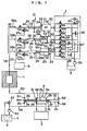
- the apparatus has a high-pressure vessel 1 with a pressurization chamber defined therein.
- the high-pressure vessel 1 is connected at one end thereof to a pressurizing means 2 in the form of a pump through a pipe 50.
- the pressurizing means 2 has a larger-diameter double-acting cylinder 2a and a pair of smaller-diameter cylinders 2b, 2c connected to respective opposite ends of the larger-diameter cylinder 2a.
- a larger-diameter piston 2d is slidably fitted in the larger-diameter cylinder 2a, and a pair of smaller-diameter pistons 2e, 2f is slidably fitted in the respective smaller-diameter cylinders 2b, 2c.
- the pistons 2d, 2e, 2f are coaxially connected to each other by a single piston rod 2g.
- the larger-diameter piston 2d divides the larger-diameter cylinder 2a into second pressure chambers 2j, 2k.
- the smaller-diameter cylinders 2b, 2c have respective air vent holes 2h, 2i defined in rod-end portions thereof.
- the smaller-diameter cylinders 2b, 2c have respective first pressure chambers 2m, 2n defined in cap-end portions thereof which are connected to the pipe 50 through respective check valves 51, 52 which permit a liquid flow from the pressurizing means 2 to the high-pressure vessel 1.
- a liquid material tank 4 contains a liquid material X to be processed, such as a flowable food material, a flowable pharmaceutical material, or the like.
- a pump 53 connected to the liquid material tank 4 operates, the liquid material X contained in the liquid material tank 4 flows into a pipe 54 and is then drawn into one of the first pressure chambers 2m, 2n.
- the first pressure chambers 2m, 2n are connected to the liquid material tank 4 through respective check valves 55, 56 which permit a liquid flow from the liquid material tank 4 to the pressurizing means 2.
- a relief valve 57 is connected to the pipe 54 for limiting a maximum pressure in the pipe 54.
- the high-pressure vessel 1 processes the supplied liquid material X under a high pressure in the pressurization chamber.
- the high-pressure vessel 1 can be supplied with successive amounts of liquid material X in timed relation to suction modes of respective depressurizing devices A, B, C (described below).
- the other end of the high-pressure vessel 1 is connected through a pipe 58 to a depressurizing means 10 which comprises three independently operable depressurizing devices A, B, C connected parallel to each other.
- the depressurizing devices A, B, C comprise respective pressure intensifiers each in the form of a cylinder assembly having a larger-diameter cylinder 21 and a smaller-diameter cylinder 22 connected to one end of the larger-diameter cylinder 21.
- the depressurizing devices A, B, C have respective larger-diameter pistons 23 slidably fitted in the respective larger-diameter cylinders 21 and respective smaller-diameter pistons 24 slidably fitted in the respective smaller-diameter cylinders 22.
- the larger-diameter pistons 23 and the smaller-diameter pistons 24 are coaxially connected to each other by respective piston rods 25.
- the larger-diameter pistons 23 define respective third pressure chambers A1, B1, C1 in cap-end portions of the respective larger-diameter cylinders 21, the third pressure chambers A1, B1, C1 serving as working pressure chambers.
- the smaller-diameter pistons 24 define respective fourth pressure chambers A2, B2, C2 in cap-end portions of the respective smaller-diameter cylinders 22, the fourth pressure chambers A2, B2, C2 serving as pressure chambers for processing the liquid material X.
- the smaller-diameter cylinders 22 have respective air vent holes 22a defined in rod-end portions thereof.
- the larger-diameter cylinders 21 have respective discharge-position limit switches SA for detecting when the larger-diameter pistons 23 have reached a predetermined advanced position, i.e., a left end position in FIG. 1, respective suction-position limit switches SC for detecting when the larger-diameter pistons 23 have reached a predetermined retracted position, i.e., a right position in FIG. 1, and respective depressurization-position limit switches SD for detecting when the larger-diameter pistons 23 have reached a most retracted position, i.e., a right end position in FIG. 1.
- the depressurization-position limit switches SD may be dispensed with, and pressure detectors may be connected to pipes joined to the larger-diameter cylinders 21 for detecting the completion of a depressurization mode for depressurizing the liquid material X based on a detected pressure.
- the suction-position limit switches SC are turned on.
- the depressurizing devices A, B, C finish the suction mode when the liquid material X compressed under a high pressure which has been drawn into the respective fourth pressure chambers A2, B2, C2 is depressurized substantially to the atmospheric pressure, so that the liquid material X is allowed to expand in volume.
- the depressurization-position limit switches SD detect the respective larger-diameter pistons 23 when the liquid material X has been depressurized substantially to the atmospheric pressure.
- Each of the limit switches SA, SC, SD may comprise an analog position detector.
- the pipe 58 connected to the other end of the high-pressure vessel 1 is branched into three branch pipes 58a, 58b, 58c which are connected through respective shutoff valves 11a, 11b, 11c to the respective fourth pressure chambers A2, B2, C2 of the depressurizing devices A, B, C.
- Pipes 27a, 27b, 27c are branched from the respective branch pipes 58a, 58b, 58c at positions between the shutoff valves 11a, 11b, 11c and the fourth pressure chambers A2, B2, C2, and connected through respective shutoff valves 12a, 12b, 12c to a single pipe 27 that is connected to a product tank 6 for containing a product.
- shutoff valves 11a, 11b, 11c and the shutoff valves 12a, 12b, 12c are automatically controlled so as to be selectively opened and closed by a controller (not shown). Under the control of the controller, the shutoff valves 11a, 11b, 11c and the shutoff valves 12a, 12b, 12c are selectively opened and closed to connect the single high-pressure vessel 1 selectively to the fourth pressure chambers A2, B2, C2 and also connect the product tank 6 selectively to the fourth pressure chambers A2, B2, C2.
- the third pressure chambers A1, B1, C1 of the respective depressurizing devices A, B, C are connected to a working fluid control system 7 which can bring any one of the third pressure chambers A1, B1, C1 into communication with one or two of the other third pressure chambers for passing a working fluid, typically working oil under a relatively low pressure, thereto.
- the working fluid control system 7 serves to enable the depressurizing devices A, B, C to successively carry out the suction, depressurization, and discharge modes for drawing, depressurizing, and discharging the liquid material X.
- the working fluid control system 7 comprises a plurality of shutoff valves 41a, 41b, 41c, 42a, 42b, 42c, 43a, 43b, 43c, a variable restrictor 44, a pressure control valve PV, and a relief valve 45 which are connected as shown in FIG. 1.
- the pressure control valve PV comprises a pressure-reducing valve whose pressure setting can be controlled by a pressure controller PC based on an upstream pressure that is detected by a pressure transfer unit PT.
- the working fluid control system 7 has a first piping for supplying the working fluid from one of the third pressure chambers A1, B1, C1 of the respective depressurizing devices A, B, C which carries out the suction mode for drawing the liquid material X, after the working fluid has been depressurized by the pressure control valve PV, to another one of the third pressure chambers B1, C1, A1 of the respective depressurizing devices B, C, A which carries out the discharge mode for discharging the liquid material X, a second piping for supplying the working fluid from one of the third pressure chambers C1, A1, B1 of the respective depressurizing devices C, A, B which carries out the depressurization mode for depressurizing the liquid material X, after the working fluid has been depressurized by the restrictor 44, to another one of the third pressure chambers B1, C1, A1 of the respective depressurizing devices B, C, A which carries out the discharge mode for discharging the liquid material X, and a third piping for supplying the working
- the shutoff valves 42a, 41b, 43c are opened to supply the working fluid from the third pressure chamber A1 through the shutoff valve 42a, the pressure control valve PV, and the shutoff valve 41b to the third pressure chamber B1, and also to supply the working fluid from the third pressure chamber C1 through the shutoff valve 43c, the restrictor 44, and the shutoff valve 41b to the third pressure chamber B1.
- the liquid material X is drawn into the fourth pressure chamber A2, the liquid material X is discharged from the fourth pressure chamber B2 into the product tank 6, and the liquid material X in the fourth pressure chamber C2 is depressurized.
- the shutoff valves 42a, 42b for example, which are shown blank in FIG. 4, are opened to supply the working fluid from the third pressure chamber A1 directly to the third pressure chamber B1 which has completed the discharge mode. In this case, the liquid material X in the fourth pressure chamber B2 is pressurized.
- the working fluid In the event of an abnormal pressure buildup of the working fluid in the third pressure chambers A1, B1, C1 of the depressurizing devices A, B, C in the suction mode, the working fluid is drained through the relief valve 45 to the working fluid tank 9. In the event of an abnormal pressure buildup of the working fluid supplied from the pump 30 through the pressure control valve 47 to the third pressure chambers A1, B1, C1, the working fluid is drained through the relief valve 46 to the working fluid tank 9. When the pump 30 is actuated, the working fluid from the working fluid tank 9 can be supplemented through the pressure control valve 47 to the working fluid control system 7.
- the working fluid is supplemented to the third pressure chambers B1, C1, A1 of the depressurizing devices B, C, A in the discharge mode by opening the shutoff valves 41a, 41b, 41c.
- the larger-diameter cylinders 21 may have respective intermediate-position limit switches SB for detecting when the larger-diameter pistons 23 are in an intermediate position in the larger-diameter cylinders 21.
- the depressurizing devices A, B, C comprise respective pressure intensifiers with the third pressure chambers A1, B1, C1 defined in the larger-diameter cylinder 21 by the larger-diameter pistons 23 and with the fourth pressure chambers A2, B2, C2 defined in the smaller-diameter cylinders 22 by the smaller-diameter pistons 24.
- This arrangement allows the working fluid, typically working oil under a relatively low pressure, to process the liquid material X which is of a pressure several times to several tens of times the pressure of the working fluid.
- the depressurizing devices A, B, C are initially in a first stage of operation as shown in FIG. 2. Specifically, the fourth pressure chamber A2 of the depressurizing device A starts the suction mode, and the fourth pressure chamber B2 of the depressurizing device B is carrying out the discharge mode after having been filled up with and depressurized the liquid material X. The fourth pressure chamber C2 of the depressurizing device C starts the depressurization mode after having been filled up with the liquid material X.
- the suction mode is a mode for drawing the liquid material X that has been pressurized to a certain pressure in the high-pressure vessel 1 into the fourth pressure chambers A2, B2, C2.
- the discharge mode is a mode for discharging the liquid material X that has been depressurized substantially to the atmospheric pressure from the fourth pressure chambers B2, C2, A2 to the product tank 6.
- the depressurization mode is a mode for depressurizing the liquid material X that has been drawn under pressure into the fourth pressure chambers C2, A2, B2 substantially to the atmospheric pressure.
- the pressurizing means 2 (see FIG. 1) supplies the liquid material X in successive amounts to the high-pressure vessel 1 in timed relation to suction modes carried out by the depressurizing devices A, B, C.
- shutoff valves 11a, 12b, 42a, 41b, 43c shown blank in FIG. 2, are opened.
- the depressurizing device A in the suction mode starts to receive the liquid material X from the high-pressure vessel 1 through the shutoff valve 11a into the fourth pressure chamber A2 while retracting the pistons 23, 24, i.e., moving them to the right in FIG. 2.
- the working fluid in the third pressure chamber A1 flows through the shutoff valve 42a and the pressure control valve PV as indicated by the arrow I in FIG. 2, during which time the working fluid is depressurized, and then the working fluid is supplied through the shutoff valve 41b into the third pressure chamber B1 of the depressurizing device B which is in the discharge mode.
- the pistons 23, 24 of the depressurizing device B are advanced, i.e., displaced to the right in FIG. 2, for thereby discharging the liquid material X which has been depressurized substantially to the atmospheric pressure from the fourth pressure chamber B2 through the shutoff valve 12b into the product tank 6. Those shutoff valves which are shown solid in FIG. 2 are closed.
- the liquid material X in the fourth pressure chamber C2 is expanded in volume and depressurized, retracting or moving the pistons 23, 24 to the right thereby to reduce the volume of the third pressure chamber C1.
- the third pressure chamber C1 is contracted, the working fluid flows from the third pressure chamber C1 through the shutoff valve 43c, the restrictor 44, and the shutoff valve 41b as indicated by the arrow II into the third pressure chamber B1 of the depressurizing device B which is operating in the discharge mode.
- the discharge mode is carried out by the depressurizing device B while being supplied with the working fluid from the third pressure chamber A1 of the depressurizing device A and the third pressure chamber C1 of the depressurizing device C.
- FIG. 3 shows a second stage of operation which follows the first stage of operation shown in FIG. 2.
- the discharge mode of the depressurizing device B and the depressurization mode of the depressurizing device C are completed.
- the larger-diameter piston 23 of the depressurizing device B is detected by the discharge-position limit switch SA
- the larger-diameter piston 23 of the depressurizing device C is detected by the depressurization-position limit switch SD.
- the shutoff valves 12b, 41b, 43c are closed, and the shutoff valves 12c, 41c are opened, switching the depressurizing device C into the discharge mode.
- the depressurizing device A continuously carries out the suction mode, forcing the working fluid from the third pressure chamber A1 thereof through the shutoff valve 42a and the pressure control valve PV as indicated by the arrow III in FIG. 2, during which time the working fluid is depressurized, and then the working fluid is supplied through the shutoff valve 41c into the third pressure chamber C1 of the depressurizing device C which is now in the discharge mode.
- the liquid material X in the fourth pressure chamber C2 which has been depressurized in the depressurization mode, starts being discharged from the fourth pressure chamber C2 through the shutoff valve 12c into the product tank 6.
- FIG. 4 shows a third stage of operation which follows the second stage of operation shown in FIG. 3.
- the shutoff valve 42b is opened to introduce the working fluid discharged from the third pressure chamber A1 through the shutoff valves 42a, 42b into the third pressure chamber B1 as indicated by the arrow IV while the working fluid is being maintained under substantially the same pressure.
- the working fluid thus supplied to the third pressure chamber B1 pressurizes the third pressure chamber B1 and also the fourth pressure chamber B2, imposing a back pressure on the pistons 23, 24 of the depressurizing device B to place the depressurizing device B into readiness for the suction mode, i.e., to operate the depressurizing device B in a pressurization mode.
- the back pressure applied in this pressurization mode is produced by the working fluid that is discharged from the third pressure chamber A1 and supplied directly to the third pressure chamber B1 without passage through the pressure control valve PV, the back pressure substantially counterbalances the high pressure of the liquid material X from the high-pressure vessel 1.
- the end of the pressurization mode may be detected by pressure detectors connected to the pipes connected to the larger-diameter cylinders 21 when the pressure detectors detect a predetermined pressure buildup therein.
- the apparatus Upon detection by the suction-position limit switch SC of the larger-diameter piston 23 of the depressurizing device A, the apparatus enters a fourth stage of operation shown in FIG. 5 which follows the third stage of operation shown in FIG. 4.
- the shutoff valves 11a, 42a are closed, and the shutoff valve 11b is opened.
- the depressurizing device A ends the suction mode
- the depressurizing device B starts the suction mode with the shutoff valve 42b open
- the depressurizing device C continues the discharge mode.
- the depressurizing device B starts the suction mode with its fourth pressure chamber B2, the depressurizing device C carries out the discharge mode with its fourth pressure chamber C2, and the depressurizing device A starts the depressurization mode as the liquid material X has been drawn and filled in the fourth pressure chamber A2.
- substantially the same operation as described above is repeated by the depressurizing device B which operates in the same manner as the depressurizing device A described above, the depressurizing device C which operates in the same manner as the depressurizing device B described above, and the depressurizing device A which operates in the same manner as the depressurizing device C described above.
- the above operation is repeated three times, one cycle of operation is finished.
- the various modes are carried out simply by the working fluid which moves between the third pressure chambers A1, B1, C1 of the depressurizing devices A, B, C while effectively utilizing the pressure of the liquid material X acting in the suction and depressurization modes as forces to actuate the depressurizing devices A, B, C.
- the pump 30 is actuated to supplement the working fluid from the working fluid tank 9 through the pressure control valve 47 into the working fluid control system 7.
- a leakage of the working fluid is recognized when the larger-diameter piston 23 of the depressurizing device B passes undetected by the intermediate-position limit switch SB in the first stage of operation shown in FIG. 2. Even when the working fluid leaks out, only the larger-diameter pistons 23 move to the right, and such a leakage poses no problem if the depressurization mode suffers no failure. Therefore, the working fluid may be supplemented to make up for a leakage at suitable times, but not at frequent intervals.
- the depressurizing device B when the fourth pressure chamber A2 of the depressurizing device A starts the suction mode and the fourth pressure chamber C2 of the depressurizing device C starts the depressurization mode, the depressurizing device B has already carried out the discharge mode.
- the time required for the depressurizing device C to effect the depressurization mode can be adjusted, i.e., increased or reduced, by adjusting the rate at which the discharge mode is in progress.
- a longest time can be given to the depressurization mode when the suction mode, the discharge mode, and the depressurization mode are started simultaneously, and the longest time required for the depressurization mode is the same as the time required for the discharge mode.
- the longest time required for the depressurization mode is preferably determined as an appropriate and sufficient time depending on the type of the liquid material X, so as to allow the depressurization mode to be conducted slowly to keep a desired level of operation efficiency for the suction mode, the discharge mode, and the depressurization mode and also to effectively sterilize the liquid material X under a high pressure while controlling changes in the properties and flavor of the liquid material X.
- the time required for the depressurization mode is adjusted by adjusting the variable restrictor 44 for varying the rate of flow therethrough.
- the time required for the discharge mode may be adjusted by carrying out the depressurization mode synchronously with the suction mode or carrying out the depressurization mode after the suction mode is finished.
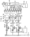
- FIG. 6 shows a modification of the working fluid control system 7 connected to the third pressure chambers A1, B1, C1 of the depressurizing devices A, B, C.
- Those parts shown in FIG. 6 which are identical to those parts shown in FIGS. 1 through 5 are denoted by identical reference numerals. However, the relief valves 45, 46 as safety valves are omitted from illustration.
- a pressure control valve 47a is connected between the working fluid tank 9 and a low-pressure side of the working fluid control system 7, i.e., a side of the working fluid control system 7 which is lower in pressure than the pressure control valve PV.
- the pressure control valve 47a is capable of maintaining a lower pressure in the working fluid control system 7.
- variable restrictors 44a, 44b, 44c are connected respectively to the third pressure chambers A1, B1, C1 in series with the shutoff valves 43a, 43b, 43c, respectively.
- the pipe 27 has a pressure-reducing valve 34 for imparting a slight pressure to the liquid material X in the fourth pressure chambers A2, B2, C2 to minimize any shock-induced movement of the pistons 23, 24 at the time the liquid material X is discharged from the fourth pressure chambers A2, B2, C2.
- the working fluid control system 7 shown in FIG. 6 has a first piping for supplying the working fluid from the third pressure chamber A1 (B1, C1) of the depressurizing device A (B, C) which carries out the suction mode for drawing the liquid material X, after the working fluid has been depressurized by the pressure control valve PV, to the third pressure chamber B1 (C1, A1) of the depressurizing device B (C, A) which carries out the discharge mode for discharging the liquid material X, a second piping for supplying the working fluid from the third pressure chamber C1 (A1, B1) of the depressurizing device C (A, B) which carries out the depressurization mode for depressurizing the liquid material X, after the working fluid has been depressurized by the restrictor 44c (44a, 44b), to the third pressure chamber B1 (C1, A1) of the depressurizing device B (C, A) which carries out the discharge mode for discharging the liquid material X, and a third piping for supplying
- the first piping specifically supplies the working fluid from the third pressure chamber A1 (B1, C1) of the depressurizing device A (B, C) which carries out the suction mode, after the working fluid has been depressurized by the shutoff valve 42a (42b, 42c) and the pressure control valve PV, to the third pressure chamber B1 (C1, A1) of the depressurizing device B (C, A) which carries out the discharge mode, through the shutoff valve 41b (41c, 41a).
- the second pipe specifically supplies the working fluid from the third pressure chamber C1 (A1, B1) of the depressurizing device C (A, B) which carries out the depressurization mode, after the working fluid has been depressurized by the restrictor 44c (44a, 44b) and the shutoff valve 43c (43a, 43b), to the third pressure chamber B1 (C1, A1) of the depressurizing device B (C, A) which carries out the discharge mode, through the shutoff valve 41b (41c, 41a).
- the third pipe specifically supplies the working fluid from the third pressure chamber A1 (B1, C1) of the depressurizing device A (B, C) which carries out the suction mode, without passage through the pressure control valve PV and the restrictor 44a (44b, 44c), directly to the third pressure chamber B1 (C1, A1) of the depressurizing device B (C, A) which has completed the discharge mode, through the shutoff valve 42b (42c, 42a).
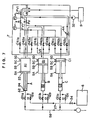
- FIG. 7 shows another modification of the working fluid control system 7 connected to the third pressure chambers A1, B1, C1 of the depressurizing devices A, B, C.
- Those parts shown in FIG. 7 which are identical to those parts shown in FIGS. 1 through 5 are denoted by identical reference numerals.
- the working fluid in the working fluid tank 9 can be supplied under a given pressure to the third pressure chambers A1, B1, C1 through a flow control valve FV1 and the shutoff valves 41a, 41b, 41c.
- the flow control valve FV1 supplies the working fluid through the shutoff valves 41a, 41b, 41c to the third pressure chambers A1, B1, C1 at a predetermined rate under a relatively low secondary pressure (downstream pressure) so that the liquid material X can be discharged from the fourth pressure chambers A2, B2, C2.
- a pressure control valve PV1 controls the working fluid supplied from the working fluid tank 9 by the pump 32 to flow through the flow control valve FV1 under a constant pressure, and returns the working fluid back to the working fluid tank 9 if the pressure of the working fluid exceeds a certain pressure level.
- the pressure control valve PV depressurizes the working fluid discharged from the third pressure chambers A1, B1, C1 through the shutoff valves 42a, 42b, 42c, and returns the depressurized working fluid through the pressure control valve PV1 back to the working fluid tank 9.
- the restrictor 44 gives a suitable resistance to the working fluid flowing out of the third pressure chambers A1, B1, C1.
- the working fluid that has passed through the restrictor 44 returns through the pressure control valve PV1 back to the working fluid tank 9.
- the intermediate-position limit switches SB serve to detect when the larger-diameter pistons 23 of the depressurizing devices A, B, C have reached the intermediate position in the larger-diameter cylinders 21.
- the intermediate-position limit switches SB are positioned such that the larger-diameter piston 23 of the depressurizing device A, for example, is detected by the corresponding intermediate-position limit switch SB when the larger-diameter piston 23 of the depressurizing device C is in the most retracted position, turning on the corresponding depressurization-position limit switch SD (or the pressure detector connected to the pipe connected to the larger-diameter cylinder 21), and also when the larger-diameter piston 23 of the depressurizing device B turns on the discharge-position limit switch SA.
- the pressure controller PC controls the pressure setting for the pressure control valve PV1 based on the detected pressure
- a flow controller FC controls the flow rate setting for the flow control valve FV1 based on the detected flow rate.
- the working fluid from the third pressure chamber A1 returns through the shutoff valve 42a, the pressure control valve PV, and the pressure control valve PV1 back to the working fluid tank 9 as indicated by the arrow VI in FIG. 7.
- the working fluid from the third pressure chamber C1 returns through the shutoff valve 43c, the restrictor 44, and the pressure control valve PV1 back to the working fluid tank 9 as indicated by the arrow VIII in FIG. 7.
- the shutoff valves 41a, 41b, 41c, 42b, 42c, 43a, 43b remain closed.
- the third pressure chamber B1 of the depressurizing device B which effects the discharge mode is supplied with the working fluid from the working fluid tank 9 through the flow control valve FV1 and the shutoff valve 41b when the pump 32 is actuated.
- the modified working fluid control system 7 shown in FIG. 7 differs from the working fluid control system 7 shown in FIG. 3 with respect to the stage of operation shown in FIG. 3 in that the third pressure chambers A1, B1, C1 and the fourth pressure chambers A2, B2, C2 of the depressurizing devices A, B, C are shifted from the modes shown in FIGS. 2 and 7 to the mode shown in FIG. 3. Specifically, when the completion of the discharge mode of the depressurizing device B is detected by the corresponding discharge-position limit switch SA, the shutoff valves 12b, 41b are closed, but the discharge mode of the depressurizing device C is not started. When the depressurization mode of the depressurizing device C is finished, the shutoff valve 43c is closed to keep the third pressure chamber C1 thereof as it is.
- the working fluid discharged from the third pressure chamber A1 returns through the shutoff valve 42a, the pressure control valve PV, and the pressure control valve PV1 back to the working fluid tank 9 as indicated by the arrow VI in FIG. 7.
- the third pressure chamber B1 of the depressurizing device B may be pressurized in preparation for the next mode of operation by opening the shutoff valve 42b to supply the working fluid as indicated by the arrow VII in FIG. 7 to the third pressure chamber B1 when the larger-diameter piston 23 of the depressurizing device B is detected by the discharge-position limit switch SA.
- the end of the pressurization mode may be detected by pressure detectors connected to the pipes connected to the larger-diameter cylinders 21 when the pressure detectors detect a predetermined pressure buildup therein.
- the discharge mode of the depressurizing device C is started when the larger-diameter piston 23 of the depressurizing device A has reached the predetermined intermediate position in the larger-diameter cylinder 21 as detected by the intermediate-position limit switch SB.
- the third pressure chambers A1, B1, C1 of the depressurizing devices A, B, C are in the same stage of operation as the third stage of operation shown in FIG. 4. Subsequently, the apparatus operates in the same stage of operation as the fourth stage of operation shown in FIG. 5.
- the working fluid flowing from the third pressure chamber B1 of the depressurizing device B through the shutoff valve 42b returns through the pressure control valve PV and the pressure control valve PV1 back to the working fluid tank 9.
- the discharge mode of the depressurizing device C is carried out when the shutoff valve 41c is opened and the working fluid in the working fluid tank 9 is supplied through the flow control valve FV1 and the shutoff valve 41c to the third pressure chamber C1 by the pump 32. In this manner, the total volume of the third pressure chambers A1, B1, C1 is maintained at a constant level in each suction mode.
- the shutoff valves 41b, 41c, 41a may be opened suitably to supply the working fluid tending to flow back to the working fluid tank 9 to the third pressure chambers B1, C1, A1 for effecting the discharge mode.
- the shutoff valves 41a, 41b, 41c may be opened suitably to supply part or all of the working fluid tending to flow back to the working fluid tank 9 to the third pressure chambers B1, C1, A1 for effecting the discharge mode. If at least part of the working fluid discharged in the suction mode or the depressurization mode is thus utilized for the discharge mode, then the burden on the pump 32 can be lessened as much as the amount of working fluid utilized for the discharge mode.
- the apparatus for processing a high-pressure liquid material according to the present invention and methods carried out by the apparatus offer the following advantages:
Landscapes
- Life Sciences & Earth Sciences (AREA)
- Engineering & Computer Science (AREA)
- Wood Science & Technology (AREA)
- Zoology (AREA)
- Chemical & Material Sciences (AREA)
- Food Science & Technology (AREA)
- Polymers & Plastics (AREA)
- Control Of Presses (AREA)
- Food Preservation Except Freezing, Refrigeration, And Drying (AREA)
- General Preparation And Processing Of Foods (AREA)
- Physical Or Chemical Processes And Apparatus (AREA)
Description
characterised in that:
Claims (14)
- An apparatus for processing a high-pressure liquid material (X),comprising:a high-pressure vessel (1);pressurizing means (2) for supplying a liquid material (X) to said high-pressure vessel in order to allow the high-pressure vessel to process the liquid material under a high pressure therein;depressurizing means (10) for receiving and depressurizing the processed liquid material supplied under a high pressure from said high-pressure vessel,
characterised in that:the apparatus further comprises a working fluid control system (7) for controlling said depressurizing means (10); in thatsaid depressurizing means has a plurality of cylinder devices (A,B,C) comprising respective pairs of interlinked pistons (23, 24) which define, in said cylinder devices, respective processing pressure chambers (A2,B2,C2) for selectively receiving the liquid material (X) from said high-pressure vessel (1), and respective working pressure chambers (A1,B1,C1) for selectively receiving a working fluid from said working fluid control system (7); in thatsaid working fluid control system (7) comprises means for bringing one of said working pressure chambers into communication with at least another one of the working pressure chambers to pass the working fluid therebetween for causing said cylinder devices to successively draw, depressurize, and discharge the liquid material in respective suction, depressurization, and discharge modes; in thatsaid working fluid control system (7) comprises means for supplying the working fluid discharged from the working pressure chamber (A1,B1,C1) of one of said cylinder devices (A,B,C) which is operating in at least the suction mode to the working pressure chamber of another one of said cylinder devices which is operating in the discharge mode; and in thatsaid working fluid control system (7) comprises means for supplying the working fluid discharged from the working pressure chamber (A1,B1,C1) of another one of said cylinder devices (A,B,C) which is operating in said depressurization mode, together with the working fluid discharged from the working pressure chamber of said one of the cylinder devices which is operating in said suction mode, to the working pressure chamber of said other one of said cylinder devices which is operating in said discharge mode. - An apparatus according to claim 1, wherein each of said cylinder devices (A,B,C) comprises a smaller-diameter cylinder (22) and a larger-diameter cylinder (21) disposed adjacent to said smaller-diameter cylinder, said pistons (23,24) being slidably fitted in said smaller-diameter cylinder and said larger-diameter cylinder, said piston (24) which defines one of the processing pressure chambers (A2,B2,C2) being smaller in diameter than said piston (23) which defines one of the working pressure chambers (A1,B1,C1).
- An apparatus according to claim 1 or 2, wherein said working fluid control system (7) comprises means for passing the working fluid discharged from the working pressure chamber (A1,B1,C1) of one of the cylinder devices (A,B,C) which is operating in said suction mode, through a pressure control valve (PV) to depressurize the working fluid, and then supplying the depressurized working fluid to the working pressure chamber (A1,B1,C1) of another of said cylinder devices (A,B,C) which is operating in the discharge mode.
- An apparatus according to any preceding claim, wherein said working fluid control system (7) comprises means for supplying the working fluid discharged from the working pressure chamber (A1,B1,C1) of one of said cylinder devices (A,B,C) which is operating in the suction mode to the working pressure chamber (A1,B1,C1) of another one of said cylinder devices (A,B,C) which has completed the discharge mode to apply a back pressure to said piston (24) which defines the processing pressure chamber (A2,B2,C2) of said other one of said cylinder devices (A,B,C).
- An apparatus according to claim 4, wherein said working fluid control system (7) comprises means for regulating said back pressure so as to substantially counterbalance the pressure of said liquid material (X) when the liquid is drawn from said high-pressure vessel (1) in the suction mode by said other one of the cylinder devices (A,B,C) which has completed the discharge mode.
- An apparatus according to any preceding claim, wherein said working fluid control system (7) comprises:a working fluid tank (9) containing the working fluid;a pump (30,31) for supplying the working fluid from said working fluid tank selectively to the working pressure chambers (A1,B1,C1) of said cylinder devices (A,B,C); andmeans for supplying the working fluid from said working fluid tank (9) to the working pressure chamber of one of said cylinder devices which is operating in the discharge mode.
- An apparatus according to claim 1, wherein said depressurizing means (10) has first, second, and third cylinder devices (A,B,C), and said working fluid control system (7) comprises:a first piping for depressurizing and supplying the working fluid from the working pressure chamber of the first cylinder device which is operating in the suction mode to the working pressure chamber of the second cylinder device which is operating in the discharge mode;a second piping for depressurising and supplying the working fluid from the working pressure chamber of the third cylinder device which is operating in the depressurization mode to the working pressure chamber of the second cylinder device which is operating in the discharge mode; anda third piping for supplying the working fluid from the working pressure chamber of the first cylinder device which is operating in the suction mode to the working pressure chamber of the second cylinder device which has completed the discharge mode.
- An apparatus according to claim 1, wherein said working fluid control system (7) comprises means for supplying the working fluid to the working pressure chamber (A1,B1,C1) of one of said cylinder devices (A,B,C) which has completed the discharge mode, and pressurizing the supplied working fluid to apply a back pressure to the piston (24) which defines the processing pressure chamber (A2,B2,C2) of said one of said cylinder devices.
- A method of processing a high-pressure liquid material (X), comprising the steps of:supplying a liquid material (X) to a high-pressure vessel (1) from pressurizing means (2);processing the liquid material under a high pressure in said high-pressure vessel;thereafter depressurizing the liquid material with depressurizing means (10); characterised in thatsaid depressurizing means has a plurality of cylinder devices (A,B,C) comprising respective pairs of interlinked pistons (23, 24) which define, in said cylinder devices, respective processing pressure chambers (A2,B2,C2) for selectively receiving the liquid material from said high-pressure vessel, and respective working pressure chambers (A1,B1,C1) for selectively receiving a working fluid; and in that the method further comprises the steps of:bringing one of said working pressure chambers into communication with at least another one of the working pressure chambers to pass the working fluid therebetween for causing said cylinder devices to successively draw, depressurize, and discharge the liquid material in respective suction, depressurization, and discharge modes;supplying the working fluid discharged from the working pressure chamber of one of said cylinder devices which is operating in at least the suction mode to the working pressure chamber of another one of said cylinder devices which is operating in the discharge mode; andsupplying the working fluid discharged from the working pressure chamber of another one of said cylinder devices which is operating in said depressurization mode, together with the working fluid discharged from the working pressure chamber of said one of the cylinder devices which is operating in said suction mode, to the working pressure chamber of said other one of said cylinder devices which is operating in said discharge mode.
- A method according to claim 9, wherein each of said cylinder devices (A,B,C) comprises a smaller-diameter cylinder (22) and a larger-diameter cylinder (21) disposed adjacent to said smaller-diameter cylinder, said pistons (23, 24) being slidably fitted in said smaller-diameter cylinder and said larger-diameter cylinder, said piston (23) which defines one of the processing pressure chambers (A2,B2,C2) being smaller in diameter than said piston (24) which defines one of the working pressure chambers (A1,B1,C1).
- A method according to claim 9 or 10, further comprising the step of:passing the working fluid discharged from the working pressure chamber (A1,B1,C1) of said one of the cylinder devices (A,B,C) which is operating in said suction mode, through a pressure control valve (PV) to depressurize the working fluid, and then supplying the depressurized working fluid to the working pressure chamber of said other one of said cylinder devices which is operating in the discharge mode.
- A method according to any of claims 9 to 11, further comprising the step of:supplying the working fluid discharged from the working pressure chamber (A1,B1,C1) of one of said cylinder devices (A,B,C) which is operating in the suction mode to the working pressure chamber of another one of said cylinder devices which has completed the discharge mode to apply a back pressure to said piston (24) which defines the processing pressure chamber (A2,B2,C2) of said other one of said cylinder devices.
- A method according to claim 12, further comprising the step of:regulating said back pressure so as to substantially counterbalance the pressure of said liquid material (X) when the liquid material is drawn from said high-pressure vessel (1) in the suction mode by said other one of the cylinder devices (A,B,C) which has completed the discharge mode.
- A method according to claim 9, further comprising the step of:supplying and pressurizing the working pressure chamber (A1,B1,C1) of one of said cylinder devices (A,B,C) which has completed the discharge mode with the working fluid from a dedicated pump (30,31) to apply a back pressure to said piston (24) which defines the processing pressure chamber (A2,B2,C2) of said one of said cylinder devices.
Applications Claiming Priority (2)
| Application Number | Priority Date | Filing Date | Title |
|---|---|---|---|
| JP302639/94 | 1994-11-14 | ||
| JP06302639A JP3073661B2 (en) | 1994-11-14 | 1994-11-14 | High-pressure liquid processing method and apparatus |
Publications (2)
| Publication Number | Publication Date |
|---|---|
| EP0713654A1 EP0713654A1 (en) | 1996-05-29 |
| EP0713654B1 true EP0713654B1 (en) | 1999-05-06 |
Family
ID=17911411
Family Applications (1)
| Application Number | Title | Priority Date | Filing Date |
|---|---|---|---|
| EP95308131A Expired - Lifetime EP0713654B1 (en) | 1994-11-14 | 1995-11-14 | Processing high-pressure liquid material |
Country Status (6)
| Country | Link |
|---|---|
| US (1) | US6136609A (en) |
| EP (1) | EP0713654B1 (en) |
| JP (1) | JP3073661B2 (en) |
| DE (1) | DE69509477T2 (en) |
| ES (1) | ES2132540T3 (en) |
| GR (1) | GR3030653T3 (en) |
Families Citing this family (15)
| Publication number | Priority date | Publication date | Assignee | Title |
|---|---|---|---|---|
| US5993172A (en) * | 1996-01-23 | 1999-11-30 | Flow International Corporation | Method and apparatus for pressure processing a pumpable substance |
| US5996478A (en) * | 1996-01-23 | 1999-12-07 | Flow International Corporation | Apparatus for pressure processing a pumpable food substance |
| US6158981A (en) * | 1998-06-18 | 2000-12-12 | Flow International Corporation | Method and apparatus for aseptic pressure-processing of pumpable substances |
| US6164930A (en) * | 1998-06-18 | 2000-12-26 | Flow International Corporation | Apparatus for regulating flow of a pumped substance |
| JP2002541876A (en) * | 1999-04-27 | 2002-12-10 | フロー インターナショナル コーポレイション | Method and apparatus for pressure treating a pumpable substance |
| DE60039336D1 (en) * | 2000-08-03 | 2008-08-14 | Koninkl Philips Electronics Nv | Fluid transport by pressure variation for the analysis of biological fluids |
| DE102004021035B3 (en) | 2004-04-07 | 2005-11-17 | Erbe Elektromedizin Gmbh | Apparatus for waterjet surgery |
| US7537019B2 (en) * | 2005-06-03 | 2009-05-26 | Avure Technologies Incorporated | Systems and methods to slowly reduce the pressure in a pressure chamber over time |
| NL1031852C2 (en) * | 2006-05-22 | 2007-11-23 | Maasland Nv | Agricultural machine. |
| DE102009042088A1 (en) * | 2009-09-18 | 2010-12-02 | Multivac Sepp Haggenmüller Gmbh & Co. Kg | Apparatus and method for high-pressure treatment of products |
| EP2595754B1 (en) | 2010-07-22 | 2018-04-04 | Gencell Biosystems Limited | Composite liquid cells |
| CA2888042A1 (en) | 2012-11-27 | 2014-06-05 | Gencell Biosystems Ltd. | Handling liquid samples |
| CN106029885A (en) | 2014-02-10 | 2016-10-12 | 基因细胞生物系统有限公司 | Composite liquid cell (clc) mediated nucleic acid library preparation device, and methods for using the same |
| ES2613878B1 (en) * | 2015-11-26 | 2018-02-15 | Metronics Technologies, S.L. | SYSTEM AND METHOD FOR HIGH PRESSURE FOOD LIQUID TREATMENT |
| JP7048498B2 (en) * | 2016-01-15 | 2022-04-05 | ザ コカ・コーラ カンパニー | Continuous high pressure treatment of food and beverage products |
Family Cites Families (10)
| Publication number | Priority date | Publication date | Assignee | Title |
|---|---|---|---|---|
| JPS5852689B2 (en) * | 1979-10-18 | 1983-11-24 | 工業技術院長 | Method and apparatus for supplying and depressurizing high-pressure fluids |
| US4512188A (en) * | 1982-08-25 | 1985-04-23 | Getty Oil Company | Flow rate control and metering means for shear-sensitive liquids |
| JPH04241869A (en) * | 1991-01-09 | 1992-08-28 | Mitsubishi Heavy Ind Ltd | Continuous treating device for high-pressure liquid |
| JP2622315B2 (en) * | 1991-04-17 | 1997-06-18 | 三菱重工業株式会社 | Continuous press |
| JPH05317015A (en) * | 1992-05-22 | 1993-12-03 | Mitsubishi Heavy Ind Ltd | Continuous treating apparatus for high-pressure liquid |
| JP3154454B2 (en) * | 1993-02-08 | 2001-04-09 | 日本電信電話株式会社 | Coding of interlaced image signals |
| JPH06277267A (en) * | 1993-03-25 | 1994-10-04 | Mitsubishi Heavy Ind Ltd | High pressure liquid continuous processor |
| JPH06277266A (en) * | 1993-03-25 | 1994-10-04 | Mitsubishi Heavy Ind Ltd | High pressure liquid continuous processor |
| JP3021231B2 (en) * | 1993-05-25 | 2000-03-15 | 三菱重工業株式会社 | High pressure liquid continuous treatment method |
| JP3285662B2 (en) * | 1993-06-08 | 2002-05-27 | 三菱重工業株式会社 | High pressure liquid continuous processing method |
-
1994
- 1994-11-14 JP JP06302639A patent/JP3073661B2/en not_active Expired - Fee Related
-
1995
- 1995-08-21 US US08/517,387 patent/US6136609A/en not_active Expired - Lifetime
- 1995-11-14 DE DE69509477T patent/DE69509477T2/en not_active Expired - Lifetime
- 1995-11-14 EP EP95308131A patent/EP0713654B1/en not_active Expired - Lifetime
- 1995-11-14 ES ES95308131T patent/ES2132540T3/en not_active Expired - Lifetime
-
1999
- 1999-06-30 GR GR990401739T patent/GR3030653T3/en unknown
Also Published As
| Publication number | Publication date |
|---|---|
| JP3073661B2 (en) | 2000-08-07 |
| GR3030653T3 (en) | 1999-10-29 |
| US6136609A (en) | 2000-10-24 |
| JPH08131135A (en) | 1996-05-28 |
| ES2132540T3 (en) | 1999-08-16 |
| DE69509477D1 (en) | 1999-06-10 |
| EP0713654A1 (en) | 1996-05-29 |
| DE69509477T2 (en) | 1999-11-25 |
Similar Documents
| Publication | Publication Date | Title |
|---|---|---|
| US6136609A (en) | Method of and apparatus for processing high-pressure liquid material | |
| EP3565655B1 (en) | System and method for the treatment of water by reverse osmosis or nanofiltration | |
| CA2609699C (en) | Systems and methods to reduce the pressure in a pressure chamber | |
| EP3104158B1 (en) | Hydraulic testing method and device | |
| EP1115465A1 (en) | System for simultaneously pumping solvent for a plurality of chromatography columns | |
| US5165325A (en) | Continuous pressurizing apparatus for liquid | |
| US5788934A (en) | Process and machine for high-pressure sterilization of products | |
| GB2403762A (en) | Hydraulic shield support | |
| EP4335613A1 (en) | Device and method for reforming plastic preforms into plastic containers with controlled compressed air recycling | |
| HK1046511A1 (en) | Method and device for desalting water | |
| EP2076707B1 (en) | Apparatus for the rapid filling of compressed gas containers | |
| DE2128261A1 (en) | Device for generating a constant mass flow of a medium under high pressure | |
| KR20140084154A (en) | Preparative column chromatography system | |
| CN102286832B (en) | Air pressure regulating system of jet loom and method thereof | |
| EP0793023B1 (en) | Hydraulic system | |
| JP2668744B2 (en) | Pressure oil supply device | |
| EP4335614A1 (en) | Device and method for reforming plastic preforms into plastic containers with controlled compressed air recycling | |
| US2883859A (en) | Operating mechanism for a pipe testing machine | |
| US5454669A (en) | Yield valve | |
| CN222209959U (en) | Air supply system for assembly test | |
| RU2287097C1 (en) | Fluid-pressure system for cyclic loading of bench for testing high-pressure hoses | |
| JPS636436A (en) | Repetitive pressurizing test device | |
| JPH08206890A (en) | Pressure reducing method and device for cold isostatic pressurization device | |
| SU1643970A1 (en) | Method for testing leak-proofness of pieces | |
| JPH09314391A (en) | Method for reducing pressure of cold isotropic pressurizing device and device therefor |
Legal Events
| Date | Code | Title | Description |
|---|---|---|---|
| PUAI | Public reference made under article 153(3) epc to a published international application that has entered the european phase |
Free format text: ORIGINAL CODE: 0009012 |
|
| AK | Designated contracting states |
Kind code of ref document: A1 Designated state(s): BE DE ES FR GB GR IT LU NL PT |
|
| 17P | Request for examination filed |
Effective date: 19960801 |
|
| 17Q | First examination report despatched |
Effective date: 19970114 |
|
| GRAG | Despatch of communication of intention to grant |
Free format text: ORIGINAL CODE: EPIDOS AGRA |
|
| GRAG | Despatch of communication of intention to grant |
Free format text: ORIGINAL CODE: EPIDOS AGRA |
|
| GRAH | Despatch of communication of intention to grant a patent |
Free format text: ORIGINAL CODE: EPIDOS IGRA |
|
| GRAH | Despatch of communication of intention to grant a patent |
Free format text: ORIGINAL CODE: EPIDOS IGRA |
|
| GRAA | (expected) grant |
Free format text: ORIGINAL CODE: 0009210 |
|
| AK | Designated contracting states |
Kind code of ref document: B1 Designated state(s): BE DE ES FR GB GR IT LU NL PT |
|
| REF | Corresponds to: |
Ref document number: 69509477 Country of ref document: DE Date of ref document: 19990610 |
|
| ET | Fr: translation filed | ||
| REG | Reference to a national code |
Ref country code: ES Ref legal event code: FG2A Ref document number: 2132540 Country of ref document: ES Kind code of ref document: T3 |
|
| REG | Reference to a national code |
Ref country code: PT Ref legal event code: SC4A Free format text: AVAILABILITY OF NATIONAL TRANSLATION Effective date: 19990507 |
|
| PLBE | No opposition filed within time limit |
Free format text: ORIGINAL CODE: 0009261 |
|
| STAA | Information on the status of an ep patent application or granted ep patent |
Free format text: STATUS: NO OPPOSITION FILED WITHIN TIME LIMIT |
|
| 26N | No opposition filed | ||
| REG | Reference to a national code |
Ref country code: GB Ref legal event code: IF02 |
|
| PGFP | Annual fee paid to national office [announced via postgrant information from national office to epo] |
Ref country code: DE Payment date: 20101119 Year of fee payment: 16 |
|
| PGFP | Annual fee paid to national office [announced via postgrant information from national office to epo] |
Ref country code: IT Payment date: 20101126 Year of fee payment: 16 Ref country code: GR Payment date: 20101119 Year of fee payment: 16 Ref country code: GB Payment date: 20101118 Year of fee payment: 16 |
|
| PGFP | Annual fee paid to national office [announced via postgrant information from national office to epo] |
Ref country code: PT Payment date: 20111114 Year of fee payment: 17 Ref country code: NL Payment date: 20111124 Year of fee payment: 17 Ref country code: ES Payment date: 20111125 Year of fee payment: 17 Ref country code: FR Payment date: 20111130 Year of fee payment: 17 Ref country code: LU Payment date: 20111130 Year of fee payment: 17 |
|
| PGFP | Annual fee paid to national office [announced via postgrant information from national office to epo] |
Ref country code: BE Payment date: 20111110 Year of fee payment: 17 |
|
| REG | Reference to a national code |
Ref country code: PT Ref legal event code: MM4A Free format text: LAPSE DUE TO NON-PAYMENT OF FEES Effective date: 20130514 |
|
| BERE | Be: lapsed |
Owner name: *KAGOME K.K. Effective date: 20121130 |
|
| REG | Reference to a national code |
Ref country code: NL Ref legal event code: V1 Effective date: 20130601 |
|
| GBPC | Gb: european patent ceased through non-payment of renewal fee |
Effective date: 20121114 |
|
| REG | Reference to a national code |
Ref country code: FR Ref legal event code: ST Effective date: 20130731 |
|
| PG25 | Lapsed in a contracting state [announced via postgrant information from national office to epo] |
Ref country code: GR Free format text: LAPSE BECAUSE OF NON-PAYMENT OF DUE FEES Effective date: 20130604 Ref country code: IT Free format text: LAPSE BECAUSE OF NON-PAYMENT OF DUE FEES Effective date: 20121114 Ref country code: PT Free format text: LAPSE BECAUSE OF NON-PAYMENT OF DUE FEES Effective date: 20130514 Ref country code: BE Free format text: LAPSE BECAUSE OF NON-PAYMENT OF DUE FEES Effective date: 20121130 Ref country code: NL Free format text: LAPSE BECAUSE OF NON-PAYMENT OF DUE FEES Effective date: 20130601 |
|
| REG | Reference to a national code |
Ref country code: GR Ref legal event code: ML Ref document number: 990401739 Country of ref document: GR Effective date: 20130604 |
|
| REG | Reference to a national code |
Ref country code: DE Ref legal event code: R119 Ref document number: 69509477 Country of ref document: DE Effective date: 20130601 |
|
| PG25 | Lapsed in a contracting state [announced via postgrant information from national office to epo] |
Ref country code: DE Free format text: LAPSE BECAUSE OF NON-PAYMENT OF DUE FEES Effective date: 20130601 |
|
| PG25 | Lapsed in a contracting state [announced via postgrant information from national office to epo] |
Ref country code: FR Free format text: LAPSE BECAUSE OF NON-PAYMENT OF DUE FEES Effective date: 20121130 Ref country code: GB Free format text: LAPSE BECAUSE OF NON-PAYMENT OF DUE FEES Effective date: 20121114 |
|
| REG | Reference to a national code |
Ref country code: ES Ref legal event code: FD2A Effective date: 20140305 |
|
| PG25 | Lapsed in a contracting state [announced via postgrant information from national office to epo] |
Ref country code: LU Free format text: LAPSE BECAUSE OF NON-PAYMENT OF DUE FEES Effective date: 20121114 Ref country code: ES Free format text: LAPSE BECAUSE OF NON-PAYMENT OF DUE FEES Effective date: 20121115 |