EP0713219B1 - Tape drive with floating support for insert - Google Patents
Tape drive with floating support for insert Download PDFInfo
- Publication number
- EP0713219B1 EP0713219B1 EP95117971A EP95117971A EP0713219B1 EP 0713219 B1 EP0713219 B1 EP 0713219B1 EP 95117971 A EP95117971 A EP 95117971A EP 95117971 A EP95117971 A EP 95117971A EP 0713219 B1 EP0713219 B1 EP 0713219B1
- Authority
- EP
- European Patent Office
- Prior art keywords
- wall
- data storage
- suspension
- storage drive
- frame
- Prior art date
- Legal status (The legal status is an assumption and is not a legal conclusion. Google has not performed a legal analysis and makes no representation as to the accuracy of the status listed.)
- Expired - Lifetime
Links
- 239000000725 suspension Substances 0.000 claims description 66
- 238000013500 data storage Methods 0.000 claims description 39
- 239000000463 material Substances 0.000 claims description 3
- 230000005291 magnetic effect Effects 0.000 description 13
- 230000003287 optical effect Effects 0.000 description 6
- 230000002093 peripheral effect Effects 0.000 description 3
- 230000002411 adverse Effects 0.000 description 2
- 125000006850 spacer group Chemical group 0.000 description 2
- 230000001627 detrimental effect Effects 0.000 description 1
- 230000009977 dual effect Effects 0.000 description 1
- 230000000694 effects Effects 0.000 description 1
- 239000003302 ferromagnetic material Substances 0.000 description 1
- 230000017525 heat dissipation Effects 0.000 description 1
- 238000002347 injection Methods 0.000 description 1
- 239000007924 injection Substances 0.000 description 1
- 238000009434 installation Methods 0.000 description 1
- 238000004519 manufacturing process Methods 0.000 description 1
- 239000002184 metal Substances 0.000 description 1
- 239000002991 molded plastic Substances 0.000 description 1
Images




Classifications
-
- G—PHYSICS
- G11—INFORMATION STORAGE
- G11B—INFORMATION STORAGE BASED ON RELATIVE MOVEMENT BETWEEN RECORD CARRIER AND TRANSDUCER
- G11B33/00—Constructional parts, details or accessories not provided for in the other groups of this subclass
-
- G—PHYSICS
- G11—INFORMATION STORAGE
- G11B—INFORMATION STORAGE BASED ON RELATIVE MOVEMENT BETWEEN RECORD CARRIER AND TRANSDUCER
- G11B33/00—Constructional parts, details or accessories not provided for in the other groups of this subclass
- G11B33/02—Cabinets; Cases; Stands; Disposition of apparatus therein or thereon
- G11B33/08—Insulation or absorption of undesired vibrations or sounds
Definitions
- the present invention relates to data storage and data retrieval for computers, particularly to a suspension member for holding the chassis of a data storage drive such as a tape drive.
- Figure 1 is a partial perspective view of a computer housing 12 showing a data storage drive, such as a tape drive 14 held within a tubular suspension 16, the tubular suspension mounted to parallel side walls 18 (only one shown) of the computer housing.
- a data cartridge (not shown) is insertable into the tape drive 14 through a door 15 of the housing 12.
- Figure 3 illustrates the typical suspension of a head within the tape drive 14 including the head support 66, and a bottom support 67 holding a magnetic head 68 on a pivotably tray 69.
- the head support 66 is fixed at region 66a to lattice structure 66b of the tape drive 14.
- the head tray 69 is journal on an axle 69a fixed at points C and D to the head support 66 and bottom support 67 respectively.
- the head support 66 protrudes upwardly through the aperture 64 of the printed circuit board 38.
- Figure 5 illustrates the bottom wall 30 of the suspension 16 including a joint 70 having spot welds or rivets 72.
- the suspension 16 can thus be fold formed of stamped sheet metal and seamed to form the rectangular cylinder.
- Stamped formed on the bottom wall 30 are three leaf springs 74a, 74b, 74c directed inwardly with inwardly formed raised semispheres or buttons 76a, 76b, 76c.
- the buttons 76a, 76b, 76c substantially underlie the protrusions 60a, 60b, 60c such that the tape drive 14 can be resiliently clasped therebetween, in a three point loading-planar orientation.
- Also arranged on the bottom wall 30 are threaded apertures 80a, 80b, 80c, 80d for screw mounting of the suspension 16 to the computer housing as applicable.
- Figure 6 illustrates the right side of the suspension 16 including the rectangular aperture 58 which is stamped formed along with a circular raised boss 84 which assists in stiffening and properly orienting the rectangular aperture 58.
- the aperture 58 is sufficiently larger than the tabs 56 to allow for mistolerances without binding.
Landscapes
- Supporting Of Heads In Record-Carrier Devices (AREA)
- Casings For Electric Apparatus (AREA)
Description
- The present invention relates to data storage and data retrieval for computers, particularly to a suspension member for holding the chassis of a data storage drive such as a tape drive.
- Computers, particularly personal computers, can use a plurality of data storage devices or drives depending on application. Typically, a magnetic tape drive, a magnetic floppy disk drive, and/or magnetic hard disk drive, are used in personal computers for storing data and programs and retrieval therefrom. Additionally, an optical disk drive can be used such as a CD-ROM.
- In all kinds of magnetic or optical storage, it is important that the magnetic or optical head is properly aligned relative to the preset spacial datums for the storage media, e.g., the spacial position of the data cartridge within the drive. After adjustment of the magnetic or optical head relative to the storage datum, this adjustment must remain stable even after the physical mounting of the data storage drive into a computer housing. Typically, the mounting surfaces in computer housings are imprecisely positioned, having wide dimensional tolerances. When tightening the mounting screws for holding the chassis of a data storage drive, there can be a distortion of the data storage drive chassis by forced conformance to the mounting surfaces and thereby a change of the alignment of the magnetic or optical head relative to the preset spacial datums for storage media within the drive.
- The document US-A-4 979 909 discloses a suspension for mounting a data storage drive into a computer housing, comprising a rectangular cylinder for receiving said data storage drive therein having means for mounting said cylinder to said computer housing and springs provided in the front part of sliding members for said data storage drive for resiliently supporting said drive within said cylinder. Further, the suspension comprises a means for locking said data storage drive into said cylinder when fully inserted, comprising a aperture through a side wall of said cylinder for receiving a resilient tab connected to the data storage drive.
- The document US-A-5 123 721 discloses a device for securing a peripheral equipment of computer, where no fastening tools are required, wherein peripheral equipment is introduced in a guide slot formed within the computer body, and wherein flexible members are installed on the opposite sides of the peripheral equipment. One end of the flexible member is elastically supported against the sides of the guide slot, and the other end is coupled with the front plate of the computer body. The embodiment shown on Fig. 5 of US-A-5 123 721 has been used to delimit the two-part form of claim 1.
- IBM Technical Disclosure Bulletin, Vol. 32, No. 10A, March 1990, pages 199 to 201, discloses a disk-access storage drive retaining device comprises to tension springs which act as shock-absorbing springs as they apply pressure to the drive rails compensating for the built-in assembly clearance.
- It is an object of the present invention to provide a suspension arrangement for the chassis of a data storage drive which accommodates distortion caused by securement to a computer housing. It is an object of the present invention to provide a suspension which also provides a electromagnetic shielding surrounding the data storage drive. It is an object of the present invention to provide a floating suspension for a data storage drive which can be secured within a computer housing either before or after the data storage drive is secured to the suspension. It is an object of the present invention to provide a suspension for a data storage drive which resiliently mounts a data storage drive allowing for distortion or mistolerance of the suspension due to manufacturing tolerances of the suspension, or of the computer housing to which it is attached.
- The invention is a suspension for mounting a data storage drive as claimed in claim 1.
- The objects of the invention are achieved in that a rectangular tubular suspension is provided having resilient members for holding a data storage drive within the tubular suspension in a non-fixed or "floating" manner. The objects are achieved in that the tubular suspension is constructed of a material which provides an electromagnetic shielding of the data storage drive. The objects are achieved in that the tubular suspension provides mounting holes for securement to rails or walls within the computer housing. The suspension receives the data storage drive through one of its open ends and the data storage drive is secured in place, for example, by spring tabs received in apertures in the tubular suspension.
- The objects are achieved in that a three-point suspension holds the data storage drive and defines an appropriate datum plane such as a horizontal plane, and relieves distortion forces on the chassis caused by its fixation into a computer housing. The suspension provides three leaf springs on a bottom wall in corresponding planar relationship with three protrusions on an opposite top wall thereof. The objects of the invention are achieved in that a leaf spring is arranged on one side wall and protrusions are arranged on the respective opposite side wall wherein the data storage drive chassis is clamped between the opposing leaf spring and protrusions, thus forming a three point loading to orient the drive in the datum plane.
- The invention is particularly advantageous for a tape drive wherein the magnetic head of the tape drive is oriented by top and bottom walls of the data storage drive chassis. Any distortion of the chassis caused by forced mounting to a computer housing having dimensional mistolerances would tend to disorient the otherwise preset position of the head with respect to a tape cartridge carried within the data storage drive. Therefore, the tubular suspension receives the tape drive chassis through a back open end thereof, the tubular suspension having screw holes for lateral mounting of the suspension within the computer housing. The bottom leaf springs opposing top protrusions, and a side leaf spring facing opposite side dual protrusions, positions the tape drive in a proper plane, and into proper position within that plane, in a resilient or "floating" fashion. Therefore, the tubular suspension can be secured in place by screws or otherwise in a fixed fashion and any distortion will be compensated for by the resilient nature of the leaf springs and protrusions. The relative position of the head vis-a-vis the chassis remains substantially constant.
-
- Figure 1 is a perspective view of a computer housing with a cover portion removed for clarity, including a suspension of the present invention holding a data storage drive;
- Figure 2 is an exploded rear perspective view of the tape drive and suspension member shown in Figure 1;
- Figure 3 is a partial sectional view taken generally along line III-III of Figure 4;
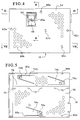
- Figure 4 is a top plan view of the assembly shown in Figure 2 in an assembled state;
- Figure 5 is a bottom view of the assembly shown in Figure 4;
- Figure 6 is a right side view of the suspension shown in Figure 2;
- Figure 7 is a left side view of the suspension shown in Figure 2;
- Figure 8 is a sectional view taken generally along line VIII-VIII of Figure 4;
- Figure 9 is a sectional view taken generally along line IX-IX of Figure 4;
- Figure 10 is a sectional view taken generally along line X-X of Figure 7; and
- Figure 11 is a sectional view taken generally along line XI-XI of Figure 7.
-
- Figure 1 is a partial perspective view of a
computer housing 12 showing a data storage drive, such as atape drive 14 held within atubular suspension 16, the tubular suspension mounted to parallel side walls 18 (only one shown) of the computer housing. A data cartridge (not shown) is insertable into thetape drive 14 through a door 15 of thehousing 12. - Figure 2 shows the
tape drive 14 separated from thesuspension 16. Thetape drive 14 is inserted through a backopen end 20 of thesuspension 16 in a direction A. Thesuspension 16 is a rectangular tubularmember having perforations 22 through atop wall 24 substantially over its entire surface (only a small number are shown). Theseperforations 22 are for heat dissipation purposes.Perforations 22 are also provided throughright side wall 26 andleft side wall 28 as well as throughout abottom wall 30. Thesuspension 16 can be optimally fashioned of a electromagnetic shielding material. - The tape drive has a front opening 34 for receiving a tape cartridge therein, the opening in registry with the door 15 of the
housing 12. Thefront opening 34 is defined by a top mounted printedcircuit board 38,right side wall 40,left side wall 42 and acartridge supporting surface 44. A bottom mounted printedcircuit board 46 delimits a bottom extent of the tape drive. Theright side wall 40 and theleft side wall 42 are connected by aback wall 50. Between theleft side wall 42 and theright side wall 40, theback wall 50 and the front opening 34 and between thetop circuit board 38 and thebottom circuit board 46 is a lattice type framework molded integrally with theside walls back wall 50, andcassette supporting surface 44, forming a chassis. The chassis can be an injection molded plastic. The lattice type framework includes structure for supporting the magnetic head in fixed orientation as described in Figure 3. - The
right side wall 40 and theleft side wall 42 each comprise aresilient locking tab 56 which engages into arectangular aperture 58 of thesuspension 16 when thetape drive 14 is fully inserted within thesuspension 16. Thesuspension 16 is preferably constructed of a ferromagnetic material to act as a magnetic shield to prevent interference with the magnetic head. Thetop wall 24 provides inwardly stamped major protrusions orindents indents major protrusions major protrusions top wall 24 provides arectangular aperture 64 for receiving ahead support 66 on thetape drive 14. - The printed
circuit boards tape drive 14 such that the tape drive can be a modular and complete unit for sale and installation into a computer housing. - Figure 3 illustrates the typical suspension of a head within the
tape drive 14 including thehead support 66, and abottom support 67 holding amagnetic head 68 on apivotably tray 69. Thehead support 66 is fixed atregion 66a tolattice structure 66b of thetape drive 14. Thehead tray 69 is journal on anaxle 69a fixed at points C and D to thehead support 66 andbottom support 67 respectively. Thehead support 66 protrudes upwardly through theaperture 64 of the printedcircuit board 38. Thus, any distortion of thetape drive 14, particularly the chassis causes a change in the positions of points C and D and will change the orientation of theaxle 69a and thus thehead 68. Even small misorientations can adversely effect performance of thehead 68. - Figure 4 illustrates the assembly of Figure 2 in an assembled condition wherein the
head support 66 is registered within theaperture 64. Themajor protrusions 60a,b,c are arranged in a triangle pattern and theminor protrusions 62a,b,c are generally arranged along an axial center line. - Figure 5 illustrates the
bottom wall 30 of thesuspension 16 including a joint 70 having spot welds or rivets 72. Thesuspension 16 can thus be fold formed of stamped sheet metal and seamed to form the rectangular cylinder. Stamped formed on thebottom wall 30 are threeleaf springs buttons buttons protrusions tape drive 14 can be resiliently clasped therebetween, in a three point loading-planar orientation. Also arranged on thebottom wall 30 are threadedapertures suspension 16 to the computer housing as applicable. - Figure 6 illustrates the right side of the
suspension 16 including therectangular aperture 58 which is stamped formed along with a circular raisedboss 84 which assists in stiffening and properly orienting therectangular aperture 58. Theaperture 58 is sufficiently larger than thetabs 56 to allow for mistolerances without binding. - Figure 7 illustrates the left side view which includes a
leaf spring 74d including an inwardly directedbutton 76d at approximately a center position of theleft side 28. Theleaf spring 74d is cut and bent inwardly from theleft side wall 28. Thus, when thetape drive 14 is inserted into thesuspension 16, the tape drive is resiliently held between theprotrusions button portion 76d of theleaf spring 74d, in a three point horizontal positioning. The right side wall provides threadedapertures apertures suspension 16 to thewalls 18 within the computer housing as applicable. - Figure 8 illustrates the loading between the
protrusions buttons circuit boards side wall 40 and the lattice framework of the tape drive (not shown). Theleaf springs bottom wall 30. - Figures 9-11 illustrate in sectional views the engagement between the
tape drive 14 and thesuspension 16. As illustrated, thetape drive 14 is held elevated from the bottom 30 of thesuspension 16. Also, thetape drive 14 is held at a distance below thetop wall 30 of thesuspension 16. Thus, thetape drive 14 "floats" within thesuspension 16 held by the three point loading of theleaf springs protrusions leaf spring 74d and theprotrusions - The
shallow protrusions top wall 30 toward the printedcircuit board 38 serve a different function than suspension of thetape drive 14. It is possible that in constructing thesuspension 16, or the printedcircuit board 38, thetop wall 30 and theboard 38 could be bowed toward each other in a central region laterally between theprotrusions shallow protrusions circuit board 38 and thetop wall 30. Theseshallow protrusions circuit board 38 at any undesirable electrical location and act as spacers to maintain the distance B between thetop wall 30 and the printedcircuit board 38. - It can be understood that because the
tape drive 14 is held within thesuspension 16 by resilient leaf springs rather than a fixed connection such as a screwed connection, any distortion applied to thesuspension 16 will be compensated for by the resilient nature of the leaf springs so as not to transmit this distortion to the tape drive itself. This is important where the tape drive head has been preset in orientation with regard to the tape cartridge datum of the tape drive and any distortion relative between the two parts is detrimental. - Although a tape drive is illustrated and described above as an exemplary embodiment of the invention, any type of data storage drive, where precise location of a magnetic or optical head to its associated data storage medium is desirably maintained, could advantageously utilize the suspension of the present invention and such devices are encompassed by the present invention.
Claims (11)
- A suspension for mounting a data storage drive into a computer housing, comprising :characterised by :a suspension frame having at least a first wall (24) and a second wall (30) defining a space therebetween;a first resilient member (e.g. 74a) mounted to said second wall (30);a first protrusion (e.g. 60a) extending inwardly from said first wall (24), said first resilient member (74a) pressing said data storage drive (14) against said first protrusion (60a) when said data storage drive (14) is received within said space.
- The suspension according to claim 1 wherein said frame comprises opposite side walls (26, 28) connected respectively to said first wall (24) and said second wall (30), said frame closely surrounding said data storage drive (14) when installed into said space.
- The suspension according to claim 2 further comprising a further resilient member (74d) mounted on one (28) of said side walls and two spaced apart inwardly directed further protrusions (60d, 60e) mounted on an opposite one (26) of said side walls.
- The suspension according to claim 1 further comprising second and third resilient members (74b, 74c) and second and third protrusions (60b, 60c), said first, second and third resilient members (74a, 74b, 74c) and said first, second and third protrusions (60a, 60b, 60c) acting in respective resilient protrusion member pairs to provide a three-point planar suspension of said data storage drive (14) in said frame.
- The suspension according to claim 4 wherein said resilient members comprise leaf springs (74a, 74b, 74c) formed into said second wall (30) and said protrusions comprise indents (60a, 60b, 60c) formed into said first wall (24).
- The suspension according to claim 1 wherein said frame is a metallic rectangular cylinder having heat dissipating holes (22).
- The suspension according to claim 1 wherein said data storage drive comprises a tape drive unit (14) having a first printed circuit board (38) connected on a first side thereof and a second printed circuit board (46) connected on a second side thereof and said first resilient members and said protrusions abut said first and second printed circuit boards (38, 46), respectively.
- The suspension according to claim 7 further comprising secondary protrusions (62a, 62b, 62c) on at least one (30) of said first wall (24) and said second wall (30) in a central region thereof for spacing said at least one (30) of said first wall (24) and said second wall (30) from one of said first (38) and second (46) printed circuit boards respectively.
- The suspension according to claim 1 wherein said frame comprises opposite side walls (26, 28) connected respectively to said first wall (24) and said second wall (30) said frame closely surrounding said data storage drive (14) when installed into said space and comprising an aperture (58) on at least one of said side walls for receiving a resilient tab (56) of said data storage drive (14) to lock said data storage drive into said frame.
- The suspension according to claim 1 wherein said frame comprises threaded holes (80a, 80b, 80c, 80d) for securing said frame to said computer housing (12).
- The suspension according to claim 1 wherein said frame is composed of an electromagnetic shielding material.
Applications Claiming Priority (2)
| Application Number | Priority Date | Filing Date | Title |
|---|---|---|---|
| US339835 | 1994-11-15 | ||
| US08/339,835 US5548480A (en) | 1994-11-15 | 1994-11-15 | Tape drive with floating support for insert |
Publications (3)
| Publication Number | Publication Date |
|---|---|
| EP0713219A2 EP0713219A2 (en) | 1996-05-22 |
| EP0713219A3 EP0713219A3 (en) | 1997-01-29 |
| EP0713219B1 true EP0713219B1 (en) | 1999-10-20 |
Family
ID=23330819
Family Applications (1)
| Application Number | Title | Priority Date | Filing Date |
|---|---|---|---|
| EP95117971A Expired - Lifetime EP0713219B1 (en) | 1994-11-15 | 1995-11-15 | Tape drive with floating support for insert |
Country Status (4)
| Country | Link |
|---|---|
| US (1) | US5548480A (en) |
| EP (1) | EP0713219B1 (en) |
| JP (1) | JPH08212767A (en) |
| DE (1) | DE69512864T2 (en) |
Families Citing this family (25)
| Publication number | Priority date | Publication date | Assignee | Title |
|---|---|---|---|---|
| JPH08255471A (en) * | 1995-03-16 | 1996-10-01 | Fujitsu Ltd | Storage unit |
| EP0763792A1 (en) * | 1995-09-13 | 1997-03-19 | Hewlett-Packard Company | Fixing piece for data storage drive and other units |
| US5673171A (en) * | 1995-12-05 | 1997-09-30 | Compaq Computer Corporation | Hard disc drive support tray apparatus with built-in handling shock reduction, EMI shielding and mounting alignment structures |
| US5682291A (en) * | 1996-07-10 | 1997-10-28 | Dell U.S.A., L.P. | Carrier for a computer device |
| US5654875A (en) * | 1996-07-26 | 1997-08-05 | Ibm | Isolator mounting system for small form factor hard disk drive |
| KR100190529B1 (en) * | 1996-08-12 | 1999-06-01 | 윤종용 | Computer system with built-in VTR |
| US5917676A (en) * | 1997-04-30 | 1999-06-29 | Seagate Technology, Inc. | Disc drive vibration reduction device |
| US6021041A (en) * | 1997-06-09 | 2000-02-01 | Dell U.S.A., L.P | Tuned shock absorbing system for portable computer hard disc drives |
| US5995365A (en) * | 1997-08-04 | 1999-11-30 | Dell U.S.A. L.P. | Computer with hard disk drive carrier |
| US6209842B1 (en) | 1998-05-27 | 2001-04-03 | International Business Machines Corporation | Laminated damping device for a carrier |
| US6247944B1 (en) | 1998-06-15 | 2001-06-19 | Compaq Computer Corporation | Slide-activated, spring-loaded ejector for hot-pluggable disk drive carrier |
| US6442021B1 (en) | 1998-06-15 | 2002-08-27 | Compaq Computer Corporation | Hot-pluggable disk carrier having enhanced rotational drive vibration control capability |
| US6373696B1 (en) | 1998-06-15 | 2002-04-16 | Compaq Computer Corporation | Hard drive cooling using finned heat sink and thermally conductive interface pad |
| US6084768A (en) * | 1998-06-15 | 2000-07-04 | Compaq Computer Corporation | Non-operational shock protection for disk carriers in a high density package |
| US6088221A (en) * | 1998-06-15 | 2000-07-11 | Compaq Computer Corporation | Hot-pluggable disk drive carrier assembly with no loose parts |
| US6216999B1 (en) * | 1998-11-05 | 2001-04-17 | Apple Computer, Inc. | Floating mount and method for mounting a device to a chassis thereby |
| US6366457B1 (en) | 2000-08-30 | 2002-04-02 | International Business Machines Corporation | Bracket for mounting a computer drive device |
| GB2371413A (en) | 2001-01-17 | 2002-07-24 | Sun Microsystems Inc | Removable media drives |
| US6556433B1 (en) * | 2001-04-17 | 2003-04-29 | Gateway, Inc. | Friction fastener and method for computer components |
| KR100443059B1 (en) * | 2001-11-13 | 2004-08-04 | 이종규 | Industrial computer casing |
| US6698060B1 (en) * | 2002-06-10 | 2004-03-02 | Hando Industrial Co., Ltd. | Caster structure |
| US6661677B1 (en) | 2002-08-12 | 2003-12-09 | Sun Microsystems, Inc. | Disc drive cage |
| TW549530U (en) * | 2002-11-29 | 2003-08-21 | Hon Hai Prec Ind Co Ltd | Case for portable storage peripheral |
| US20070006244A1 (en) * | 2005-06-29 | 2007-01-04 | Data-Tec. Technology Co., Ltd. | Storage device assembly |
| TWM299364U (en) * | 2005-12-26 | 2006-10-11 | Hon Hai Prec Ind Co Ltd | An electrically connector assemble and a bracket used in it |
Family Cites Families (10)
| Publication number | Priority date | Publication date | Assignee | Title |
|---|---|---|---|---|
| US4479198A (en) * | 1983-02-23 | 1984-10-23 | Honeywell Information Systems Inc. | Modular computer system |
| DE8713422U1 (en) * | 1987-10-06 | 1988-01-14 | Sistemi Unicars S.p.A., Cernusco Sul-Naviglio | Mounting device for car radios |
| US4979909A (en) * | 1989-12-18 | 1990-12-25 | Hewlett-Packard Company | Release apparatus for computer mass storage devices |
| US5128830A (en) * | 1990-07-02 | 1992-07-07 | Digital Equipment Corporation | Integrated installation assembly with self aligning connector |
| KR930002630Y1 (en) * | 1990-07-11 | 1993-05-17 | 삼성전자 주식회사 | Fixed Structure of Computer Peripherals |
| JPH04301287A (en) * | 1991-03-29 | 1992-10-23 | Toshiba Corp | Attaching mechanism for magnetic disk device |
| JPH05174561A (en) * | 1991-12-25 | 1993-07-13 | Fujitsu Ltd | Magnetic disk apparatus |
| US5216582A (en) * | 1992-02-10 | 1993-06-01 | Quantum Corporation | Shock mounted disk drive module having snap-lock cover |
| JPH0666111B2 (en) * | 1992-05-12 | 1994-08-24 | インターナショナル・ビジネス・マシーンズ・コーポレイション | Impact resistant portable disk storage |
| US5463527A (en) * | 1993-10-06 | 1995-10-31 | Allen-Bradley Company, Inc. | Suspension system for disk drives utilizing shear loaded elastomeric supports of different durometer hardnesses and elastomeric pads |
-
1994
- 1994-11-15 US US08/339,835 patent/US5548480A/en not_active Expired - Fee Related
-
1995
- 1995-11-15 JP JP7297066A patent/JPH08212767A/en active Pending
- 1995-11-15 DE DE69512864T patent/DE69512864T2/en not_active Expired - Fee Related
- 1995-11-15 EP EP95117971A patent/EP0713219B1/en not_active Expired - Lifetime
Also Published As
| Publication number | Publication date |
|---|---|
| EP0713219A2 (en) | 1996-05-22 |
| DE69512864T2 (en) | 2000-01-27 |
| JPH08212767A (en) | 1996-08-20 |
| EP0713219A3 (en) | 1997-01-29 |
| US5548480A (en) | 1996-08-20 |
| DE69512864D1 (en) | 1999-11-25 |
Similar Documents
| Publication | Publication Date | Title |
|---|---|---|
| US5548480A (en) | Tape drive with floating support for insert | |
| US6094342A (en) | Disk drive jacket | |
| US4713714A (en) | Computer peripheral shock mount for limiting motion-induced errors | |
| US5652695A (en) | Hard drive carrier design permitting floating retention of a connector assembly to facilitate blind mating of the connector assembly in a hard drive bay | |
| US7021729B2 (en) | Device mounting and retention assembly | |
| US6238026B1 (en) | System for mounting components in a computer chassis | |
| US5564804A (en) | Disk drive bracket | |
| JPH0581927B2 (en) | ||
| JPH0542004B2 (en) | ||
| US5659441A (en) | Mechanical device enclosure for high performance tape drive | |
| WO1996033493A1 (en) | Keying slots on cartridge | |
| US6621715B2 (en) | Mounting structure and method for mounting card-type electronic device and for disk drive | |
| US4843503A (en) | Head arm damping device for disc drive actuators | |
| US4841412A (en) | Electronic apparatus assembly | |
| US10622025B2 (en) | Carrierless storage chassis | |
| WO2002103502A1 (en) | Hight-density disk-array packaging apparatus and method | |
| US6111746A (en) | Computer processor module ground/EMI-shield spring clip and method | |
| EP0502646A2 (en) | Head carriage assembly | |
| AU634129B2 (en) | Tape cartridge housing fastener system | |
| US6058007A (en) | Computer with mounting arrangement for optional unit | |
| US6016249A (en) | Housing unit | |
| US6381142B1 (en) | Electronic component comprising elastic members for fitting the component to body of target device | |
| EP0880773A1 (en) | Snap-in chassis for tape drive | |
| US5663848A (en) | Clip for attaching tape drive motor to chassis | |
| JP2550907B2 (en) | Recording / playback device mounting device |
Legal Events
| Date | Code | Title | Description |
|---|---|---|---|
| PUAI | Public reference made under article 153(3) epc to a published international application that has entered the european phase |
Free format text: ORIGINAL CODE: 0009012 |
|
| AK | Designated contracting states |
Kind code of ref document: A2 Designated state(s): DE FR GB |
|
| PUAL | Search report despatched |
Free format text: ORIGINAL CODE: 0009013 |
|
| AK | Designated contracting states |
Kind code of ref document: A3 Designated state(s): DE FR GB |
|
| 17P | Request for examination filed |
Effective date: 19970701 |
|
| 17Q | First examination report despatched |
Effective date: 19971229 |
|
| GRAG | Despatch of communication of intention to grant |
Free format text: ORIGINAL CODE: EPIDOS AGRA |
|
| GRAG | Despatch of communication of intention to grant |
Free format text: ORIGINAL CODE: EPIDOS AGRA |
|
| GRAH | Despatch of communication of intention to grant a patent |
Free format text: ORIGINAL CODE: EPIDOS IGRA |
|
| GRAH | Despatch of communication of intention to grant a patent |
Free format text: ORIGINAL CODE: EPIDOS IGRA |
|
| RAP1 | Party data changed (applicant data changed or rights of an application transferred) |
Owner name: TANDBERG DATA ASA |
|
| GRAA | (expected) grant |
Free format text: ORIGINAL CODE: 0009210 |
|
| AK | Designated contracting states |
Kind code of ref document: B1 Designated state(s): DE FR GB |
|
| PG25 | Lapsed in a contracting state [announced via postgrant information from national office to epo] |
Ref country code: FR Free format text: LAPSE BECAUSE OF FAILURE TO SUBMIT A TRANSLATION OF THE DESCRIPTION OR TO PAY THE FEE WITHIN THE PRESCRIBED TIME-LIMIT Effective date: 19991020 |
|
| REF | Corresponds to: |
Ref document number: 69512864 Country of ref document: DE Date of ref document: 19991125 |
|
| PG25 | Lapsed in a contracting state [announced via postgrant information from national office to epo] |
Ref country code: GB Free format text: LAPSE BECAUSE OF NON-PAYMENT OF DUE FEES Effective date: 20000120 |
|
| EN | Fr: translation not filed | ||
| PLBE | No opposition filed within time limit |
Free format text: ORIGINAL CODE: 0009261 |
|
| STAA | Information on the status of an ep patent application or granted ep patent |
Free format text: STATUS: NO OPPOSITION FILED WITHIN TIME LIMIT |
|
| GBPC | Gb: european patent ceased through non-payment of renewal fee |
Effective date: 20000120 |
|
| 26N | No opposition filed | ||
| PGFP | Annual fee paid to national office [announced via postgrant information from national office to epo] |
Ref country code: DE Payment date: 20001106 Year of fee payment: 6 |
|
| PG25 | Lapsed in a contracting state [announced via postgrant information from national office to epo] |
Ref country code: DE Free format text: LAPSE BECAUSE OF NON-PAYMENT OF DUE FEES Effective date: 20020702 |