EP0713036A1 - Electromagnetic valve and recirculation circuit for fuel vapour of an internal combustion engine - Google Patents
Electromagnetic valve and recirculation circuit for fuel vapour of an internal combustion engine Download PDFInfo
- Publication number
- EP0713036A1 EP0713036A1 EP95402505A EP95402505A EP0713036A1 EP 0713036 A1 EP0713036 A1 EP 0713036A1 EP 95402505 A EP95402505 A EP 95402505A EP 95402505 A EP95402505 A EP 95402505A EP 0713036 A1 EP0713036 A1 EP 0713036A1
- Authority
- EP
- European Patent Office
- Prior art keywords
- seat
- solenoid valve
- free end
- movable core
- internal combustion
- Prior art date
- Legal status (The legal status is an assumption and is not a legal conclusion. Google has not performed a legal analysis and makes no representation as to the accuracy of the status listed.)
- Granted
Links
Images

Classifications
-
- F—MECHANICAL ENGINEERING; LIGHTING; HEATING; WEAPONS; BLASTING
- F02—COMBUSTION ENGINES; HOT-GAS OR COMBUSTION-PRODUCT ENGINE PLANTS
- F02M—SUPPLYING COMBUSTION ENGINES IN GENERAL WITH COMBUSTIBLE MIXTURES OR CONSTITUENTS THEREOF
- F02M25/00—Engine-pertinent apparatus for adding non-fuel substances or small quantities of secondary fuel to combustion-air, main fuel or fuel-air mixture
- F02M25/08—Engine-pertinent apparatus for adding non-fuel substances or small quantities of secondary fuel to combustion-air, main fuel or fuel-air mixture adding fuel vapours drawn from engine fuel reservoir
- F02M25/0836—Arrangement of valves controlling the admission of fuel vapour to an engine, e.g. valve being disposed between fuel tank or absorption canister and intake manifold
-
- F—MECHANICAL ENGINEERING; LIGHTING; HEATING; WEAPONS; BLASTING
- F16—ENGINEERING ELEMENTS AND UNITS; GENERAL MEASURES FOR PRODUCING AND MAINTAINING EFFECTIVE FUNCTIONING OF MACHINES OR INSTALLATIONS; THERMAL INSULATION IN GENERAL
- F16K—VALVES; TAPS; COCKS; ACTUATING-FLOATS; DEVICES FOR VENTING OR AERATING
- F16K1/00—Lift valves or globe valves, i.e. cut-off apparatus with closure members having at least a component of their opening and closing motion perpendicular to the closing faces
- F16K1/32—Details
- F16K1/34—Cutting-off parts, e.g. valve members, seats
- F16K1/44—Details of seats or valve members of double-seat valves
-
- Y—GENERAL TAGGING OF NEW TECHNOLOGICAL DEVELOPMENTS; GENERAL TAGGING OF CROSS-SECTIONAL TECHNOLOGIES SPANNING OVER SEVERAL SECTIONS OF THE IPC; TECHNICAL SUBJECTS COVERED BY FORMER USPC CROSS-REFERENCE ART COLLECTIONS [XRACs] AND DIGESTS
- Y10—TECHNICAL SUBJECTS COVERED BY FORMER USPC
- Y10T—TECHNICAL SUBJECTS COVERED BY FORMER US CLASSIFICATION
- Y10T137/00—Fluid handling
- Y10T137/8593—Systems
- Y10T137/86928—Sequentially progressive opening or closing of plural valves
- Y10T137/86936—Pressure equalizing or auxiliary shunt flow
- Y10T137/86944—One valve seats against other valve [e.g., concentric valves]
Definitions
- the present invention relates to a solenoid valve and a circuit for recycling petrol vapor from an internal combustion engine. More particularly, it relates to a solenoid valve comprising a seat and an electromagnet coil, said valve comprising the free end of a movable core inside the hub of said coil.
- the solenoid coil is generally supplied with chopped current of constant period and of variable duty cycle, the duty cycle being defined as the ratio of the duration during which, during a period, the tension is at a high level, for the duration of the period.
- the free end of the movable core forms a valve, the position of which varies according to the vacuum downstream of the solenoid valve and the opening duty cycle, between a closed position where this free end is supported on the seat and closes consequently the solenoid valve, and a position furthest from the seat where the flow is maximum.
- the flow rate is a function both of the spacing between the valve and the seat as well as of the vacuum prevailing between the interior and the exterior of the solenoid valve.
- the present invention aims to overcome these drawbacks. More particularly, the invention aims to provide a solenoid valve which has a large flow rate for small pressure differences and which, for larger pressure differences, has a lower flow rate and a typical solenoid valve flow / pressure characteristic.
- the invention firstly relates to a solenoid valve comprising a seat and an electromagnet coil, said valve comprising the free end of a movable core inside the hub of said coil , characterized by the fact that it further comprises an intermediate member capable of coming to bear on said seat and itself comprising a second seat, facing the first seat and of smaller cross section than that of the first seat , said free end of the movable core being capable of coming to bear on said second seat and elastic means being provided for pressing said intermediate member away from said first seat.
- said intermediate member is in the form of a cup, said second seat being formed in the bottom of said cup, said bottom being, on the side of its outer face, facing said first seat, and said free end of the core being engaged inside said cup.
- said elastic means comprise a helical spring in abutment, at one of its ends on a bearing surface of the housing, and at its other end on a shoulder of said intermediate member.
- Said free end of the movable core and said second seat can be conical.
- Second elastic means can also be arranged to press said movable core towards said second seat.
- the present invention also relates to a circuit for recycling petrol vapor from an internal combustion engine, characterized in that it comprises a solenoid valve having a valve as described above.
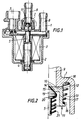
- the solenoid valve of Figures 1 and 2 comprises a body 1 and a cover 2 delimiting a space in which is housed an electromagnet coil 3. Inside the coil hub is disposed a fixed magnetic core 4 and a movable core 5 axially distant with a variable length defining the air gap of the coil. The smaller the air gap, the stronger the force of attraction of the moving core 5 by the fixed core 4 for a given power supply duty cycle of the coil.
- the coil 3 is supplied with chopped current with variable duty cycle from a connector 7 formed in the housing 1.
- the housing 1 also forms an inlet conduit 8 and an outlet conduit 9 for fluid for the space inside the housing.
- the inner end of the duct 9 delimits a first seat 10 with which an intermediate member 11 cooperates.
- This member 11 is in the form of a cup with a bottom 12 and a substantially cylindrical side wall 13.
- the face of the bottom 12 external to the cup is opposite the seat 10.
- the bottom 12 also comprises an orifice 14, the the part located on the inside of the cup is chamfered so as to form a second seat 15, conical, coaxial with the first seat, and the opening section of which is smaller than that of the first seat 10.
- a shoulder 16 of the wall 13 receives one end of a helical spring (here frustoconical) 17 whose other end is supported in a groove 18 formed in the housing 1.
- the spring 17 therefore pushes the member 10 to the seat deviation 10.
- the movable core 5 is formed of a cylindrical rod, one end of which is engaged in the hub of the coil, and the other end of which is cone-shaped 19 and is engaged inside the member 13 to cooperate with seat 15 of the latter.
- a shoulder 20 receives one end of another spring 21, the other end of which bears on the housing so as to tend to apply the conical end of the core 5 to the second seat 15.
- the solenoid valve which has just been described operates in the following manner.
- the seat 10 is therefore open, allowing a high flow rate. This regime is that of part A of the curve in FIG. 3 where the flow rate increases very rapidly with depression.
- FIG. 4 shows a fuel tank 30 for an internal combustion engine, and in particular for a motor vehicle engine.
- the reservoir 30 has a filling orifice 31 as well as another orifice from which a pipe 32 leaves, the other end of which is connected to a gasoline vapor trap 33 with activated carbon.
- the outlet of the trap 33 is connected to the inlet of a solenoid valve 34 of the type which has just been described. This solenoid valve 34 is controlled by a computer 35.
- the outlet of the solenoid valve 34 is connected to the inlet of a butterfly valve 36, to which the air and petrol also arrive, and the outlet of which is connected in a known manner to the injector supply ramp 37 of the motor.
- the computer 35 controls, as a function of the speed of rotation of the engine, the duty cycle of the chopped current supplying the coil 7 and thus controls the flow of gasoline vapors into the solenoid valve 34.
- This solenoid valve is closed at rest, i.e. when the engine is at rest. It opens gradually by increasing the duty cycle to the extent that the computer requests it.
- valve according to the invention the recycling of gasoline vapors is carried out suitably, including at high speed, when the engine vacuum is low, while keeping good accuracy on the flow rate at low speed.
Abstract
Description
La présente invention concerne un clapet d'électrovanne et un circuit de recyclage de vapeurs d'essence de moteur à combustion interne. Plus particulièrement, elle concerne un clapet d'électrovanne comportant un siège et une bobine d'électroaimant, ledit clapet comprenant l'extrémité libre d'un noyau mobile à l'intérieur du moyeu de ladite bobine.The present invention relates to a solenoid valve and a circuit for recycling petrol vapor from an internal combustion engine. More particularly, it relates to a solenoid valve comprising a seat and an electromagnet coil, said valve comprising the free end of a movable core inside the hub of said coil.
Dans les clapets de ce type, la bobine de l'électroaimant est généralement alimentée en courant haché de période constante et de rapport cyclique variable, le rapport cyclique étant défini comme le rapport de la durée pendant laquelle, au cours d'une période, la tension est à un niveau haut, à la durée de la période. L'extrémité libre du noyau mobile forme un clapet dont la position varie en fonction de la dépression en aval de l'électrovanne et du rapport cyclique d'ouverture, entre une position de fermeture où cette extrémité libre est en appui sur le siège et ferme par conséquent l'électrovanne, et une position le plus à l'écart du siège où le débit est maximum. Bien entendu, le débit est fonction à la fois de l'écartement entre le clapet et le siège ainsi que de la dépression régnant entre l'intérieur et l'extérieur de l'électrovanne.In valves of this type, the solenoid coil is generally supplied with chopped current of constant period and of variable duty cycle, the duty cycle being defined as the ratio of the duration during which, during a period, the tension is at a high level, for the duration of the period. The free end of the movable core forms a valve, the position of which varies according to the vacuum downstream of the solenoid valve and the opening duty cycle, between a closed position where this free end is supported on the seat and closes consequently the solenoid valve, and a position furthest from the seat where the flow is maximum. Of course, the flow rate is a function both of the spacing between the valve and the seat as well as of the vacuum prevailing between the interior and the exterior of the solenoid valve.
Un problème qui se pose est celui du débit pour de très faibles dépressions. En effet, dans les électrovannes connues, le débit à faible dépression est lui-même très faible, instable et non reproductible. Or il arrive que l'on souhaite de forts débits bien que la dépression soit faible.A problem which arises is that of the flow rate for very low depressions. Indeed, in known solenoid valves, the low vacuum flow is itself very low, unstable and non-reproducible. However it happens that one wishes for high flow rates although the depression is low.
Ceci est le cas en particulier dans les circuits de recyclage des vapeurs d'essence dans les moteurs à combustion interne. De tels circuits visent à recycler à l'entrée du moteur les vapeurs d'essence contenues dans le réservoir. La dépression est ici fournie par l'alimentation du moteur. Elle est donc faible à faible charge, de sorte que le recyclage est peu efficace.This is particularly the case in the gas vapor recycling circuits in internal combustion engines. Such circuits aim to recycle at the engine inlet the gasoline vapors contained in the tank. The vacuum is provided here by the motor supply. It is therefore low at low load, so that recycling is ineffective.
La présente invention vise à pallier ces inconvénients. Plus particulièrement, l'invention vise à fournir un clapet d'électrovanne qui possède un débit important pour de faibles différences de pression et qui, pour des différences de pression plus importantes, possède un débit plus faible et une caractéristique débit/pression d'électrovanne classique.The present invention aims to overcome these drawbacks. More particularly, the invention aims to provide a solenoid valve which has a large flow rate for small pressure differences and which, for larger pressure differences, has a lower flow rate and a typical solenoid valve flow / pressure characteristic.
A cet effet, l'invention a tout d'abord pour objet un clapet d'électrovanne comportant un siège et une bobine d'électroaimant, ledit clapet comprenant l'extrémité libre d'un noyau mobile à l'intérieur du moyeu de ladite bobine, caractérisé par le fait qu'il comprend en outre un organe intermédiaire susceptible de venir en appui sur ledit siège et comportant lui-même un deuxième siège, en vis-à-vis du premier siège et de section plus faible que celle du premier siège, ladite extrémité libre du noyau mobile étant susceptible de venir en appui sur ledit deuxième siège et des moyens élastiques étant prévus pour presser ledit organe intermédiaire à l'écart dudit premier siège.To this end, the invention firstly relates to a solenoid valve comprising a seat and an electromagnet coil, said valve comprising the free end of a movable core inside the hub of said coil , characterized by the fact that it further comprises an intermediate member capable of coming to bear on said seat and itself comprising a second seat, facing the first seat and of smaller cross section than that of the first seat , said free end of the movable core being capable of coming to bear on said second seat and elastic means being provided for pressing said intermediate member away from said first seat.
On verra ci-après qu'un tel agencement permet, tant que la dépression en aval du clapet est faible, l'ouverture du premier siège et donc un fort débit, puis, lorsque la dépression s'accroît, la fermeture du premier siège au profit du deuxième et donc un débit moins important et une caractéristique de fonctionnement classique.We will see below that such an arrangement allows, as long as the vacuum downstream of the valve is low, the opening of the first seat and therefore a high flow, then, when the vacuum increases, the closing of the first seat to advantage of the second and therefore a lower flow and a classic operating characteristic.
Dans un mode de réalisation particulier de l'invention, ledit organe intermédiaire est en forme de coupelle, ledit deuxième siège étant formé dans le fond de ladite coupelle, ledit fond étant, du côté de sa face extérieure, en vis-à-vis dudit premier siège, et ladite extrémité libre du noyau étant engagée à l'intérieur de ladite coupelle.In a particular embodiment of the invention, said intermediate member is in the form of a cup, said second seat being formed in the bottom of said cup, said bottom being, on the side of its outer face, facing said first seat, and said free end of the core being engaged inside said cup.
Egalement dans un mode de réalisation particulier, lesdits moyens élastiques comprennent un ressort hélicoïdal en appui, à une de ses extrémités sur une surface d'appui du boîtier, et à son autre extrémité sur un épaulement dudit organe intermédiaire.Also in a particular embodiment, said elastic means comprise a helical spring in abutment, at one of its ends on a bearing surface of the housing, and at its other end on a shoulder of said intermediate member.
Ladite extrémité libre du noyau mobile et ledit deuxième siège peuvent être coniques.Said free end of the movable core and said second seat can be conical.
Des deuxièmes moyens élastiques peuvent en outre être agencés pour presser ledit noyau mobile en direction dudit deuxième siège.Second elastic means can also be arranged to press said movable core towards said second seat.
La présente invention a également pour objet un circuit de recyclage de vapeurs d'essence de moteur à combustion interne, caractérisé par le fait qu'il comprend une électrovanne possédant un clapet tel que décrit ci-dessus.The present invention also relates to a circuit for recycling petrol vapor from an internal combustion engine, characterized in that it comprises a solenoid valve having a valve as described above.
On décrira maintenant, à titre d'exemple non limitatif, un mode de réalisation particulier de l'invention, en référence aux dessins schématiques annexés dans lesquels:
- la figure 1 est vue en coupe axiale d'une électrovanne comportant un clapet selon l'invention;
- la figure 2 est une demi-vue à plus grande échelle du détail l de la figure 1;
- la figure 3 illustre la caractéristique de fonctionnement de la vanne de la figure 1; et
- la figure 4 représente schématiquement un circuit de recyclage de vapeurs d'essence comportant le clapet de la figure 1.
- Figure 1 is an axial sectional view of a solenoid valve comprising a valve according to the invention;
- Figure 2 is a half-view on a larger scale of the detail l of Figure 1;
- Figure 3 illustrates the operating characteristic of the valve of Figure 1; and
- FIG. 4 schematically represents a circuit for recycling petrol vapors comprising the valve of FIG. 1.
L'électrovanne des figures 1 et 2 comporte un corps 1 et un couvercle 2 délimitant un espace dans lequel est logée une bobine d'électroaimant 3. A l'intérieur du moyeu de la bobine est disposé un noyau magnétique fixe 4 et un noyau mobile 5 distants axialement d'une longueur variable définissant l'entrefer de la bobine. Plus l'entrefer est faible, et plus est forte pour un rapport cyclique d'alimentation de la bobine donné, la force d'attraction du noyau mobile 5 par le noyau fixe 4.The solenoid valve of Figures 1 and 2 comprises a
La bobine 3 est alimentée en courant haché à rapport cyclique variable à partir d'un connecteur 7 formé dans le boîtier 1.The
Le boîtier 1 forme par ailleurs un conduit d'entrée 8 et un conduit de sortie 9 de fluide pour l'espace intérieur au boîtier. L'extrémité intérieure du conduit 9 délimite un premier siège 10 avec lequel coopère un organe intermédiaire 11.The
Cet organe 11 est en forme de coupelle avec un fond 12 et une paroi latérale sensiblement cylindrique 13. La face du fond 12 extérieure à la coupelle est en vis-à-vis du siège 10. Le fond 12 comporte en outre un orifice 14 dont la partie située du côté intérieur de la coupelle est chanfreinée de manière à former un deuxième siège 15, conique, coaxial au premier siège, et dont la section d'ouverture est plus petite que celle du premier siège 10.This
Un épaulement 16 de la paroi 13 reçoit une extrémité d'un ressort hélicoïdal (ici tronconique) 17 dont l'autre extrémité est en appui dans une gorge 18 formée dans le boîtier 1. Le ressort 17 repousse donc l'organe 10 à l'écart du siège 10.A
Le noyau mobile 5 est formé d'une tige cylindrique dont une extrémité est engagée dans le moyeu de la bobine, et dont l'autre extrémité est en forme de cône 19 et est engagée à l'intérieur de l'organe 13 pour coopérer avec le siège 15 de ce dernier. Un épaulement 20 reçoit une extrémité d'un autre ressort 21 dont l'autre extrémité est en appui sur le boîtier de manière à tendre à appliquer l'extrémité conique du noyau 5 sur le deuxième siège 15.The
L'électrovanne qui vient d'être décrite fonctionne de la manière suivante.The solenoid valve which has just been described operates in the following manner.
A l'arrêt, le clapet est fermé comme représenté aux dessins, la force exercée par le ressort 21 étant supérieure à celle du ressort 17.When stopped, the valve is closed as shown in the drawings, the force exerted by the
Lorsque la tige 5 est sollicitée par l'électroaimant et que la dépression est faible, le cône 19 tend à s'écarter du siège 15 en comprimant le ressort 21. Toutefois, du fait que la dépression est peu importante, le ressort 17 repousse l'organe 11 à l'écart du siège 10, le siège 15 demeurant fermé.When the
Le siège 10 est donc ouvert, permettant un fort débit. Ce régime est celui de la partie A de la courbe de la figure 3 où le débit augmente très rapidement avec la dépression.The
La dépression augmentant et atteignant la valeur P₀, l'organe 10 est "aspiré" vers le siège 10 et ferme ce siège tout en ouvrant le siège 15, de section plus faible. Le point de fonctionnement de la vanne se trouve donc déplacé sur la partie B de la courbe de la figure 3.As the vacuum increases and reaches the value P₀, the
La figure 4 montre un réservoir 30 d'essence pour moteur à combustion interne, et notamment pour moteur de véhicule automobile. Le réservoir 30 possède un orifice 31 de remplissage ainsi qu'un autre orifice d'où part une canalisation 32 dont l'autre extrémité est reliée à un piège à vapeurs d'essence 33 à charbon actif. La sortie du piège 33 est reliée à l'entrée d'une électrovanne 34 du type de celle qui vient d'être décrite. Cette électrovanne 34 est commandée par un calculateur 35.FIG. 4 shows a
La sortie de l'électrovanne 34 est reliée à l'entrée d'une vanne papillon 36, à laquelle arrivent par ailleurs l'air et l'essence et dont la sortie est reliée de façon connue à la rampe 37 d'alimentation des injecteurs du moteur.The outlet of the
Le calculateur 35 commande, en fonction de la vitesse de rotation du moteur, le rapport cyclique du courant haché alimentant la bobine 7 et commande ainsi le débit de vapeurs d'essence dans l'électrovanne 34. Cette électrovanne est fermée au repos, c'est-à-dire lorsque le moteur est au repos. Elle s'ouvre progressivement par augmentation du rapport cyclique dans la mesure où le calculateur en effectue la demande.The
Grâce au clapet selon l'invention, le recyclage des vapeurs d'essence est réalisé convenablement, y compris à fort régime, lorsque la dépression moteur est faible, tout en gardant une bonne précision sur le débit à faible régime.Thanks to the valve according to the invention, the recycling of gasoline vapors is carried out suitably, including at high speed, when the engine vacuum is low, while keeping good accuracy on the flow rate at low speed.
Claims (6)
Applications Claiming Priority (2)
| Application Number | Priority Date | Filing Date | Title |
|---|---|---|---|
| FR9413758A FR2727185A1 (en) | 1994-11-17 | 1994-11-17 | SOLENOID VALVE AND INTERNAL COMBUSTION ENGINE FUEL VAPOR RECYCLING CIRCUIT |
| FR9413758 | 1994-11-17 |
Publications (2)
| Publication Number | Publication Date |
|---|---|
| EP0713036A1 true EP0713036A1 (en) | 1996-05-22 |
| EP0713036B1 EP0713036B1 (en) | 2002-01-09 |
Family
ID=9468877
Family Applications (1)
| Application Number | Title | Priority Date | Filing Date |
|---|---|---|---|
| EP95402505A Expired - Lifetime EP0713036B1 (en) | 1994-11-17 | 1995-11-09 | Electromagnetic valve and recirculation circuit for fuel vapour of an internal combustion engine |
Country Status (5)
| Country | Link |
|---|---|
| US (1) | US5657962A (en) |
| EP (1) | EP0713036B1 (en) |
| JP (1) | JPH08210548A (en) |
| DE (1) | DE69524929T2 (en) |
| FR (1) | FR2727185A1 (en) |
Cited By (9)
| Publication number | Priority date | Publication date | Assignee | Title |
|---|---|---|---|---|
| DE10229789A1 (en) * | 2002-02-02 | 2003-08-14 | Continental Teves Ag & Co Ohg | Electromagnetic valve for operating as a 2-way seat valve, has a cartridge-shaped valve casing with a magnetic armature opposite a magnetic core and a valve-closing element on a valve needle. |
| WO2012098460A3 (en) * | 2011-01-21 | 2012-10-18 | Eaton Corporation | Isolation valve with fast depressurization for high-pressure fuel tank |
| ITBO20110563A1 (en) * | 2011-10-03 | 2013-04-04 | Magneti Marelli Spa | CANISTER VALVE WITH REDUCED ACTUATION FORCE |
| US8944101B2 (en) | 2009-04-22 | 2015-02-03 | Eaton Corporation | Valve assembly for high-pressure fluid reservoir |
| USD747784S1 (en) | 2010-03-30 | 2016-01-19 | Eaton Corporation | Fuel tank isolation valve |
| USD750746S1 (en) | 2010-03-30 | 2016-03-01 | Eaton Corporation | Fuel tank isolation valve |
| US9371803B2 (en) | 2009-04-22 | 2016-06-21 | Eaton Corporation | Valve assembly |
| US9500291B2 (en) | 2010-03-30 | 2016-11-22 | Eaton Corporation | Isolation valve with fast depressurization for high-pressure fuel tank |
| USD829304S1 (en) | 2010-03-30 | 2018-09-25 | Eaton Intelligent Power Limited | Valve carriage |
Families Citing this family (19)
| Publication number | Priority date | Publication date | Assignee | Title |
|---|---|---|---|---|
| DE19529724A1 (en) * | 1995-08-12 | 1997-02-13 | Teves Gmbh Alfred | Solenoid valve, in particular for hydraulic motor vehicle brake systems with wheel slip control |
| US6050245A (en) * | 1997-02-12 | 2000-04-18 | Siemens Canada Limited | Canister vent valve having at least one sensor and single electric actuator operatively connected to a single electrical connector |
| US5970958A (en) * | 1997-10-10 | 1999-10-26 | Eaton Corporation | Fuel vapor purge control |
| DE19836493B4 (en) * | 1998-03-31 | 2008-07-24 | Continental Teves Ag & Co. Ohg | Solenoid valve |
| US6309541B1 (en) | 1999-10-29 | 2001-10-30 | Ontogen Corporation | Apparatus and method for multiple channel high throughput purification |
| BR0011439B1 (en) * | 1999-06-08 | 2009-05-05 | purification solenoid valve for vapor evacuation device. | |
| US6394073B1 (en) | 1999-08-26 | 2002-05-28 | Caterpillar Inc. | Hydraulic valve with hydraulically assisted opening and fuel injector using same |
| US6358414B1 (en) | 1999-10-29 | 2002-03-19 | Ontogen Corporation | Pressure regulation apparatus and method for multiple channel high throughput purification |
| US6843271B2 (en) * | 2000-08-08 | 2005-01-18 | Siemens Vdo Automotive, Inc. | Fuel tank pressure control valve including an integrated sensor |
| US6668807B2 (en) * | 2000-08-08 | 2003-12-30 | Siemens Automotive Inc. | Evaporative emission control system including a fuel tank isolation valve |
| CA2423179A1 (en) * | 2000-09-21 | 2002-03-28 | Digital Network Shopping, Llc | Method and apparatus for digital shopping |
| JP2002181221A (en) * | 2000-12-11 | 2002-06-26 | Smc Corp | Flow control valve |
| US6745794B2 (en) * | 2002-06-07 | 2004-06-08 | Praxair Technology, Inc. | Flow control valve |
| KR100721377B1 (en) * | 2003-02-07 | 2007-05-23 | 주식회사 만도 | Solenoid valve for brake system |
| US9316130B1 (en) | 2007-03-07 | 2016-04-19 | Thermal Power Recovery Llc | High efficiency steam engine, steam expander and improved valves therefor |
| US8448440B2 (en) * | 2007-03-07 | 2013-05-28 | Thermal Power Recovery Llc | Method and apparatus for achieving higher thermal efficiency in a steam engine or steam expander |
| JP6253623B2 (en) * | 2015-09-14 | 2017-12-27 | 本田技研工業株式会社 | Fuel shut-off valve |
| DE102017122253A1 (en) * | 2017-09-26 | 2019-03-28 | Eagle Actuator Components Gmbh & Co. Kg | Active and passive actuated valve |
| CN113280519B (en) * | 2021-05-27 | 2022-12-23 | 深圳嘉普通太阳能股份有限公司 | Domestic solar water heater |
Citations (4)
| Publication number | Priority date | Publication date | Assignee | Title |
|---|---|---|---|---|
| EP0005395A1 (en) * | 1978-05-08 | 1979-11-14 | SAUNIER DUVAL EAU CHAUDE CHAUFFAGE S.D.E.C.C. - Société anonyme | Device for regulating the reduced flow of an electromagnetic valve of an apparatus of the gas-operated boiler type |
| FR2437554A1 (en) * | 1978-09-26 | 1980-04-25 | Saunier Duval | Solenoid valve for control of gas supply - has lever to adjust spring force to suit local gas supply pressure |
| US4944276A (en) * | 1987-10-06 | 1990-07-31 | Colt Industries Inc | Purge valve for on board fuel vapor recovery systems |
| WO1992008918A1 (en) * | 1990-11-19 | 1992-05-29 | Tour & Andersson Ab | A valve for a two-way or multiple-way flow regulation |
Family Cites Families (12)
| Publication number | Priority date | Publication date | Assignee | Title |
|---|---|---|---|---|
| US2866477A (en) * | 1954-03-19 | 1958-12-30 | Crane Co | Combined throttle and stop valve |
| US2983286A (en) * | 1959-01-19 | 1961-05-09 | Ranco Inc | Reversing valve |
| JPS579380A (en) * | 1980-06-20 | 1982-01-18 | Hitachi Ltd | Proportional control valve |
| JPS5770727A (en) * | 1980-10-22 | 1982-05-01 | Hitachi Ltd | Pressure control valve unit |
| FR2598992B1 (en) * | 1986-05-26 | 1992-04-03 | Jidosha Kiki Co | VEHICLE SERVO BRAKE |
| GB8727297D0 (en) * | 1987-11-20 | 1987-12-23 | Lucas Ind Plc | Solenoid valve |
| JPH01174683U (en) * | 1988-05-31 | 1989-12-12 | ||
| US5174262A (en) * | 1989-04-14 | 1992-12-29 | Brunswick Corporation | Control valve for fuel injection |
| JPH0560259A (en) * | 1991-08-28 | 1993-03-09 | Mitsubishi Electric Corp | Flow rate control valve |
| DE4229105C1 (en) * | 1992-09-01 | 1993-09-09 | Fa. Carl Freudenberg, 69469 Weinheim, De | |
| DE4329396A1 (en) * | 1993-09-01 | 1995-03-02 | Pierburg Gmbh | Electropneumatic control valve |
| US5509395A (en) * | 1995-03-31 | 1996-04-23 | Siemens Electric Limited | Canister purge flow regulator |
-
1994
- 1994-11-17 FR FR9413758A patent/FR2727185A1/en active Granted
-
1995
- 1995-11-09 EP EP95402505A patent/EP0713036B1/en not_active Expired - Lifetime
- 1995-11-09 DE DE69524929T patent/DE69524929T2/en not_active Expired - Fee Related
- 1995-11-17 US US08/559,909 patent/US5657962A/en not_active Expired - Fee Related
- 1995-11-17 JP JP7299619A patent/JPH08210548A/en active Pending
Patent Citations (4)
| Publication number | Priority date | Publication date | Assignee | Title |
|---|---|---|---|---|
| EP0005395A1 (en) * | 1978-05-08 | 1979-11-14 | SAUNIER DUVAL EAU CHAUDE CHAUFFAGE S.D.E.C.C. - Société anonyme | Device for regulating the reduced flow of an electromagnetic valve of an apparatus of the gas-operated boiler type |
| FR2437554A1 (en) * | 1978-09-26 | 1980-04-25 | Saunier Duval | Solenoid valve for control of gas supply - has lever to adjust spring force to suit local gas supply pressure |
| US4944276A (en) * | 1987-10-06 | 1990-07-31 | Colt Industries Inc | Purge valve for on board fuel vapor recovery systems |
| WO1992008918A1 (en) * | 1990-11-19 | 1992-05-29 | Tour & Andersson Ab | A valve for a two-way or multiple-way flow regulation |
Cited By (13)
| Publication number | Priority date | Publication date | Assignee | Title |
|---|---|---|---|---|
| DE10229789A1 (en) * | 2002-02-02 | 2003-08-14 | Continental Teves Ag & Co Ohg | Electromagnetic valve for operating as a 2-way seat valve, has a cartridge-shaped valve casing with a magnetic armature opposite a magnetic core and a valve-closing element on a valve needle. |
| US8944101B2 (en) | 2009-04-22 | 2015-02-03 | Eaton Corporation | Valve assembly for high-pressure fluid reservoir |
| US9371803B2 (en) | 2009-04-22 | 2016-06-21 | Eaton Corporation | Valve assembly |
| USD750746S1 (en) | 2010-03-30 | 2016-03-01 | Eaton Corporation | Fuel tank isolation valve |
| US8944100B2 (en) | 2010-03-30 | 2015-02-03 | Eaton Corporation | Isolation valve with fast depressurization for high-pressure fuel tank |
| USD747784S1 (en) | 2010-03-30 | 2016-01-19 | Eaton Corporation | Fuel tank isolation valve |
| US9500291B2 (en) | 2010-03-30 | 2016-11-22 | Eaton Corporation | Isolation valve with fast depressurization for high-pressure fuel tank |
| USD829304S1 (en) | 2010-03-30 | 2018-09-25 | Eaton Intelligent Power Limited | Valve carriage |
| CN103328805A (en) * | 2011-01-21 | 2013-09-25 | 伊顿公司 | Isolation valve with fast depressurization for high-pressure fuel tank |
| CN103328805B (en) * | 2011-01-21 | 2016-01-13 | 伊顿公司 | For the separating valve of the fast decompression of high-pressure propellant tank |
| WO2012098460A3 (en) * | 2011-01-21 | 2012-10-18 | Eaton Corporation | Isolation valve with fast depressurization for high-pressure fuel tank |
| EP2581596A1 (en) * | 2011-10-03 | 2013-04-17 | Magneti Marelli S.p.A. | Low actuating force canister purge valve |
| ITBO20110563A1 (en) * | 2011-10-03 | 2013-04-04 | Magneti Marelli Spa | CANISTER VALVE WITH REDUCED ACTUATION FORCE |
Also Published As
| Publication number | Publication date |
|---|---|
| FR2727185A1 (en) | 1996-05-24 |
| FR2727185B1 (en) | 1997-02-14 |
| DE69524929D1 (en) | 2002-02-14 |
| DE69524929T2 (en) | 2002-08-22 |
| EP0713036B1 (en) | 2002-01-09 |
| US5657962A (en) | 1997-08-19 |
| JPH08210548A (en) | 1996-08-20 |
Similar Documents
| Publication | Publication Date | Title |
|---|---|---|
| EP0713036B1 (en) | Electromagnetic valve and recirculation circuit for fuel vapour of an internal combustion engine | |
| EP0119894B1 (en) | Electromagnetically driven pressure time-dependent injection system for diesel engines, the valve needle being driven by discharging and charging a capacity | |
| EP1040266B1 (en) | Control valve for recirculation system of an internal combustion engine exhaust gases | |
| FR2716936A1 (en) | Fuel distribution circuit for an internal combustion engine. | |
| FR2738294A1 (en) | INJECTOR FOR INTERNAL COMBUSTION ENGINE | |
| FR2463294A1 (en) | PRECISION ELECTRO-INJECTION FOR INTERNAL COMBUSTION ENGINES | |
| FR2528913A1 (en) | FUEL INJECTOR | |
| EP0631075A1 (en) | Electro-magnetic double seat valve, and recirculation circuit for petrol vapor | |
| EP0631076B1 (en) | Electromagnetic valve with tubular metallic core | |
| FR2832457A1 (en) | FUEL METERING DEVICE FOR A TURBOMACHINE INJECTOR | |
| EP0006770B1 (en) | Electromagnetic valve, especially for a carburetor | |
| FR2727158A1 (en) | Control valve for selective recycling of IC engine exhaust gas | |
| FR2792371A1 (en) | CONTROL VALVE FOR AN INJECTION DEVICE COMPRISING A PISTON AND STOPPERS THEREFOR | |
| EP1525385B1 (en) | Gaseous fuel injector | |
| FR2797914A1 (en) | FUEL INJECTOR CONTROL VALVE | |
| EP0914557B1 (en) | Solenoid valve such as an impact solenoid valve for a hammer-effect fuel injection system in a motor vehicle | |
| EP0456535A1 (en) | Intake device for a mixture inducing internal combustion engine | |
| FR2790301A1 (en) | VARIABLE PASSAGE SECTION VALVE | |
| FR2778784A1 (en) | Electro-valve for control of purging component of fuel system in IC engine | |
| EP0072269B1 (en) | Fuel injector, especially for an internal-combustion engine | |
| FR2511083A1 (en) | Actuator for carburettor fuel pump - has lever actuated by butterfly valve cable with cam surface to control pump push rod | |
| EP4088017A1 (en) | Electromagnetic actuator | |
| FR2714114A1 (en) | I.C. engine air feed throttle | |
| WO2019101499A1 (en) | Fuel injector | |
| FR2934649A1 (en) | Fuel injecting device for internal combustion engine i.e. diesel engine, has control piston for closing control chamber supplied with high pressure fuel by inlet nozzle, where inlet nozzle presents variable fuel passage section |
Legal Events
| Date | Code | Title | Description |
|---|---|---|---|
| PUAI | Public reference made under article 153(3) epc to a published international application that has entered the european phase |
Free format text: ORIGINAL CODE: 0009012 |
|
| AK | Designated contracting states |
Kind code of ref document: A1 Designated state(s): DE GB IT |
|
| 17P | Request for examination filed |
Effective date: 19961025 |
|
| 17Q | First examination report despatched |
Effective date: 19990708 |
|
| GRAG | Despatch of communication of intention to grant |
Free format text: ORIGINAL CODE: EPIDOS AGRA |
|
| GRAG | Despatch of communication of intention to grant |
Free format text: ORIGINAL CODE: EPIDOS AGRA |
|
| GRAH | Despatch of communication of intention to grant a patent |
Free format text: ORIGINAL CODE: EPIDOS IGRA |
|
| GRAH | Despatch of communication of intention to grant a patent |
Free format text: ORIGINAL CODE: EPIDOS IGRA |
|
| GRAA | (expected) grant |
Free format text: ORIGINAL CODE: 0009210 |
|
| REG | Reference to a national code |
Ref country code: GB Ref legal event code: IF02 |
|
| AK | Designated contracting states |
Kind code of ref document: B1 Designated state(s): DE GB IT |
|
| PG25 | Lapsed in a contracting state [announced via postgrant information from national office to epo] |
Ref country code: IT Free format text: LAPSE BECAUSE OF FAILURE TO SUBMIT A TRANSLATION OF THE DESCRIPTION OR TO PAY THE FEE WITHIN THE PRE;WARNING: LAPSES OF ITALIAN PATENTS WITH EFFECTIVE DATE BEFORE 2007 MAY HAVE OCCURRED AT ANY TIME BEFORE 2007. THE CORRECT EFFECTIVE DATE MAY BE DIFFERENT FROM THE ONE RECORDED.SCRIBED TIME-LIMIT Effective date: 20020109 |
|
| REF | Corresponds to: |
Ref document number: 69524929 Country of ref document: DE Date of ref document: 20020214 |
|
| GBT | Gb: translation of ep patent filed (gb section 77(6)(a)/1977) |
Effective date: 20020417 |
|
| PG25 | Lapsed in a contracting state [announced via postgrant information from national office to epo] |
Ref country code: GB Free format text: LAPSE BECAUSE OF NON-PAYMENT OF DUE FEES Effective date: 20021109 |
|
| PLBE | No opposition filed within time limit |
Free format text: ORIGINAL CODE: 0009261 |
|
| STAA | Information on the status of an ep patent application or granted ep patent |
Free format text: STATUS: NO OPPOSITION FILED WITHIN TIME LIMIT |
|
| 26N | No opposition filed | ||
| PG25 | Lapsed in a contracting state [announced via postgrant information from national office to epo] |
Ref country code: DE Free format text: LAPSE BECAUSE OF NON-PAYMENT OF DUE FEES Effective date: 20030603 |
|
| GBPC | Gb: european patent ceased through non-payment of renewal fee |